CN211594590U - Wire arranging mechanism suitable for zipper tape winder - Google Patents
Wire arranging mechanism suitable for zipper tape winder Download PDFInfo
- Publication number
- CN211594590U CN211594590U CN201922283762.8U CN201922283762U CN211594590U CN 211594590 U CN211594590 U CN 211594590U CN 201922283762 U CN201922283762 U CN 201922283762U CN 211594590 U CN211594590 U CN 211594590U
- Authority
- CN
- China
- Prior art keywords
- winding
- winding displacement
- unwinding
- guide rail
- base
- Prior art date
- Legal status (The legal status is an assumption and is not a legal conclusion. Google has not performed a legal analysis and makes no representation as to the accuracy of the status listed.)
- Expired - Fee Related
Links
Images


Abstract
The utility model discloses a winding displacement mechanism suitable for zip fastener taping machine, including winding displacement mechanism, winding displacement mechanism includes traction plate, winding displacement base, winding displacement guide rail, winding displacement drive assembly, closes on left switching-over proximity switch and the right switching-over proximity switch who locates the winding displacement guide rail both ends respectively, wherein, the winding displacement guide rail is on a parallel with the axial length direction of wind-up roll, the winding displacement base is connected to on the winding displacement guide rail in a sliding manner and the winding displacement drive assembly is used for driving the winding displacement base to slide along the reciprocating of winding displacement guide rail, the traction plate upper end articulates on the winding displacement base; when any one of the left reversing proximity switch and the right reversing proximity switch senses that the flat cable base is in place, the flat cable driving component is fed back and controlled to conduct reversing driving.
Description
Technical Field
The utility model belongs to the technical field of the technique of zip fastener processing equipment and specifically relates to indicate a winding displacement mechanism suitable for zip fastener rolling machine.
Background
The existing zipper tape winder generally uses a polished rod wire arranging device, and has the advantages that stepless speed regulation can be realized by adjusting a mechanical operating rod on the wire arranging device, and the requirement of accurately adjusting the wire arranging pitch is met. The reversing is realized by the fact that the reversing arm collides with the reversing block, and the reversing is rapid. However, since the polished rod traverse is a mechanical structure, it is difficult to match the polished rod traverse to achieve programmed control, because the operating rod needs to be manually adjusted when the program is changed.
The pitch of the flat cable needs to be adjusted in a flat cable stroke in part of processes, although the flat cable arranging device can be used by adjusting the rotating speed of the polished rod, the rotating speed needs to be calculated and input into the scales of the operating rod on the flat cable arranging device, and meanwhile, a motor needs to be independently configured for the polished rod flat cable arranging device, and a common polished rod flat cable arranging device mechanism and a zipper tube share one motor, so that the process is complicated.
SUMMERY OF THE UTILITY MODEL
An object of the utility model is to overcome the not enough of prior art, provide a winding displacement mechanism suitable for zip fastener taping machine.
In order to achieve the purpose, the utility model provides a winding displacement mechanism suitable for zip fastener tape winder, including the winding displacement mechanism, the winding displacement mechanism includes traction plate, winding displacement base, winding displacement guide rail, winding displacement drive assembly, closes on respectively and locates left switching-over proximity switch and the right switching-over proximity switch at winding displacement guide rail both ends, wherein, the winding displacement guide rail is on a parallel with the axial length direction of wind-up roll, the winding displacement base sliding connection is to the winding displacement guide rail and the winding displacement drive assembly is used for driving the winding displacement base to slide along the reciprocating of winding displacement guide rail, the winding displacement base of traction plate upper end articulates on the base; when any one of the left reversing proximity switch and the right reversing proximity switch senses that the flat cable base is in place, the flat cable driving component is fed back and controlled to conduct reversing driving.
Furthermore, the winding displacement drive assembly comprises two synchronizing wheels, a synchronous belt wound on the two synchronizing wheels and a servo motor, wherein the servo motor is in transmission connection with one of the synchronizing wheels, and the synchronous belt is connected with the winding displacement base.
The utility model adopts the above technical scheme, its beneficial effect lies in: the winding displacement mechanism is provided with a winding displacement mechanism, a winding displacement mechanism is arranged on the winding displacement mechanism, the winding displacement mechanism is arranged on the winding displacement mechanism, and the winding displacement mechanism is provided with a left reversing proximity switch and a right reversing proximity switch.
Drawings
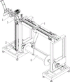
Fig. 1 is a schematic structural diagram of the tape winding machine according to the embodiment.
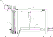
Fig. 2 is a front view of the tape winder of the present embodiment.
Fig. 3 is a schematic view of the feeding transmission mechanism of the embodiment.
Fig. 4 is a schematic view of the tension feedback mechanism of the present embodiment.
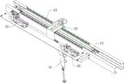
Fig. 5 is a schematic view of the wire arranging mechanism of the present embodiment.
The automatic winding machine comprises a feeding transmission mechanism 1, a feeding roller 11, a pinch roller 12, a feeding driving unit 13, a feeding guide roller 14, a tension feedback mechanism 2, a linear guide rail 21, a feedback roller 22, a transmission chain 23, a main wheel chain wheel 24, a main wheel chain wheel 25, an idler chain wheel 26, a buffer 26, a speed measuring wheel 3, a winding displacement mechanism 4, a traction plate 41, a winding displacement base 42, a winding displacement guide rail 43, a winding displacement driving assembly 44, a left reversing proximity switch 45, a right reversing proximity switch 46 and a winding roller 5.
Detailed Description
In order to facilitate understanding of the present invention, the present invention will be described more fully with reference to the accompanying drawings. The preferred embodiments of the present invention are shown in the drawings. The invention may, however, be embodied in many different forms and should not be construed as limited to the embodiments set forth herein. These embodiments are provided so that this disclosure will be thorough and complete.
Referring to fig. 1 to 5, in this embodiment, a zipper tape winding machine includes a feeding transmission mechanism 1, a tension feedback mechanism 15, a velocity measuring wheel 3, a winding mechanism 4, and a winding roller 5 in sequence along a zipper conveying direction. The feeding transmission mechanism 1 comprises a feeding roller 11, a pinch roller 12, two feeding guide rollers 14 and a feeding driving unit 13 for driving the feeding roller 11 to rotate, wherein the roller surface of the pinch roller 12 abuts against the feeding roller 11 to be conveyed and moved forward by a common pinch zipper of the two rollers; the two feeding guide rollers 14 are arranged at the upstream of the feeding roller 11, so that the zipper sequentially penetrates through the roller surfaces of the two feeding guide rollers 14 and the roller surface of the feeding roller 11, and then the feeding roller 11 and the pinch roller 12 pinch the zipper, thereby providing traction force for conveying the zipper.
In this embodiment, the diameter width of the velocity measuring wheel 3 is the same as the diameter width of the feeding roller 11, wherein the velocity measuring wheel 3 detects the conveying speed of the zipper in real time in the winding process, that is, the velocity measuring wheel 3 of this embodiment is configured with a first velocity measuring unit for detecting and feeding back the angular velocity thereof, and the zipper is wound through the roller surface of the velocity measuring wheel 3 to correspondingly drive the velocity measuring wheel 3 to rotate, so that the conveying linear velocity of the zipper is indirectly calculated by using the angular velocity detected by the first velocity measuring unit.
In this embodiment, the tension feedback mechanism 15 includes a linear guide rail 21 extending vertically and a feedback roller 22 slidably disposed on the linear guide rail 21, wherein a slider slidably connected to the linear guide rail 21 is disposed on the feedback roller 22, and the feedback roller 22 is hinged to the slider. In addition, the weight of the feedback roller 22 of the embodiment is equal to the rated winding tension value, so that the zipper is threaded through the feedback roller 22, the tension of the zipper is equivalent to the acting force exerted on the feedback roller 22, and the acting force and the gravity of the feedback roller 22 are used as balance force; therefore, when the tension of the zipper becomes higher than the rated winding tension value (corresponding to the gravity of the feedback roller 22), the feedback roller 22 is forced upward, and the feedback roller 22 moves upward along the linear guide 21; on the contrary, if the tension of the zipper becomes lower than the rated winding tension value (equivalent to the gravity of the feedback roller 22), the feedback roller 22 is subjected to a downward acting force, so that the feedback roller 22 moves downward along the linear guide 21, and thus the feedback roller 22 autonomously slides along the linear guide 21 along with the change of the winding tension of the zipper in the winding process.
Further, in order to realize real-time feedback of the winding tension, the tension feedback mechanism 15 of the embodiment further includes a transmission chain 23, a driving sprocket and an idle sprocket 25 which are in transmission fit with each other, that is, the transmission chain 23 circularly passes through the driving sprocket and the idle sprocket 25. The transmission chain 23 is connected with the slide block of the feedback roller 22, and the synchronous transmission chain 23 is driven to run along with the sliding action of the feedback roller 22, and the transmission chain 23 drives the driving sprocket and the idle sprocket 25 to rotate. In addition, the driving chain wheel is correspondingly connected with a second speed measuring unit for monitoring and feeding back the rotating speed of the driving chain wheel in real time.
In the embodiment, the take-up roll 5 and the feed roll 11 both provide traction for the zipper, wherein the take-up roll 5 rotates according to a preset program without participating in the adjustment of the zipper tension, that is, the zipper tension is changed by adjusting the linear speed difference between the take-up roll 5 and the feed roll 11. Therefore, the rotating speed of the feeding roller 11 is correspondingly adjusted according to the speed electric signal fed back by the second speed measuring unit of the driving sprocket, wherein when the second speed measuring unit detects the forward rotation of the driving sprocket (the feedback roller 22 is defined as moving upwards), the rotating speed of the feeding roller 11 is accelerated by controlling the feeding driving unit 13, so that the speed difference is reduced, and the effect of reducing the tension is achieved; on the contrary, when the second speed measuring unit detects the reverse rotation of the driving sprocket (the feedback roller 22 is defined as moving downwards), the rotating speed of the feeding roller 11 is increased by controlling the feeding driving unit 13, the speed difference is increased, and the effect of increasing the tension is achieved. The first speed measuring unit and the second speed measuring unit of this embodiment may employ a speed detecting sensor, for example, the hall sensor mentioned in reference CN203275433U is used in combination with a magnet emitting a magnetic signal as a common detecting method, and the structure and principle of the sensor belong to conventional technical means in the field, and are not described herein again.
In the present embodiment, the driving sprocket and the idle sprocket 25 are disposed up and down and disposed adjacent to both ends of the linear guide 21, respectively. In addition, the zipper tension monitoring device further comprises a protection proximity switch which is arranged at the position close to the main wheel chain wheel 24 and the idler chain and used for detecting the situation that the judging and feedback roller 22 is in the position, wherein when the feedback roller 22 moves upwards to trigger the protection proximity switch at the upper end position, the zipper tension at the moment is suddenly changed to exceed a rated maximum threshold value, namely: the condition of zipper knotting occurs in the rolling process; conversely, when the feedback roller 22 moves down and starts the protection proximity switch located at the lower end position, it indicates that the tension of the zipper at this time suddenly drops below the rated minimum threshold, that is, the zipper is completely wound. In both cases, the zipper tension is abnormal, and the machine needs to be stopped and braked immediately and manually disposed.
Further, both ends of the linear guide 21 are provided with buffers 26 for the feedback roller 22 to be in contact engagement with each other, and the buffers 26 exert a buffering effect on the feedback roller 22.
In the present embodiment, the winding displacement driving assembly 44 includes a pulling plate 41, a winding displacement base 42, a winding displacement guide rail 43 and the winding displacement driving assembly 44, wherein the winding displacement guide rail 43 is parallel to the axial direction of the winding roller 5 (the winding displacement guide rail 43 of the present embodiment is located above the winding roller 5). The bottom of the flat cable base 42 is slidably connected to the flat cable guide rail 43, and the flat cable driving assembly 44 is used for driving the flat cable base 42 to slide along the flat cable guide rail 43 in a reciprocating manner, wherein the flat cable driving assembly 44 comprises two synchronizing wheels, a synchronous belt wound on the two synchronizing wheels, and a flat cable driving motor, wherein the flat cable driving motor is in transmission connection with one of the synchronizing wheels, so that the synchronizing wheel serves as a driving wheel to drive the synchronous belt to run, the bottom end of the flat cable base 42 is connected with the synchronous belt through a preset belt clamp, and the synchronous belt drives the flat cable base 42 to slide in a reciprocating manner. The flat cable driving motor of the present embodiment is a servo motor.
Further, the pulling plate 41 is fixedly mounted on the flat cable base 42 through a bolt, wherein the upper end of the pulling plate 41 of the present embodiment is hinged to the flat cable base 42, that is, the upper end of the pulling plate 41 is hinged to the flat cable base 42 through a predetermined bearing seat and a rotating shaft, so that the pulling plate 41 can swing around the rotating shaft. Two limiting plates are formed at the lower end part of the traction plate 41, wherein the two limiting plates and the traction plate 41 form a U-shaped structure for the zipper to pass through, and the distance between the two limiting plates is slightly larger than the width of the zipper. With the reciprocating sliding action of the flat cable base 42, the pulling plate 41 can synchronously slide back and forth, so as to realize the function of winding the flat cable on the zipper.
Further, a flat cable guide wheel is provided on the flat cable base 42 so that the slide fastener conveyed from the velocity measuring wheel 3 is guided and pulled to the lower end of the traction plate 41 by the flat cable guide wheel.
In this embodiment, the traverse mechanism 4 further includes a left reversing proximity switch 45 and a right reversing proximity switch 46 respectively disposed adjacent to two ends of the traverse guide rail 43, wherein the positions of the left reversing proximity switch 45 and the right reversing proximity switch 46 respectively correspond to two ends of the wind-up roll 5; when any one of the left and right reversing proximity switches 45 and 46 senses that the flat cable base 42 is in place, the feedback controls the flat cable driving assembly 44 to perform the reversing driving. In this way, the traverse base 42 is held on the traverse guide 43 between the left and right direction changing proximity switches 45 and 46 to perform the reciprocating movement, thereby causing the pulling plate 41 to pull the zipper winding roller 5 to perform the winding operation.
The wind-up roll 5 of this embodiment is directly or indirectly driven by the driving motor to rotate and wind up.
In order to facilitate the understanding of the bag rolling machine, the working principle thereof is further explained below.
As shown in fig. 5, in this embodiment, two protection proximity switches are respectively connected to input ports of a preset PLC by using the PLC as a processor of the whole control system; the first speed measuring unit and the second speed measuring unit are respectively connected with an input port of a preset PLC, and the left reversing proximity switch 45 and the right reversing proximity switch 46 are respectively connected with an input port of the preset PLC; the feeding driving unit 13 is connected to an output port of the PLC; the winding displacement driving motor is connected to an output port of the PLC, and the driving motor of the winding roller 5 is connected to an output port of the PLC. According to a preset calculation program, the speed electric signal detected by the first speed measurement unit is transmitted to the PLC for processing, and can be visually displayed in a mode of externally connecting a display; the speed electrical signal detected by the second speed measuring unit is transmitted to the PLC to correspondingly control the rotating speed of the feeding driving unit 13. When any one of the two protective proximity switches detects that the generated in-place electric signal is transmitted to the PLC, the driving motor and the feeding driving unit 13 of the winding roller 5 are correspondingly controlled to stop running immediately. The electrical signal generated by the detection of the left or right reversing proximity switch 45 or 46 is transmitted to the PLC, and the flat cable driving motor is correspondingly controlled to perform the reversing operation, thereby realizing the reciprocating movement of the flat cable base 42. As a prior art, the PLC controller disclosed in chinese patent No. CN202258551U may be specifically referred to, and therefore, the principle of the PLC controller is not described in detail in this application.
Further, the feeding driving unit 13 and the flat cable driving motor of the present embodiment are variable speed servo motors.
The above-described embodiments are merely preferred embodiments of the present invention, which are not intended to limit the present invention in any way. Those skilled in the art can make many changes, modifications, and equivalents of the embodiments of the invention without departing from the scope of the invention. Therefore, the content of the technical scheme of the utility model, according to the equivalent change made by the idea of the utility model, should be covered in the protection scope of the utility model.
Claims (2)
1. The utility model provides a winding displacement mechanism suitable for zip fastener taping machine which characterized in that: the winding and unwinding device comprises a winding and unwinding mechanism (4), wherein the winding and unwinding mechanism (4) comprises a traction plate (41), a winding and unwinding base (42), a winding and unwinding guide rail (43), a winding and unwinding driving assembly (44), a left reversing proximity switch (45) and a right reversing proximity switch (46) which are respectively arranged at two ends of the winding and unwinding guide rail (43) in a close manner, the winding and unwinding guide rail (43) is parallel to the axial length direction of a winding roller (5), the winding and unwinding base (42) is connected onto the winding and unwinding guide rail (43) in a sliding manner, the winding and unwinding driving assembly (44) is used for driving the winding and unwinding base (42) to slide along the winding and unwinding guide rail (43) in a reciprocating manner, and the upper end of; when any one of the left reversing proximity switch (45) and the right reversing proximity switch (46) senses that the flat cable base (42) is in place, the flat cable driving component (44) is controlled in a feedback mode to conduct reversing driving.
2. The cable arranging mechanism for the zipper tape winding machine according to claim 1, wherein: the flat cable driving assembly (44) comprises two synchronizing wheels, a synchronous belt wound on the two synchronizing wheels and a servo motor, wherein the servo motor is in transmission connection with one of the synchronizing wheels, and the synchronous belt is connected with a flat cable base (42).
Priority Applications (1)
| Application Number | Priority Date | Filing Date | Title |
|---|---|---|---|
| CN201922283762.8U CN211594590U (en) | 2019-12-18 | 2019-12-18 | Wire arranging mechanism suitable for zipper tape winder |
Applications Claiming Priority (1)
| Application Number | Priority Date | Filing Date | Title |
|---|---|---|---|
| CN201922283762.8U CN211594590U (en) | 2019-12-18 | 2019-12-18 | Wire arranging mechanism suitable for zipper tape winder |
Publications (1)
| Publication Number | Publication Date |
|---|---|
| CN211594590U true CN211594590U (en) | 2020-09-29 |
Family
ID=72593346
Family Applications (1)
| Application Number | Title | Priority Date | Filing Date |
|---|---|---|---|
| CN201922283762.8U Expired - Fee Related CN211594590U (en) | 2019-12-18 | 2019-12-18 | Wire arranging mechanism suitable for zipper tape winder |
Country Status (1)
| Country | Link |
|---|---|
| CN (1) | CN211594590U (en) |
Cited By (1)
| Publication number | Priority date | Publication date | Assignee | Title |
|---|---|---|---|---|
| CN114275626A (en) * | 2021-12-31 | 2022-04-05 | 广东巴斯特科技股份有限公司 | Wire arranging method and wire arranging system for winding machine |
-
2019
- 2019-12-18 CN CN201922283762.8U patent/CN211594590U/en not_active Expired - Fee Related
Cited By (2)
| Publication number | Priority date | Publication date | Assignee | Title |
|---|---|---|---|---|
| CN114275626A (en) * | 2021-12-31 | 2022-04-05 | 广东巴斯特科技股份有限公司 | Wire arranging method and wire arranging system for winding machine |
| CN114275626B (en) * | 2021-12-31 | 2023-12-12 | 广东巴斯特科技股份有限公司 | Winding method and winding system for winding machine |
Similar Documents
| Publication | Publication Date | Title |
|---|---|---|
| CN202508684U (en) | Small-scale metal narrow-band wire coiling machine | |
| CN108861850B (en) | Automatic flat wire winding machine | |
| CN102556757A (en) | Small metal narrowband coiling machine | |
| CN211594590U (en) | Wire arranging mechanism suitable for zipper tape winder | |
| US3413834A (en) | Strand working and spooling apparatus and method | |
| CN113387229B (en) | Winding device for continuous fine drawing of resistance wire | |
| CN211733268U (en) | Zipper tape winder | |
| CN106865311A (en) | A kind of photo-electric moves disk terminal collecting machine certainly | |
| JPH05220925A (en) | Device for introducing web into rotary press | |
| CN113928892A (en) | Constant tension adjusting mechanism and control method thereof | |
| TW201902806A (en) | Automatic closed-cycle tension regulating mechanism to stably control the tension value with low cost | |
| CN208619614U (en) | Belt tensioning force automatic regulating device | |
| CN111115368A (en) | Cable pay-off device | |
| CN111170056A (en) | Winding tension reducing device and winding equipment | |
| CN103910242B (en) | Motor extending type material strip tension control mechanism | |
| CN105177831A (en) | Weft accumulator with tension adjusting device | |
| CN214527187U (en) | Coiled material rewinding device with adjustable rotating speed | |
| CN208361584U (en) | A kind of identical tension active payingoff mechanism and coil winding machine for coil winding machine | |
| CN201808157U (en) | Cutting line control device for multi-line cutting machine | |
| CN212101442U (en) | Cable pay-off device | |
| CN211545404U (en) | Stainless steel strip annealing process tension control mechanism | |
| CN113636412A (en) | Wire storage and take-up system capable of adjusting tension of wire and wire tension control method | |
| CN113896029A (en) | Spiral line winding machine | |
| CN113120686A (en) | Control method and device for preventing disordered wire arrangement of wire rewinding machine | |
| CN214831020U (en) | Device is woven fast to wire and cable |
Legal Events
| Date | Code | Title | Description |
|---|---|---|---|
| GR01 | Patent grant | ||
| GR01 | Patent grant | ||
| CF01 | Termination of patent right due to non-payment of annual fee | ||
| CF01 | Termination of patent right due to non-payment of annual fee |
Granted publication date: 20200929 Termination date: 20211218 |