CN211527119U - Industrial furnace flue gas waste heat recovery heat storage hot water heating system - Google Patents
Industrial furnace flue gas waste heat recovery heat storage hot water heating system Download PDFInfo
- Publication number
- CN211527119U CN211527119U CN201922060795.6U CN201922060795U CN211527119U CN 211527119 U CN211527119 U CN 211527119U CN 201922060795 U CN201922060795 U CN 201922060795U CN 211527119 U CN211527119 U CN 211527119U
- Authority
- CN
- China
- Prior art keywords
- flue gas
- heat storage
- hot water
- pipeline
- gas waste
- Prior art date
- Legal status (The legal status is an assumption and is not a legal conclusion. Google has not performed a legal analysis and makes no representation as to the accuracy of the status listed.)
- Expired - Fee Related
Links
- XLYOFNOQVPJJNP-UHFFFAOYSA-N water Substances O XLYOFNOQVPJJNP-UHFFFAOYSA-N 0.000 title claims abstract description 193
- UGFAIRIUMAVXCW-UHFFFAOYSA-N Carbon monoxide Chemical compound [O+]#[C-] UGFAIRIUMAVXCW-UHFFFAOYSA-N 0.000 title claims abstract description 80
- 239000003546 flue gas Substances 0.000 title claims abstract description 80
- 238000005338 heat storage Methods 0.000 title claims abstract description 62
- 239000002918 waste heat Substances 0.000 title claims abstract description 52
- 238000011084 recovery Methods 0.000 title claims abstract description 43
- 238000010438 heat treatment Methods 0.000 title claims abstract description 36
- 239000008399 tap water Substances 0.000 claims abstract description 16
- 235000020679 tap water Nutrition 0.000 claims abstract description 16
- 230000017525 heat dissipation Effects 0.000 claims abstract description 14
- 239000012782 phase change material Substances 0.000 claims abstract description 11
- 229910000831 Steel Inorganic materials 0.000 claims description 8
- 239000000779 smoke Substances 0.000 claims description 8
- 239000010959 steel Substances 0.000 claims description 8
- 238000009825 accumulation Methods 0.000 claims description 5
- 239000011232 storage material Substances 0.000 claims description 2
- 239000008400 supply water Substances 0.000 abstract description 4
- 238000004064 recycling Methods 0.000 abstract description 2
- 238000010521 absorption reaction Methods 0.000 abstract 1
- 238000000034 method Methods 0.000 abstract 1
- 238000005265 energy consumption Methods 0.000 description 3
- 238000004134 energy conservation Methods 0.000 description 2
- 229910001220 stainless steel Inorganic materials 0.000 description 2
- 239000010935 stainless steel Substances 0.000 description 2
- 238000009835 boiling Methods 0.000 description 1
- 238000001816 cooling Methods 0.000 description 1
- 230000000694 effects Effects 0.000 description 1
- 239000007789 gas Substances 0.000 description 1
- 239000008236 heating water Substances 0.000 description 1
- 230000008676 import Effects 0.000 description 1
Images


Classifications
-
- Y—GENERAL TAGGING OF NEW TECHNOLOGICAL DEVELOPMENTS; GENERAL TAGGING OF CROSS-SECTIONAL TECHNOLOGIES SPANNING OVER SEVERAL SECTIONS OF THE IPC; TECHNICAL SUBJECTS COVERED BY FORMER USPC CROSS-REFERENCE ART COLLECTIONS [XRACs] AND DIGESTS
- Y02—TECHNOLOGIES OR APPLICATIONS FOR MITIGATION OR ADAPTATION AGAINST CLIMATE CHANGE
- Y02P—CLIMATE CHANGE MITIGATION TECHNOLOGIES IN THE PRODUCTION OR PROCESSING OF GOODS
- Y02P10/00—Technologies related to metal processing
- Y02P10/25—Process efficiency
Landscapes
- Heat-Pump Type And Storage Water Heaters (AREA)
Abstract
The utility model discloses an industrial furnace flue gas waste heat recovery heat storage hot water heating system, wherein flue gas waste heat recovery equipment is an annular closed cavity body sleeved on a flue gas discharge pipeline, a phase change material heat absorption inner layer and an outer layer heat dissipation channel are arranged in the annular cavity body, the upper end of the heat dissipation channel is provided with a water inlet, the lower end of the heat dissipation channel is provided with a water outlet, and is communicated with a heat storage water tank through a water supply pipeline and a water return pipeline, the lower end of the heat storage water tank is communicated with a tap water supply pipeline, and the upper end; the heat storage water tank, the hot water supply pipeline, the tail end of the heat dissipation device and the heat supply water return pipeline form a heat exchange loop. The utility model has the advantages that: the method can realize the recycling of the flue gas waste heat of the industrial furnace, solve the problems of heating and hot water supply of workshops and auxiliary buildings thereof, and is suitable for factory enterprises with industrial furnaces.
Description
Technical Field
The utility model relates to a flue gas waste heat utilization field, concretely relates to industrial furnace flue gas waste heat recovery heat accumulation hot water heating system.
Background
With the rapid development of economy in China, the energy consumption is increasing day by day, the industrial energy consumption accounts for about 70% of the social energy consumption, wherein the flue gas waste heat accounts for a relatively high proportion, the exhaust gas temperature of the flue gas of the industrial furnace is too high, and a large amount of energy is wasted, so that the flue gas waste heat of the industrial furnace is recycled, the purposes of energy conservation and emission reduction are realized, and the recycling of the flue gas waste heat has great significance for energy conservation and emission reduction.
At present stage factory heating generally uses city heat supply network central heating, or utilizes electric boiler to heat up hot water, or solar energy central heating, and in the mill, the heating cost is huge, utilizes flue gas waste heat to add hot water and is used for heating, can the energy saving, reduces winter heating cost. Meanwhile, heated water is directly utilized, a boiler room is not required to be arranged for boiling water, and initial equipment investment is reduced. Therefore, the industrial furnace flue gas waste heat recovery heat storage hot water heating system has wide application prospect.
Disclosure of Invention
In view of the above, the utility model aims at providing an industrial furnace flue gas waste heat recovery heat accumulation hot water heating system utilizes flue gas waste heat heating water, makes water reach the temperature that heating hot water required, then inserts each radiator, for the heating of mill, solves mill's bathroom etc. to hydrothermal demand simultaneously, improves the utilization ratio of the energy.
In order to achieve the above purpose, the technical scheme of the utility model is that: the utility model provides an industrial furnace flue gas waste heat recovery heat accumulation hot water heating system, includes: flue gas discharge pipeline, flue gas waste heat recovery equipment, heat storage water tank, supply line and return water pipeline, flue gas waste heat recovery equipment includes interior sleeve pipe, outer tube, middle temperature phase change material layer, goes up ring steel sheet and lower ring steel sheet, middle temperature phase change material layer sets up at flue gas discharge pipeline surface, interior outer tube cover forms the heat dissipation cavity and is located middle temperature phase change material layer department on flue gas discharge pipeline, the last port of outer tube, lower port all are located the lateral wall of heat dissipation cavity and communicate with heat storage water tank through supply line and return water pipeline respectively, heat storage water tank lower extreme intercommunication running water delivery pipe, the heat storage water tank upper end is passed through hot water supply pipeline intercommunication life hot water supply end, heat storage water tank, hot water supply pipeline, heat-dissipating equipment end, heat supply water return water pipeline form heat transfer loop.
And a spiral fin is arranged between the inner sleeve and the outer sleeve.
The hot water supply pipeline is provided with a tap water replenishing pipe.
The heat storage water tank is a heat storage water tank, and the inner wall of the heat storage water tank is provided with a phase change heat storage material layer.
The tap water supply pipe is provided with a water softening device and a water pump.
And the smoke discharge pipeline is provided with a draught fan on a smoke discharge pipeline at the outlet of the smoke waste heat recovery device.
And a hot water supply pump is arranged on the hot water supply pipeline.
And a return water pump is arranged on the return water pipeline.
The heat storage water tank is provided with a solar photovoltaic panel heating device.
The heat storage water tank is communicated with a boiler hot water pipeline.
The utility model has the effects that: in the aspect of flue gas waste heat and the aspect of heating heat-retaining, contain the heat storage water tank, store the water that is heated, maintain stably to supply water outward. The heated high-temperature water enters a hot water supply cycle of a factory to supply heat to the factory, so that the self-sufficiency of the factory in winter heating is realized, the cost of heating in winter is reduced, the demands of a factory bathroom and the like on hot water are met, a boiler room is not required to be arranged to boil the water, and the initial equipment investment is reduced. Meanwhile, the waste heat of the high-temperature flue gas is recovered, and the whole system improves the utilization rate of energy.
Drawings
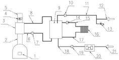
FIG. 1 is a schematic view of the industrial furnace flue gas waste heat recovery heat storage hot water heating system of the present invention;
fig. 2 is the sectional view of the flue gas waste heat recovery device of the industrial furnace flue gas waste heat recovery heat storage hot water heating system.
Fig. 3 is the utility model discloses industrial furnace flue gas waste heat recovery heat accumulation hot water heating system flue gas waste heat recovery plant top view.
In the figure:
1. industrial furnace 2, flue gas pipeline 3 and flue gas waste heat recovery equipment
4. Draught fan 5, smoke exhaust pipeline 6 and water return pipeline
7. Water pump 8, water supply pipeline 9 and heat storage water tank
10. A water pump 11, a hot water supply pipeline 12 and a tap water inlet
13. Domestic hot water supply terminal 14, water pump 15, hot water supply pipeline
16. Tail end 17 of heat radiating equipment, heat supply and water return pipeline 18 and running water supply pipe
19. Water pump 20, water softening device 21 and tap water inlet
3-1, 3-2 fins, 3-3 water outlet pipe orifices and 3-3 water inlet pipe orifices
3-4 parts of outer sleeve, 3-5 parts of upper circular steel plate and 3-6 parts of lower circular steel plate
3-7 parts of inner sleeve, 3-8 parts of inner sleeve and phase change material layer
Detailed Description
The following detailed description of the embodiments of the present invention will be made with reference to the accompanying drawings.
As shown in fig. 1 and 2, the industrial furnace flue gas waste heat recovery heat storage hot water heating system is composed of an industrial furnace 1, a flue gas pipeline 2, an induced draft fan 4, a smoke exhaust pipeline 5, flue gas waste heat recovery equipment 3, a heat storage water tank 9, a water pump 7, a water supply pipeline 8 and a water return pipeline 6. The flue gas waste heat recovery device 3 mainly comprises a flue gas pipeline 2, fins 3-1, a water inlet pipe orifice 3-2, a water outlet pipe orifice 3-3, an outer sleeve 3-4, upper and lower circular ring steel plates 3-5 and 3-6, an inner sleeve 3-7 and a medium temperature phase change material layer 3-8. The medium-temperature phase-change material layer 3-8 is smeared on the flue gas pipeline 2, and then the phase-change material is sealed by the inner sleeve 3-7. The spiral fins 3-1 are welded outside the inner sleeve 3-7, the stainless steel outer sleeve 3-4 is welded on the outer edge of the spiral fins 3-1, the circular steel plates 3-5 and 3-6 are welded between the upper surface and the lower surface of the stainless steel outer sleeve 3-4 and the flue gas pipeline 2, the water outlet pipe mouth 3-3 is arranged on the upper portion of the flue gas waste heat recovery and heat exchange device 3 along the tangential direction, and the water inlet pipe mouth 3-2 is arranged on the lower portion of the flue gas waste heat recovery and heat exchange device 3 along the tangential direction. Flue gas that industrial furnace 1 produced gets into flue gas pipeline 2, flue gas waste heat recovery device 3 and 2 flange joint of flue gas pipeline, and the flue gas is outwards discharged by exhaust pipe 5 through draught fan 4 after the cooling, is connected by water supply pipe 8 between 3 hot water outlets of flue gas waste heat recovery device and the heat storage water tank 9 top import, and high temperature water gets into heat storage water tank 9 after the heat transfer. The bottom of the heat storage water tank 9, the water pump 7 and the low-temperature water inlet of the flue gas waste heat recovery device 3 are connected by a water return pipeline 6. The low-temperature water in the heat storage water tank enters the flue gas waste heat recovery device 3 through the water pump 7 to exchange heat with the flue gas. The heat supply subsystem comprises a hot water storage tank 9, a water pump 14, a hot water supply pipeline 15, a heat dissipation equipment tail end 16 and a heat supply water return pipeline 17. High-temperature water on the upper part of the heat storage water tank 9 enters the tail end 16 of the heat dissipation device through a hot water supply pipeline 15 by a water pump 14, and low-temperature water after heat dissipation is converged and flows back to the bottom of the heat storage water tank 9 through a hot water supply return pipeline 17. The hot water supply subsystem mainly comprises a hot water storage tank 9, a water pump 10, a hot water supply pipeline 11, a tap water inlet 12 and a domestic hot water supply terminal 13. The water pump 10 pumps out high-temperature water on the upper part of the heat storage water tank 9, and the high-temperature water is mixed with tap water and is conveyed to a domestic hot water supply tail end 13 for utilization through a hot water supply pipeline 11. The tap water replenishing subsystem mainly comprises a tap water inlet 21, a water softening device 20, a water pump 19 and a tap water supply pipe 18 heat storage water tank 9. The hot water storage tank 9 is mainly replenished with softened water, and part of water used by the domestic hot water supply terminal 13 is replenished.
Under the working condition in winter, flue gas generated by the industrial furnace 1 enters the flue gas pipeline 2, the flue gas and water exchange heat in the flue gas waste heat recovery device 3 on the flue gas pipeline 2, the flue gas after being cooled is discharged outwards through the exhaust pipe 5 by the induced draft fan 4, the water after being heated enters the heat storage water tank 9, and low-temperature water in the heat storage water tank 9 enters the flue gas waste heat recovery device 3 through the water pump 7 to exchange heat with the flue gas. In the heat supply subsystem, high-temperature water on the upper part of the heat storage water tank 9 enters the tail end 16 of the heat dissipation equipment through a water pump 14, and low-temperature water after heat dissipation is converged and flows back to the bottom of the heat storage water tank 9. In the hot water supply subsystem, a water pump 10 pumps out high-temperature water on the upper part of the heat storage water tank 9, and the high-temperature water is mixed with tap water and is conveyed to a domestic hot water supply tail end 13 for utilization. The tap water replenishing subsystem is mainly used for replenishing water to the heat storage water tank 9 and replenishing part of water used by the hot water supply tail end 13.
In summer, flue gas generated by the industrial furnace 1 enters the flue gas pipeline 2, the flue gas and water exchange heat in the flue gas waste heat recovery device 3 on the flue gas pipeline 2, the flue gas is discharged outwards through the exhaust pipe 5 by the induced draft fan 4 after being cooled, the water after being heated enters the heat storage water tank 9, and low-temperature water in the heat storage water tank 9 enters the flue gas waste heat recovery device 3 through the water pump 7 to exchange heat with the flue gas. The heating subsystem stops working. In the hot water supply subsystem, a water pump 10 pumps out high-temperature water on the upper part of a heat storage water tank 9, and the high-temperature water is mixed with tap water and is conveyed to a domestic hot water supply tail end 13 for utilization. The tap water replenishing subsystem is mainly used for replenishing water to the heat storage water tank 9 and replenishing part of water used by the domestic hot water supply tail end 13.
Claims (10)
1. The utility model provides an industrial furnace flue gas waste heat recovery heat accumulation hot water heating system, includes: flue gas discharge pipeline, flue gas waste heat recovery equipment, heat storage water tank, water supply pipe and return water pipeline, characterized by: flue gas waste heat recovery equipment includes interior sleeve pipe, outer tube, phase change material layer, goes up ring steel sheet and lower ring steel sheet, phase change material layer sets up at flue gas discharge pipeline surface, interior sleeve pipe, outer tube cover form the heat dissipation cavity on flue gas discharge pipeline and are located middle temperature phase change material layer department, the last port of outer tube, lower port all are located the lateral wall of heat dissipation cavity and communicate with heat storage water tank through supply line and return water pipeline respectively, heat storage water tank lower extreme intercommunication running water supply pipe, the heat storage water tank upper end is passed through hot water supply pipeline intercommunication life hot water supply end, heat storage water tank, hot water supply pipeline, heat dissipation equipment end, heat supply return water pipeline form heat transfer return circuit.
2. The industrial furnace flue gas waste heat recovery heat storage hot water heating system as claimed in claim 1, wherein: and spiral fins are arranged between the inner sleeve and the outer sleeve.
3. The industrial furnace flue gas waste heat recovery heat storage hot water heating system as claimed in claim 1, wherein: the hot water supply pipeline is provided with a tap water replenishing pipe.
4. The industrial furnace flue gas waste heat recovery heat storage hot water heating system as claimed in claim 1, wherein: the heat storage water tank is a heat storage water tank, and the inner wall of the heat storage water tank is provided with a phase change heat storage material layer.
5. The industrial furnace flue gas waste heat recovery heat storage hot water heating system as claimed in claim 1, wherein: the tap water supply pipe is provided with a water softening device and a water pump.
6. The industrial furnace flue gas waste heat recovery heat storage hot water heating system as claimed in claim 1, wherein: and the smoke discharge pipeline is provided with a draught fan on a smoke discharge pipeline at the outlet of the smoke waste heat recovery device.
7. The industrial furnace flue gas waste heat recovery heat storage hot water heating system as claimed in claim 2, characterized in that: and a hot water supply pump is arranged on the hot water supply pipeline.
8. The industrial furnace flue gas waste heat recovery heat storage hot water heating system as claimed in claim 1, wherein: and a return water pump is arranged on the return water pipeline.
9. The industrial furnace flue gas waste heat recovery heat storage hot water heating system as claimed in claim 1, wherein: the heat storage water tank is provided with a solar photovoltaic panel heating device.
10. The industrial furnace flue gas waste heat recovery heat storage hot water heating system as claimed in claim 1, wherein: the heat storage water tank is communicated with a boiler hot water pipeline.
Priority Applications (1)
| Application Number | Priority Date | Filing Date | Title |
|---|---|---|---|
| CN201922060795.6U CN211527119U (en) | 2019-11-26 | 2019-11-26 | Industrial furnace flue gas waste heat recovery heat storage hot water heating system |
Applications Claiming Priority (1)
| Application Number | Priority Date | Filing Date | Title |
|---|---|---|---|
| CN201922060795.6U CN211527119U (en) | 2019-11-26 | 2019-11-26 | Industrial furnace flue gas waste heat recovery heat storage hot water heating system |
Publications (1)
| Publication Number | Publication Date |
|---|---|
| CN211527119U true CN211527119U (en) | 2020-09-18 |
Family
ID=72463863
Family Applications (1)
| Application Number | Title | Priority Date | Filing Date |
|---|---|---|---|
| CN201922060795.6U Expired - Fee Related CN211527119U (en) | 2019-11-26 | 2019-11-26 | Industrial furnace flue gas waste heat recovery heat storage hot water heating system |
Country Status (1)
| Country | Link |
|---|---|
| CN (1) | CN211527119U (en) |
Cited By (2)
| Publication number | Priority date | Publication date | Assignee | Title |
|---|---|---|---|---|
| CN115095904A (en) * | 2022-06-09 | 2022-09-23 | 重庆清研理工智能控制技术研究院有限公司 | Regional sanitary hot water supply system and method utilizing waste heat resources |
| CN115289860A (en) * | 2022-07-05 | 2022-11-04 | 广东世纪青山镍业有限公司 | Laterite-nickel ore smelting furnace |
-
2019
- 2019-11-26 CN CN201922060795.6U patent/CN211527119U/en not_active Expired - Fee Related
Cited By (2)
| Publication number | Priority date | Publication date | Assignee | Title |
|---|---|---|---|---|
| CN115095904A (en) * | 2022-06-09 | 2022-09-23 | 重庆清研理工智能控制技术研究院有限公司 | Regional sanitary hot water supply system and method utilizing waste heat resources |
| CN115289860A (en) * | 2022-07-05 | 2022-11-04 | 广东世纪青山镍业有限公司 | Laterite-nickel ore smelting furnace |
Similar Documents
| Publication | Publication Date | Title |
|---|---|---|
| CN211527119U (en) | Industrial furnace flue gas waste heat recovery heat storage hot water heating system | |
| CN203796339U (en) | Waste heat recovery device of direct air cooling unit | |
| CN109974492A (en) | A kind of unpowered Phase cooling system | |
| CN207279990U (en) | Solar water steam generator system | |
| CN201885448U (en) | Solar energy heat collection device | |
| WO2022174571A1 (en) | Vertical-axis wind turbine heat supply and storage system based on stirring heating | |
| CN201828020U (en) | Solar-air double-heat source type heat pump water heater | |
| CN203629059U (en) | Solar integrated water heater with fuel gas auxiliary | |
| CN204478553U (en) | The two heat-exchange system inner bag storage tank of a kind of pressure-bearing type enamel | |
| CN209944466U (en) | Single-well circulation geothermal heating system | |
| CN107202451A (en) | A kind of residents multipotency source absorption type capillary network refrigeration system | |
| CN208832758U (en) | Solar-electricity heat boiler | |
| CN207729834U (en) | A kind of environment-protecting industrial hot-water supply device | |
| CN209263110U (en) | Solar heat pump combined heated device | |
| CN201680592U (en) | Water temperature preheating device of gas water heater | |
| CN207779193U (en) | A kind of energy storage thermal desorption system | |
| CN207701210U (en) | A kind of jet dynamic control tail gas waste heat utilizing device | |
| CN207184421U (en) | A kind of BIPV system | |
| CN206724513U (en) | A kind of residents multipotency source absorption type capillary network refrigeration system | |
| CN201909384U (en) | Solar-energy auxiliary gas heating system | |
| CN207112994U (en) | Storing energy and supplying hot system | |
| CN206944286U (en) | The heating system of heat pump and power plant cycle water coincidence | |
| CN206310939U (en) | A kind of double-refrigerant separate heat pipe flue gas waste heat recovery apparatus | |
| CN206362210U (en) | A kind of low temperature exhaust heat reclaims electricity generation system | |
| CN207610422U (en) | A kind of high-efficiency and energy-saving type air source heat pump |
Legal Events
| Date | Code | Title | Description |
|---|---|---|---|
| GR01 | Patent grant | ||
| GR01 | Patent grant | ||
| CF01 | Termination of patent right due to non-payment of annual fee | ||
| CF01 | Termination of patent right due to non-payment of annual fee |
Granted publication date: 20200918 |