CN211385304U - Net piece waste material pulverizer - Google Patents
Net piece waste material pulverizer Download PDFInfo
- Publication number
- CN211385304U CN211385304U CN201922241188.XU CN201922241188U CN211385304U CN 211385304 U CN211385304 U CN 211385304U CN 201922241188 U CN201922241188 U CN 201922241188U CN 211385304 U CN211385304 U CN 211385304U
- Authority
- CN
- China
- Prior art keywords
- knife
- crushing
- blade
- cutter
- main shaft
- Prior art date
- Legal status (The legal status is an assumption and is not a legal conclusion. Google has not performed a legal analysis and makes no representation as to the accuracy of the status listed.)
- Active
Links
Images


Landscapes
- Crushing And Pulverization Processes (AREA)
Abstract
The utility model provides a net piece waste material pulverizer, which comprises a pulverizer casing, wherein a pulverizing chamber is arranged in the pulverizer casing, a cover is arranged at the top of the pulverizer casing, a main shaft is arranged in the pulverizing chamber, one end of the main shaft passes through the pulverizer casing and is connected with a power wheel, a pulverizing feed inlet is arranged at the upper part of the cover at the other end of the main shaft, a shaft sleeve is arranged on the main shaft, a connecting knife arm is fixed on the outer peripheral surface of the shaft sleeve, the outer end of the connecting knife arm is expanded to form a knife arm air plate, a tooth knife arm is fixed on the outer side of the knife arm air plate at one side of the pulverizing feed inlet, a lateral knife blade is arranged on the; the cover top is equipped with crushing export, and the cover top in crushing exit is connected with row material pipe, arranges the material pipe exit and is connected with the separation barrel. Make the crushed aggregates crushing effect better after this scheme of adoption, modular structure is convenient for change and is maintained.
Description
Technical Field
The utility model belongs to the technical field of the fishing net technique and specifically relates to indicate a net piece waste material pulverizer.
Background
The clout and the waste material that the fishing net cut off in process of production need collect the back and smash into fiber raw materials once more to reach cyclic utilization's purpose, current net piece clout is smashed and is adopted circular saw bit (blade) greatly, and this kind of blade tooth is little, and the clout hangs the tooth easily, needs the monoblock to be changed when blade wearing and tearing simultaneously, has increaseed clout treatment cost.
Disclosure of Invention
An object of the utility model is to overcome the not enough of prior art, provide a smash effectual, be convenient for change and the mesh piece waste material pulverizer who maintains.
In order to achieve the above object, the present invention provides a technical solution: a mesh waste material pulverizer comprises a pulverizer shell, wherein a pulverizing chamber is arranged in the pulverizer shell, a cover is arranged at the top of the pulverizer shell and is positioned above the pulverizing chamber, a main shaft is arranged in the pulverizing chamber, one end of the main shaft penetrates through the pulverizer shell and is connected with a power wheel, the power wheel is driven by an external pulverizing motor to operate, a pulverizing feed inlet is formed in the upper portion of the cover at the other end of the main shaft, a shaft sleeve is arranged on the main shaft, connecting knife arms are fixed on the outer peripheral surface of the shaft sleeve, the number of the connecting knife arms is four, the connecting knife arms are uniformly distributed on the outer peripheral surface of the shaft sleeve by taking the center of the main shaft as the circle center, the outer ends of the connecting knife arms are expanded to form knife arm air plates, a toothed knife arm is fixed on the outer side of the knife arm air; the cover top is equipped with crushing export, and the cover top in crushing exit is connected with row material pipe, arranges the material pipe exit and is connected with the separation barrel.
The separation cylinder be vertical tube-shape, separation cylinder upper portion one side and row material pipe exit linkage, separation cylinder upper portion opposite side is equipped with the fibre export, is connected with the fibre on the separation cylinder in the fibre export outside and collects the bag, the separation cylinder bottom shrinks gradually and forms the coarse fodder surge drum, coarse fodder surge drum bottom exit is connected with the return pipe, the return pipe export extends to crushing feed inlet top.
The bottom of the inner cavity of the crushing chamber is provided with an arc-shaped crushing screen, the inner arc surface of the crushing screen faces upwards, and a throwing area is reserved between the crushing screen and the end part of the air plate of the knife arm.
The end part of the outer end of the cutter arm air plate is provided with teeth for crushing materials, a lateral cutter disc is fixed on the main shaft outside the shaft sleeve and fixed at the end part of the shaft sleeve, the inner end of the cutter arm air plate is contacted with the edge of the lateral cutter disc, the outer end of the tooth cutter arm is connected with the cutter arm air plate, the inner end of the tooth cutter arm is connected with the lateral cutter disc, tooth cutter blades are fixed between the inner sides of adjacent tooth cutter arms, and lateral blades are installed on the outer sides of the tooth cutter arms; a T shape is formed between the lateral blade and the connecting blade arm, the lateral blade is a T-shaped cross arm, and a cutting edge is arranged on one side of the lateral blade.
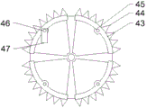
The serrated knife blade is fan-shaped, the end part of the serrated knife blade is outwards bent to form a connecting plate, the connecting plate is connected with the outer end of the serrated knife arm, chopping teeth are arranged on the outer arc surface of the serrated knife blade, a chopping knife hinge block is formed by extending the center of the inner arc surface of the serrated knife blade, a chopping knife shaft is fixed on the chopping knife hinge block, and a chopping knife blade is movably mounted on the chopping knife shaft.
After the scheme is adopted, the mesh waste material enters the crushing chamber through the crushing feed inlet, the external crushing motor drives the main shaft to rotate, the lateral blade is positioned on one side of the feeding, the mesh residual material is firstly cut into small sections through the lateral blade after entering the crusher, then the circular cutting is carried out through the tooth blade, the circular cutting is carried out and then enters between the adjacent connecting knife arms (knife arm air plates), a buffering and crushing area is arranged between the adjacent connecting knife arms (knife arm air plates), the connecting knife arms (knife arm air plates) can generate wind power during the operation, the mesh crushed material after being cut into small sections is disorderly thrown up under the action of the wind power, the crushed material flows disorderly in the crushing chamber and is crushed through the crushed material teeth in the process of throwing up and flowing, the powder (fiber) crushed to a certain degree upwards flows into the sorting cylinder through the crushing outlet and the discharging pipe along with the wind, the sorting cylinder sorts the powder (fiber) after entering, heavier powder (the piece that does not decompose completely) descends through the coarse fodder collecting vessel collection under the dead weight, send to crushing feed inlet by the return pipe at last and circulate and smash, this scheme adopts the combination of four blocks of serrated knife blades to form annular serrated knife, cut up the serrated tooth and adopt the big tooth, serrated knife blade arc length 20-30cm, it is 8-10 to cut up the serrated tooth, it beats the crushed aggregates to hit the unordered beating of garrulous blade, thereby make crushed aggregates crushing effect better, modular structure is convenient for change and maintain, it makes crushing effect better to hit the serrated tooth.
Drawings
Fig. 1 is a schematic view of the overall structure of the present invention.
Fig. 2 is a schematic view of the inside of the pulverizing chamber of the present invention.
Fig. 3 is a schematic structural view of the serrated knife blade of the present invention.
Detailed Description
The present invention will be further explained with reference to the drawings, and the preferred embodiment of the present invention is: referring to fig. 1 to 3, the mesh waste crusher of the present embodiment includes a crusher housing 51, a crushing chamber is disposed in the crusher housing 51, a cover 52 is disposed on the top of the crusher housing 51, the cover 52 is disposed above the crushing chamber, a main shaft 31 is disposed in the crushing chamber, one end of the main shaft 31 passes through the crusher housing 51 and is connected to a power wheel 53, the power wheel 53 is driven by an external crushing motor to operate, a crushing inlet is disposed on the upper portion of the cover 52 at the other end of the main shaft 31, a shaft sleeve 32 is disposed on the main shaft 31, a connecting knife arm 33 is fixed on the outer circumferential surface of the shaft sleeve 32, four connecting knife arms 33 are provided, the main shaft 31 center is used as a circle center and is uniformly distributed on the outer peripheral surface of the shaft sleeve 32, the outer end of the connecting cutter arm 33 is expanded to form a cutter arm air plate 34, an arc-shaped crushing screen 56 is installed at the bottom of the inner cavity of the crushing chamber, the inner arc surface of the crushing screen 56 faces upwards, and a throwing area is reserved between the crushing screen 56 and the end part of the cutter arm air plate 34. A toothed cutter arm 42 is fixed on the outer side of the cutter arm air plate 34 on one side of the crushing feed port, a lateral blade 35 is installed on the outer side of the toothed cutter arm 42, and a toothed cutter blade 43 is installed between the inner sides of the adjacent toothed cutter arms 42; the serrated knife blade 43 is fan-shaped, the end part of the serrated knife blade 43 is bent outwards to form a connecting plate, the connecting plate is connected with the outer end of the serrated knife arm 42, chopping teeth 44 are arranged on the outer arc surface of the serrated knife blade 43, a chopping knife hinge block 45 is formed by extending the center of the inner arc surface of the serrated knife blade 43, a chopping knife shaft 46 is fixed on the chopping knife hinge block 45, and a chopping knife blade 47 is movably mounted on the chopping knife shaft 46. The end part of the outer end of the cutter arm air plate 34 is provided with crushed material teeth 37, a lateral cutter disc 36 is fixed on the main shaft 31 outside the shaft sleeve 32, the lateral cutter disc 36 is fixed at the end part of the shaft sleeve 32, the inner end of the cutter arm air plate 34 is contacted with the edge of the lateral cutter disc 36, the outer end of the tooth cutter arm 42 is connected with the cutter arm air plate 34, the inner end of the tooth cutter arm 42 is connected with the lateral cutter disc 36, tooth cutter blades 43 are fixed between the inner sides of adjacent tooth cutter arms 42, and lateral blades 35 are installed outside the tooth cutter arm 42; a T shape is formed between the lateral blade 35 and the connecting arm 33, the lateral blade 35 is a T-shaped cross arm, and one side of the lateral blade 35 is provided with a cutting edge. Cover 52 top is equipped with smashes the export, cover 52 top in crushing exit is connected with row material pipe 54, row material pipe 54 exit is connected with a separation tube 55, separation tube 55 is vertical tube-shape, separation tube 55 upper portion one side with arrange material pipe 54 exit linkage, separation tube 55 upper portion opposite side is equipped with the fibre export, be connected with fibre collection bag 58 on the separation tube 55 in the fibre export outside, separation tube 55 bottom shrinks gradually and forms coarse fodder surge drum 57, coarse fodder surge drum 57 bottom exit is connected with the return pipe, the return pipe export extends to crushing feed inlet top.
The mesh waste material of the embodiment enters a crushing chamber through a crushing feed port, an external crushing motor drives a main shaft to rotate, a lateral blade is positioned on one side of feeding, after the mesh waste material enters a crusher, the mesh waste material is firstly cut into small pieces through the lateral blade, then the circular cutting is carried out through a tooth blade, the circular cutting enters between adjacent connecting knife arms (knife arm air plates), a buffering crushing area is arranged between the adjacent connecting knife arms (knife arm air plates), the connecting knife arms (knife arm air plates) can generate wind power during operation, the mesh crushed material cut into small pieces is disorderly thrown up under the action of the wind power, the mesh crushed material moves disorderly in the crushing chamber, the crushed material is crushed through crushed material teeth during the throwing up and floating process, the powder (fiber) crushed to a certain degree is thrown up along with the wind and enters a sorting barrel through a crushing outlet and a discharging pipe, the sorting barrel sorts the powder (fiber) after entering, and heavier powder (incompletely decomposed fragments) falls down under the dead weight and is collected through a coarse material collecting barrel, and finally, the material is sent into a crushing feed port by a return pipe to be circularly crushed, the scheme adopts the combination of four toothed cutter blades to form an annular toothed cutter, the crushing teeth adopt large teeth, the arc length of one toothed cutter blade is 20-30cm, the number of the crushing teeth is 8-10, and the crushing blades strike crushed materials disorderly, so that the crushed materials have better crushing effect, the combined structure is convenient to replace and maintain, and the crushing teeth have better crushing effect.
The above-mentioned embodiments are only preferred embodiments of the present invention, and the scope of the present invention is not limited thereto, so that all the changes made according to the shape and principle of the present invention should be covered within the protection scope of the present invention.
Claims (5)
1. The utility model provides a net piece waste material rubbing crusher, it is including rubbing crusher shell (51), is equipped with the disintegrating chamber in rubbing crusher shell (51), and rubbing crusher shell (51) top is equipped with cover (52), and cover (52) are located disintegrating chamber top, and the disintegrating chamber is indoor to install main shaft (31), and main shaft (31) wherein one end is passed rubbing crusher shell (51) and is connected with power wheel (53), and power wheel (53) are driven the operation by outside disintegrating motor, its characterized in that: a crushing feed port is formed in the upper portion of a machine cover (52) at the other end of a main shaft (31), a shaft sleeve (32) is installed on the main shaft (31), connecting knife arms (33) are fixed on the outer peripheral surface of the shaft sleeve (32), four connecting knife arms (33) are arranged, the connecting knife arms are uniformly distributed on the outer peripheral surface of the shaft sleeve (32) by taking the center of the main shaft (31) as a circle center, the outer ends of the connecting knife arms (33) are expanded to form knife arm air plates (34), toothed knife arms (42) are fixed on the outer sides of the knife arm air plates (34) on one side of the crushing feed port, lateral blades (35) are installed on the outer sides of the toothed knife arms (42), and toothed knife blades (; the top of the cover (52) is provided with a crushing outlet, the top of the cover (52) at the crushing outlet is connected with a material discharging pipe (54), and the outlet of the material discharging pipe (54) is connected with a separation barrel (55).
2. The mesh scrap shredder according to claim 1, wherein: sorting barrel (55) are vertical tube-shape, sorting barrel (55) upper portion one side and row material pipe (54) exit linkage, sorting barrel (55) upper portion opposite side is equipped with the fibre export, be connected with fibre collecting bag (58) on sorting barrel (55) in the fibre export outside, and sorting barrel (55) bottom shrinks gradually and forms coarse fodder collecting cylinder (57), and coarse fodder collecting cylinder (57) bottom exit is connected with the return pipe, and the return pipe export extends to crushing feed inlet top.
3. The mesh scrap shredder according to claim 1, wherein: an arc-shaped crushing screen (56) is installed at the bottom of the inner cavity of the crushing chamber, the inner arc surface of the crushing screen (56) faces upwards, and a throwing area is reserved between the crushing screen (56) and the end part of the knife arm air plate (34).
4. The mesh scrap shredder according to claim 1, wherein: the end part of the outer end of the cutter arm air plate (34) is provided with crushed material teeth (37), a lateral cutter head (36) is fixed on the main shaft (31) outside the shaft sleeve (32), the lateral cutter head (36) is fixed on the end part of the shaft sleeve (32), the inner end of the cutter arm air plate (34) is in contact with the edge of the lateral cutter head (36), the outer end of the cutter arm (42) is connected with the cutter arm air plate (34), the inner end of the cutter arm (42) is connected with the lateral cutter head (36), a cutter blade (43) is fixed between the inner sides of adjacent cutter arms (42), and a lateral cutter blade (35) is arranged on the outer side of each cutter arm (42); a T shape is formed between the lateral blade (35) and the connecting knife arm (33), the lateral blade (35) is a T-shaped cross arm, and a cutting edge is arranged on one side of the lateral blade (35).
5. The mesh scrap shredder according to claim 1, wherein: the serrated knife blade (43) is fan-shaped, the end part of the serrated knife blade (43) is bent outwards to form a connecting plate, the connecting plate is connected with the outer end of the serrated knife arm (42), the outer arc surface of the serrated knife blade (43) is provided with cutting serrated teeth (44), the center of the inner arc surface of the serrated knife blade (43) extends to form a chopping knife hinged block (45), a chopping knife shaft (46) is fixed on the chopping knife hinged block (45), and a chopping knife blade (47) is movably mounted on the chopping knife shaft (46).
Priority Applications (1)
| Application Number | Priority Date | Filing Date | Title |
|---|---|---|---|
| CN201922241188.XU CN211385304U (en) | 2019-12-15 | 2019-12-15 | Net piece waste material pulverizer |
Applications Claiming Priority (1)
| Application Number | Priority Date | Filing Date | Title |
|---|---|---|---|
| CN201922241188.XU CN211385304U (en) | 2019-12-15 | 2019-12-15 | Net piece waste material pulverizer |
Publications (1)
| Publication Number | Publication Date |
|---|---|
| CN211385304U true CN211385304U (en) | 2020-09-01 |
Family
ID=72225946
Family Applications (1)
| Application Number | Title | Priority Date | Filing Date |
|---|---|---|---|
| CN201922241188.XU Active CN211385304U (en) | 2019-12-15 | 2019-12-15 | Net piece waste material pulverizer |
Country Status (1)
| Country | Link |
|---|---|
| CN (1) | CN211385304U (en) |
-
2019
- 2019-12-15 CN CN201922241188.XU patent/CN211385304U/en active Active
Similar Documents
| Publication | Publication Date | Title |
|---|---|---|
| CN211739597U (en) | Novel ice crusher | |
| CN207079676U (en) | Novel garbage disposal unit | |
| CN206356104U (en) | A kind of multi-functional Kiwi berry pulper | |
| CN112934384A (en) | Financial finance is bill reducing mechanism for accounting | |
| CN201192651Y (en) | Electric broken-leaf machine | |
| CN211385304U (en) | Net piece waste material pulverizer | |
| CN106984395B (en) | Forage grass pulverizer with three pulverizing chambers | |
| CN214514836U (en) | Cardboard recovery unit is used in carton processing | |
| CN210614623U (en) | Concrete waste material stirs garrulous device of utilizing | |
| KR101389577B1 (en) | A crusher for waste food | |
| CN211386269U (en) | Fishing net production clout cyclic utilization system | |
| CN206526887U (en) | A kind of improved Kiwi berry pulper | |
| CN214347049U (en) | Dry reducing mechanism of chinese-medicinal material | |
| CN209901434U (en) | Medicinal material scattering device | |
| CN210752964U (en) | Wormwood rubbing crusher | |
| CN208865732U (en) | Vertical extrusion formula mulberry branch pulverizer | |
| CN211385303U (en) | Fishing net clout deironing, reducing mechanism | |
| CN208711855U (en) | A kind of biomass granule fuel raw mill plant | |
| CN211385305U (en) | Fishing net sheet remainder shredding knife group | |
| CN110814001A (en) | Fishing net production clout cyclic utilization system | |
| CN217663805U (en) | Quick preparation facilities of collagen raw materials | |
| CN110773282A (en) | Biomass particle fuel raw material crushing equipment | |
| CN218784871U (en) | Medicinal material reducing mechanism | |
| CN110171079A (en) | A kind of vertical plastic pulverizer | |
| CN217569064U (en) | Crushing and smashing integrated fertilizer crusher |
Legal Events
| Date | Code | Title | Description |
|---|---|---|---|
| GR01 | Patent grant | ||
| GR01 | Patent grant |