CN211365983U - Material conveying mechanism of product water gap separator - Google Patents
Material conveying mechanism of product water gap separator Download PDFInfo
- Publication number
- CN211365983U CN211365983U CN201921950995.2U CN201921950995U CN211365983U CN 211365983 U CN211365983 U CN 211365983U CN 201921950995 U CN201921950995 U CN 201921950995U CN 211365983 U CN211365983 U CN 211365983U
- Authority
- CN
- China
- Prior art keywords
- slide
- translation
- lift
- carrying
- collet
- Prior art date
- Legal status (The legal status is an assumption and is not a legal conclusion. Google has not performed a legal analysis and makes no representation as to the accuracy of the status listed.)
- Active
Links
Images


Landscapes
- Specific Conveyance Elements (AREA)
Abstract
The utility model discloses a material transport mechanism that removes of product mouth of a river separating centrifuge, which comprises a frame, the transport holds in the palm the material track, and a support, the translation slide, translation slide translation drive arrangement, the lift slide, lift slide lift drive arrangement, first collet, the second collet and the ejector pad of unloading, the transport holds in the palm the material track and installs on the workstation of frame, the support sets up the bottom at the workstation, the translation slide slides and installs on the crossbeam of support and be connected with the translation slide translation drive arrangement transmission of installing on the crossbeam, the lift slide slides and installs on the translation slide and be connected with the lift slide lift drive arrangement transmission of installing on the translation slide, first collet, the second collet sets up the top at the lift slide with the ejector pad of unloading interval in proper order. The utility model has the advantages of reasonable design, the operation is reliable and stable, can realize the automation of work piece and remove the material transportation to carry each station with the work piece steadily, improved production efficiency greatly, can satisfy the large-scale production demand of enterprise.
Description
Technical Field
The utility model relates to an automatic change processing equipment's technical field, more specifically say, relate to a material transport mechanism that removes of product mouth of a river separating centrifuge.
Background
After injection molding of a hardware or plastic workpiece, a nozzle portion is left on the workpiece, and as shown in fig. 1, the workpiece 01 has an outer nozzle portion 011, a product portion 012 and an inner nozzle portion 013, and in a production process of the workpiece, the product portion 012 needs to be removed from the workpiece 01 in order to obtain a product. The traditional processing method adopts manual taking out, and workers need to break off the outer water gap part 011 and the inner water gap part 013 on two sides of the product part 012 or cut off by a tool, so that the method not only greatly prolongs the production period, has low efficiency and high labor intensity, but also is difficult to ensure the precision and quality of the product, and greatly reduces the qualification rate. In order to solve the above problem, it is necessary to develop an automatic product nozzle separator, and the conveying mechanism of the workpiece is one of the key mechanisms of the product nozzle separator.
SUMMERY OF THE UTILITY MODEL
An object of the utility model is to overcome the above-mentioned defect among the prior art, provide a material transport mechanism that removes of product mouth of a river separating centrifuge.
In order to achieve the above object, the utility model provides a material conveying mechanism of a product nozzle separator, which comprises a material conveying and supporting track, a support, a translation sliding seat translation driving device, a lifting sliding seat lifting driving device, a first material clamp, a second material clamp and a discharging push block, wherein the material conveying and supporting track is arranged on a worktable of a frame, the support is arranged at the bottom of the worktable, the translation sliding seat is transversely and slidably arranged on a cross beam of the support through a first sliding rail block component, the translation sliding seat translation driving device is arranged on the cross beam of the support and is in transmission connection with the translation sliding seat so as to drive the translation sliding seat to translate along the direction parallel to a conveying groove path of the material conveying and supporting track, the lifting sliding seat is vertically and slidably arranged on the translation sliding seat through a second sliding rail block component and is in transmission connection with the lifting sliding seat lifting driving device arranged on the, the first material clamp, the second material clamp and the discharging push block are sequentially arranged at the top of the lifting slide seat at intervals along the feeding direction, and the tops of the first material clamp, the second material clamp and the discharging push block can penetrate through the workbench to extend into a conveying groove of the conveying material supporting rail.
As a preferred embodiment, the translation sliding seat translation driving device comprises a screw rod, a screw rod driving motor, a nut seat and a connecting block connected with the nut seat, the screw rod is transversely arranged on a cross beam of the support and is driven by the screw rod driving motor arranged at one end of the cross beam, and the nut seat is in transmission connection with the screw rod and is fixedly connected with the translation sliding seat through the connecting block.
As preferred embodiment, lift slide lift drive arrangement sets up to lift slide lift and drives actuating cylinder, lift slide lift is driven actuating cylinder and is vertically installed on the side of translation slide through the fixing base, lift slide lift and drive actuating cylinder's output shaft through the card go into the joint and the lift slide fixed connection of lift slide.
In a preferred embodiment, the lateral surface of the translation carriage is provided with a buffer located below the lifting carriage, said buffer being able to come into contact with the bottom of the lifting carriage.
In a preferred embodiment, the material carrying rail is composed of two parallel plate bodies, and a conveying groove for carrying the material carrying rail is formed between the two plate bodies.
As a preferred embodiment, a first positioning jig located at the feeding end of the carrying material supporting rail, a second positioning jig located at the middle position of the carrying material supporting rail, and a third positioning jig located at the discharging end of the carrying material supporting rail are respectively arranged in the conveying groove of the carrying material supporting rail, and positioning grooves for positioning workpieces are arranged at the tops of the first positioning jig, the second positioning jig, and the third positioning jig.
Compared with the prior art, the beneficial effects of the utility model reside in that:
the utility model has the advantages of reasonable design, the operation is reliable and stable, can realize the automation of work piece and remove the material transportation to carry each station with the work piece steadily, improved production efficiency greatly, can satisfy the large-scale production demand of enterprise.
Drawings
In order to more clearly illustrate the embodiments of the present invention or the technical solutions in the prior art, the drawings needed to be used in the description of the embodiments or the prior art will be briefly described below, and it is obvious that the drawings in the following description are some embodiments of the present invention, and for those skilled in the art, other drawings can be obtained according to these drawings without creative efforts.
Fig. 1 is a schematic structural diagram of a workpiece according to an embodiment of the present invention;
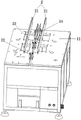
fig. 2 is a schematic structural diagram of a material conveying mechanism of a product nozzle separator according to an embodiment of the present invention;
fig. 3 is a schematic structural diagram of a material carrying track portion of a material carrying and transporting mechanism of a product nozzle separator according to an embodiment of the present invention;
fig. 4 is a schematic structural view of a first positioning jig or a second positioning jig of a material conveying and transporting mechanism of a product nozzle separator according to an embodiment of the present invention;
fig. 5 is a schematic structural view of a third positioning fixture of the material conveying mechanism of the product nozzle separator according to the embodiment of the present invention;
fig. 6 is a schematic view of a main structure of a material conveying and transporting mechanism according to an embodiment of the present invention;
fig. 7 is a schematic structural diagram of a main body of the material conveying and transporting mechanism according to the embodiment of the present invention;
fig. 8 is a schematic structural diagram three of the main body of the material conveying and transporting mechanism provided in the embodiment of the present invention.
Detailed Description
In order to make the objects, technical solutions and advantages of the embodiments of the present invention clearer, the embodiments of the present invention will be clearly and completely described below with reference to the accompanying drawings in the embodiments of the present invention, and it is obvious that the described embodiments are some, but not all, embodiments of the present invention. Based on the embodiments in the present invention, all other embodiments obtained by a person skilled in the art without creative efforts belong to the protection scope of the present invention.
Referring to fig. 2 to 8, an embodiment of the present invention provides a material conveying mechanism of a product nozzle separator, which includes a frame 1, a material conveying rail 2, a support 3, a translation slide 4, a translation slide translation driving device 5, a lifting slide 6, a lifting slide lifting driving device 7, a first material clamp 8, a second material clamp 9, and a discharging push block 10, and each component of the embodiment is described in detail with reference to the drawings.
The material carrying track 2 is arranged on a workbench 11 of the frame 1, the bracket 3 is arranged at the bottom of the workbench 11, the translation slide seat 4 is transversely arranged on a beam of the bracket 3 in a sliding way through a first slide rail and slide block component 12, the translation slide seat translation driving device 5 is arranged on the beam of the bracket 3 and is in transmission connection with the translation slide seat 4, so as to drive the translation slide 4 to translate along the direction of the conveying trough path parallel to the conveying material supporting track 2, the lifting slide 6 can be installed on the translation slide 4 through the second slide rail and slide block assembly 13 in a vertical sliding manner and is in transmission connection with the lifting slide lifting drive device 7 installed on the translation slide 4, the first material clamp 8, the second material clamp 9 and the discharging push block 10 are sequentially arranged at the top of the lifting slide 6 at intervals along the feeding direction, and the top of the first material clamp 8, the top of the second material clamp 9 and the discharging push block 10 can penetrate through the working table 11 and extend into the conveying trough of the conveying material supporting track 2.
As shown in fig. 3, 4 and 5, the carrying and supporting rail 2 may be composed of two plate bodies 21 parallel to each other, a conveying groove for carrying and supporting the rail 2 is formed between the two plate bodies 21, a first positioning jig 22 located at a feeding end of the carrying and supporting rail 2, a second positioning jig 23 located at a middle position of the carrying and supporting rail 2, and a third positioning jig 24 located at a discharging end of the carrying and supporting rail 2 may be respectively disposed in the conveying groove for carrying and supporting the rail 2, and positioning grooves for positioning workpieces are disposed at tops of the first positioning jig 22, the second positioning jig 23, and the third positioning jig 24.
Preferably, the translation slide translation driving device 5 may include a lead screw 51, a lead screw driving motor 52, a nut seat 53 and a connecting block 54 connected with the nut seat, the lead screw 51 is transversely installed on a cross beam of the bracket 3 and is driven by the lead screw driving motor 52 installed at one end of the cross beam, and the nut seat 53 is in transmission connection with the lead screw 51 and is fixedly connected with the translation slide 4 through the connecting block 54.
Further, the lifting slide seat lifting driving device 7 can be set as a lifting slide seat lifting driving cylinder, the lifting slide seat lifting driving cylinder is longitudinally arranged on the side surface of the translation slide seat 4 through a fixing seat 14, and an output shaft of the lifting slide seat lifting driving cylinder is fixedly connected with the lifting slide seat 6 through a clamping head 15 clamped into the lifting slide seat 6.
In order to enable the material conveying mechanism to operate more stably and safely, two buffers 16 located below the lifting slide 6 can be arranged on the side surface of the translation slide 4, and the buffers 16 are common oil buffers on the market. When the lifting slide seat 6 descends to be close to the in-place position, the top of the lifting slide seat 6 can be in contact with the buffer 16, so that the buffering effect is achieved, the impact force on the lifting slide seat lifting driving cylinder when the lifting slide seat 6 descends is reduced, and the service life of the lifting slide seat lifting driving cylinder is prolonged.
As shown in fig. 8, a protective cover 17 may be provided on a cross beam of the rack 3 to protect the screw position of the material conveying mechanism.
When a worker or a manipulator places a workpiece at one end of the carrying and supporting track, the lifting slide seat can lift and drive the air cylinder to drive the first material clamp, the second material clamp and the unloading push block to rise, so that the first material clamp and the second material clamp respectively clamp the workpiece at each station on the carrying and supporting track, the unloading push block extends to the side edge of the workpiece tail at the discharging end of the carrying and supporting track, then the translation slide seat translation driving device drives the first material clamp, the second material clamp and the unloading push block to move transversely, so that the first material clamp and the second material clamp respectively bring the respectively clamped workpieces to the next station, the unloading push block pushes the workpiece tail out of the carrying and supporting track, and the automatic carrying and conveying of the workpieces are completed.
To sum up, the utility model has the advantages of reasonable design, the operation is reliable and stable, can realize the automation of work piece and remove the material transportation to carry each station with the work piece steadily, improved production efficiency greatly, can satisfy the scale production demand of enterprise.
The above embodiments are preferred embodiments of the present invention, but the embodiments of the present invention are not limited to the above embodiments, and any other changes, modifications, substitutions, combinations, and simplifications which do not depart from the spirit and principle of the present invention should be equivalent replacement modes, and all are included in the scope of the present invention.
Claims (6)
1. The utility model provides a material transport mechanism that removes of product mouth of a river separating centrifuge which characterized in that: including carrying material supporting rail (2), support (3), translation slide (4), translation slide translation drive arrangement (5), lift slide (6), lift slide lift drive arrangement (7), first collet (8), second collet (9) and ejector pad (10) of unloading, carrying material supporting rail (2) is installed on workstation (11) of frame (1), support (3) set up the bottom at workstation (11), but translation slide (4) are installed on the crossbeam of support (3) through first slide rail sliding block set (12) lateral sliding, but translation slide translation drive arrangement (5) are installed on the crossbeam of support (3) and are connected with translation slide (4) transmission to drive translation slide (4) along the conveyer trough route direction translation that is on a parallel with carrying material supporting rail (2), but lift slide (6) are installed through second slide rail sliding block set (13) and can be up and down slided translation slide (4) Go up and be connected with lift slide lift drive arrangement (7) transmission of installing on translation slide (4), first collet (8), second collet (9) and ejector pad (10) of unloading set up the top at lift slide (6) along the pay-off direction interval in proper order, the top homoenergetic of first collet (8), second collet (9) and ejector pad (10) of unloading can pass during workstation (11) stretches into the conveyer trough of transport material supporting track (2).
2. The material conveying mechanism of the product nozzle separator as claimed in claim 1, wherein: translation slide translation drive arrangement (5) include lead screw (51), lead screw driving motor (52), nut seat (53) and link together connecting block (54) with nut seat (53), lead screw (51) are transversely installed on the crossbeam of support (3) and are driven by lead screw driving motor (52) of installing the one end at the crossbeam, nut seat (53) are connected and pass through connecting block (54) and translation slide (4) fixed connection with lead screw (51) transmission.
3. The material conveying mechanism of the product nozzle separator as claimed in claim 1, wherein: lifting slide lift drive arrangement (7) set up to lifting slide lift and drive actuating cylinder, lifting slide lift and drive actuating cylinder vertically install on the side of translation slide (4) through fixing base (14), lifting slide lift and drive actuating cylinder's output shaft through the card go into joint (15) and lifting slide (6) fixed connection in lifting slide (6).
4. The material conveying mechanism of the product nozzle separator as claimed in claim 1, wherein: the side of the translation sliding seat (4) is provided with a buffer (16) positioned below the lifting sliding seat (6), and the buffer (16) can be in contact with the bottom of the lifting sliding seat (6).
5. The material conveying mechanism of the product nozzle separator as claimed in claim 1, wherein: the material carrying rail (2) is composed of two parallel plate bodies (21), and a conveying groove for carrying the material carrying rail (2) is formed between the two plate bodies (21).
6. The material conveying mechanism of the product nozzle separator as claimed in claim 1, wherein: the conveying device is characterized in that a first positioning jig (22) located at a feeding end of the carrying and supporting rail (2), a second positioning jig (23) located at the middle position of the carrying and supporting rail (2) and a third positioning jig (24) located at a discharging end of the carrying and supporting rail (2) are respectively arranged in a conveying groove of the carrying and supporting rail (2), and positioning grooves for positioning workpieces are formed in the tops of the first positioning jig (22), the second positioning jig (23) and the third positioning jig (24).
Priority Applications (1)
| Application Number | Priority Date | Filing Date | Title |
|---|---|---|---|
| CN201921950995.2U CN211365983U (en) | 2019-11-13 | 2019-11-13 | Material conveying mechanism of product water gap separator |
Applications Claiming Priority (1)
| Application Number | Priority Date | Filing Date | Title |
|---|---|---|---|
| CN201921950995.2U CN211365983U (en) | 2019-11-13 | 2019-11-13 | Material conveying mechanism of product water gap separator |
Publications (1)
| Publication Number | Publication Date |
|---|---|
| CN211365983U true CN211365983U (en) | 2020-08-28 |
Family
ID=72172386
Family Applications (1)
| Application Number | Title | Priority Date | Filing Date |
|---|---|---|---|
| CN201921950995.2U Active CN211365983U (en) | 2019-11-13 | 2019-11-13 | Material conveying mechanism of product water gap separator |
Country Status (1)
| Country | Link |
|---|---|
| CN (1) | CN211365983U (en) |
Cited By (1)
| Publication number | Priority date | Publication date | Assignee | Title |
|---|---|---|---|---|
| CN114228317A (en) * | 2021-12-13 | 2022-03-25 | 潘华云 | Automatic batch silk-screen printing and drying equipment |
-
2019
- 2019-11-13 CN CN201921950995.2U patent/CN211365983U/en active Active
Cited By (2)
| Publication number | Priority date | Publication date | Assignee | Title |
|---|---|---|---|---|
| CN114228317A (en) * | 2021-12-13 | 2022-03-25 | 潘华云 | Automatic batch silk-screen printing and drying equipment |
| CN114228317B (en) * | 2021-12-13 | 2024-01-05 | 广东承兴印刷实业有限公司 | Automatic batch screen printing and drying equipment |
Similar Documents
| Publication | Publication Date | Title |
|---|---|---|
| KR102585379B1 (en) | Double station gantry complex machining system with automatic turning of workpieces | |
| CN109623929B (en) | Automatic chamfering device for sealing ring | |
| CN214394865U (en) | Flaw-piece discharging mechanism and silicon rod processing equipment | |
| CN209716652U (en) | A kind of automobile internal spherical cage cutting special equipment | |
| CN108620930B (en) | Full-automatic bar processing machine tool | |
| CN102729100A (en) | Double-main-shaft machine tool, installing and dismounting method thereof | |
| CN211365983U (en) | Material conveying mechanism of product water gap separator | |
| KR20210150445A (en) | Multi-spindle fully automatic vertical machining center | |
| CN110884072A (en) | Product water gap separator | |
| CN108857791B (en) | Bilateral grinding device for automobile part crankshaft connecting rod | |
| CN209986498U (en) | Front cover automatic feeding and riveting device for automatic assembly of drill chuck | |
| CN209969705U (en) | Mechanical plate shearing machine | |
| CN109848582B (en) | Three-dimensional laser cutting machine of panel of bending | |
| CN108581802B (en) | Automatic polishing machine with shearing function | |
| CN108326977B (en) | Feeding device of sheet processing equipment | |
| CN212147383U (en) | Product water gap separator | |
| CN204770774U (en) | Automatic horizontal multistation lathe of unloading | |
| CN210755536U (en) | High-efficiency circular sawing machine | |
| CN209986499U (en) | Front sleeve automatic feeding and riveting device for automatic assembly of drill chuck | |
| CN108857722B (en) | Crankshaft connecting rod double-side grinding machine | |
| CN113427357A (en) | Metal shell polishing system and polishing method thereof | |
| CN109759568B (en) | Automatic discharging device for part machining | |
| CN108908041B (en) | Machining device for double-side grinding of automobile part crankshaft connecting rod | |
| CN108381351B (en) | Automatic grinding machine for double-station diamond tool bit welding surface | |
| CN204894068U (en) | Section bar saw cuts discharge apparatus of equipment |
Legal Events
| Date | Code | Title | Description |
|---|---|---|---|
| GR01 | Patent grant | ||
| GR01 | Patent grant |