CN211309741U - Lifting assembly for changing layers of multilayer shuttle - Google Patents
Lifting assembly for changing layers of multilayer shuttle Download PDFInfo
- Publication number
- CN211309741U CN211309741U CN201921023985.4U CN201921023985U CN211309741U CN 211309741 U CN211309741 U CN 211309741U CN 201921023985 U CN201921023985 U CN 201921023985U CN 211309741 U CN211309741 U CN 211309741U
- Authority
- CN
- China
- Prior art keywords
- wheel
- guide wheel
- synchronous belt
- constraint guide
- carrying platform
- Prior art date
- Legal status (The legal status is an assumption and is not a legal conclusion. Google has not performed a legal analysis and makes no representation as to the accuracy of the status listed.)
- Active
Links
Images


Landscapes
- Warehouses Or Storage Devices (AREA)
Abstract
The utility model discloses a promotion subassembly that multilayer shuttle traded layer, including first, second lifting machine, shuttle. And the outer edge of the roller bracket of each elevator is provided with an orbit section, and two opposite orbit sections form two parallel orbits for the shuttle to walk together. When the shuttle car needs to walk between the two lifting machines, the goods carrying platform of the first lifting machine and the goods carrying platform of the second lifting machine are positioned at the same height, and the shuttle car is used for walking. The two sides of the two rail sections can be connected with other fixed rails in the storage space, so that the fixed rails can be omitted between the two hoists. The structure combines the hoister and the track together, and improves the storage space utilization rate.
Description
Technical Field
The utility model belongs to the warehousing and storage system field especially relates to a lifting unit who contains lifting machine that uses among storage rack.
Background
In the existing warehousing system, a lifter is adopted to lift the goods to the height of each layer of goods shelf, and the goods are taken and placed. The existing elevator comprises a vertical column and a loading platform which moves up and down along the vertical column and is used for loading a cargo bin. The upright post is provided with a lifting mechanism which can move the cargo carrying platform up and down. And a plurality of layers of tracks are arranged beside the cargo carrying platform for the shuttle car to walk, and the shuttle car assists in transporting the cargo box and taking and placing the cargo box from the cargo carrying platform.
However, in practical use, in some environments with a small storage space, if two hoists are placed, it is difficult to provide a rail fixed in the storage space in the space between the two hoists. Or, if the rail is fixed, the installation of the rail and the elevator is interfered with each other, and if the elevator or the rail needs to be replaced, the elevator and the rail between the two elevators need to be removed simultaneously, so that the difficulty and the cost of the subsequent storage system maintenance are increased.
Therefore, a new technical solution is needed to solve the above technical problems.
Disclosure of Invention
The purpose of the invention is as follows: the invention provides a lifting assembly for changing layers of a multi-layer shuttle, which can be used for combining two lifting machines and a shuttle walking track by utilizing a limited space and is convenient to disassemble and maintain.
The technical scheme is as follows: the invention can adopt the following technical scheme:
a lifting assembly for changing layers of a multi-layer shuttle car comprises the shuttle car, a first lifting machine and a second lifting machine, wherein the first lifting machine and the second lifting machine are respectively provided with an upright post, a loading platform and a lifting mechanism; the lifting mechanism comprises an upper synchronous belt wheel positioned at the top end of the upright post, a lower synchronous belt wheel positioned at the bottom of the upright post, a synchronous belt wound on the upper synchronous belt wheel and the lower synchronous belt wheel and a motor; the synchronous belt is provided with a fixing device, at least one of the upper synchronous belt wheel and the lower synchronous belt wheel is a driving wheel, and the motor drives the driving wheel to rotate; the cargo carrying platform comprises a plurality of rollers and roller brackets positioned on two sides of the rollers; and the outer edge of the roller support positioned outside the roller is provided with a track section, and when the cargo carrying platform of the first hoister and the cargo carrying platform of the second hoister are positioned at the same height, the track section on the first hoister and the track section on the second hoister are arranged in parallel and form a walking track for bearing the shuttle.
Has the advantages that: compared with the prior art, the utility model provides a lifting unit has contained two lifting machines, first, second lifting machine promptly. A fixed rail in the prior art is not arranged between the two hoists, but a rail section is arranged on the outer edge of the roller bracket of each hoist, and two opposite rail sections jointly form two parallel rails for the shuttle to travel. When the shuttle car needs to walk between the two lifting machines, the goods carrying platform of the first lifting machine and the goods carrying platform of the second lifting machine are positioned at the same height, and the shuttle car is used for walking. The two sides of the two rail sections can be connected with other fixed rails in the storage space, so that the fixed rails can be omitted between the two hoists. This structure combines lifting machine and track to be in the same place, has improved storage space utilization, simultaneously because do not have fixed track between two lifting machines, then has avoided prior art middle fixed track's interference to the dismantlement of lifting machine. The first hoisting machine and the second hoisting machine can be maintained conveniently and respectively.
Furthermore, the goods carrying platform of the first hoister and the goods carrying platform of the second hoister are arranged oppositely, and the two goods carrying platforms are lifted independently or lifted simultaneously.
Further, in first lifting machine or the second lifting machine, the stand includes two, pass through the coupling joint between the lower synchronous pulley of two stand bottoms, motor output shaft and coupling joint are connected in series and are driven two synchronous pulleys down simultaneously and rotate.
Furthermore, the goods carrying platform is provided with a fixed bracket fixed on the outer side of one roller bracket, and the fixed bracket comprises a fixed plate fixedly matched with a fixing device on the synchronous belt and a side plate positioned on the side surface of the fixed plate; the fixed plate is provided with a first opening, one side of the fixed plate, which is opposite to the upright post, is provided with a first constraint guide wheel, and the wheel surface of the first constraint guide wheel is abutted and matched with the front surface of the upright post through the first opening; a second opening is formed in the side plate, a second constraint guide wheel is arranged on one side of the side plate, which is opposite to the upright column, the axial direction of the second constraint guide wheel is vertical to the axial direction of the first constraint guide wheel, and the wheel surface of the second constraint guide wheel is abutted and matched with the side surface of the upright column through the second opening; a third constraint guide wheel opposite to the first constraint guide wheel is also arranged on the side plate, and the axial direction of the third constraint guide wheel is parallel to the axial direction of the first constraint guide wheel; the wheel surface of the third constraint guide wheel is abutted and matched with the rear surface of the upright post; the fixing plate is detachably connected with the fixing device.
Furthermore, the bottom of fixed bolster is equipped with to the roller support and the bearing frame that the roller below extends, roller support detachable sets up on bearing the frame.
Drawings
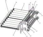
Fig. 1 is a perspective view of the lifting assembly of the present invention and shows the shuttle passing between two hoists.
Fig. 2 is a perspective view of the lift assembly of the present invention and shows the shuttle not passing between two hoists.
Fig. 3 is a perspective view of one of the hoists of the present invention.
Fig. 4 is a perspective view of the middle loading platform of the present invention.
Fig. 5 is a perspective view of the assembled center pillar and lifting mechanism of the present invention.
Detailed Description
The invention is described in further detail below with reference to the figures and the specific embodiments.
Please refer to fig. 1 and 2, the lifting assembly for changing layers of a multi-layer shuttle car provided by the present invention comprises a shuttle car 100, a first lifting machine 200, and a second lifting machine 300, wherein the first lifting machine 200 and the second lifting machine 300 are respectively provided with a column 1, a loading platform 2, and a lifting mechanism.
As shown in fig. 3 and 5, in the present embodiment, the first hoisting machine 200 and the second hoisting machine 300 are provided to face each other in the same configuration, and therefore, only one hoisting machine will be described in the following description of the configuration of the hoisting machines.
The lifting mechanism comprises an upper synchronous belt pulley 4 positioned at the top end of the upright post 1, a lower synchronous belt pulley 5 positioned at the bottom of the upright post 1, a synchronous belt 6 wound on the upper synchronous belt pulley 4 and the lower synchronous belt pulley 5, and a motor 7. The number of the upright posts 1 is at least one, and in the present embodiment, a double upright post structure commonly used in the art is selected to stably support the cargo bed 2. The synchronous belt 6 is provided with a fixing device 8, at least one of the upper synchronous belt pulley 4 and the lower synchronous belt pulley 5 is a driving wheel, namely, both the upper synchronous belt pulley 4 and the lower synchronous belt pulley 5 can be used as the driving wheel, and the motor 7 drives the driving wheel to rotate. In the present embodiment, the lower timing pulley 5 is selected as the primary pulley. The lower synchronous belt pulleys 5 at the bottom of the upright post 1 are connected through a coupler 20, and the output shaft of the motor is connected with the coupler 20 in series and drives the two lower synchronous belt pulleys 5 to rotate simultaneously.
As shown in fig. 4 and 5, the cargo bed 2 includes a plurality of rollers 9, roller brackets 10 located at both sides of the rollers 9, and a fixing bracket 11 fixed at an outer side of one roller bracket 10. The fixed bracket 11 comprises a fixed plate 12 fixedly matched with the fixing device 8 on the synchronous belt 6 and a side plate 13 positioned at the side of the fixed plate 12. Wherein, the outer edge of the roller bracket 10 positioned at the outer side of the roller 9 is provided with a track section 22. When the cargo carrying platform of the first hoist 200 and the cargo carrying platform of the second hoist 300 are located at the same height, the track sections on the first hoist 200 and the second hoist 300 are arranged in parallel and form a walking track for carrying the shuttle car 100 together. The goods carrying platform of the first hoister 200 and the goods carrying platform of the second hoister 300 are arranged oppositely, and the two goods carrying platforms lift independently or lift simultaneously. As shown in fig. 2, when the shuttle car 100 needs to travel between the two hoists 200 and 300, the cargo bed of the first hoist 200 and the cargo bed of the second hoist 300 are located at the same height (i.e., the two rail segments are located at the same height) and the shuttle car 100 travels. The two rail sections 22 may be connected on both sides to other fixed rails (not shown) in the storage space, so that no fixed rail may be provided between the two hoists. Similarly, the lengths of the two rail segments 22 may be flexibly set corresponding to different storage spaces to control the interval between the two hoists 200 and 300 and other fixed rails (not shown) to avoid installation interference. When the shuttle car 100 does not need to pass between the two hoists 200, 300, as shown in fig. 2, the loading platforms 2 of the two hoists can independently run to different heights and independently operate.
Further, the structure of the hoisting machine is further explained. As shown in fig. 3 to fig. 5, a first opening 13 is disposed on the fixing plate 12, a first constraining guide wheel 14 is disposed on a side of the fixing plate 12 opposite to the upright post 1, and a wheel surface of the first constraining guide wheel 14 is abutted against and matched with a front surface of the upright post 1 through the first opening 13. The side plate 13 is provided with a second opening 15, one side of the side plate 13, which faces away from the upright post 1, is provided with a second restraint guide wheel 16, and the axial direction of the second restraint guide wheel 16 is perpendicular to the axial direction of the first restraint guide wheel 14. The wheel surface of the second restraint guide wheel 16 is abutted and matched with the side surface of the upright post 1 through the second opening 15. The side plate 13 is also provided with a third constraining guide wheel 17 opposite to the first constraining guide wheel 14. The third idler sheave 17 is axially parallel to the first idler sheave 14. The wheel surface of the third restraint guide wheel 17 is in abutting fit with the rear surface of the upright post 1. Thereby make the location that carries cargo bed 2 and stand 1 can be quick through first, second, third restraint guide pulley, and carry cargo bed 2 when reciprocating, can follow three direction guide along the stand rotation with first, second, third restraint guide pulley and carry cargo bed 2 removal and increase the stability of removal. And between the goods carrying platform 2 and the upright post 1, the fixing plate 12 is detachably connected with the fixing device 8, for example, the fixing plate is connected with the fixing device through screws or bolts, so that the purpose of quick replacement is achieved, and the goods carrying platforms with different sizes can be replaced corresponding to different types of storage racks. Simultaneously, the positioning between the cargo carrying platform 2 and the upright post 1 after quick replacement is accurate through the positioning action of the first, second and third constraint guide wheels, so that the replacement is convenient. In this embodiment, because stand 1 is two, the fixed bolster of cargo bed includes two equally, all sets up first restraint guide pulley, second restraint guide pulley, third restraint guide pulley on every fixed bolster and with the cooperation of corresponding stand. And the number of the first restraining guide wheel, the second restraining guide wheel and the third restraining guide wheel of each fixing bracket is two. The first, second and third constraint guide wheels respectively have an assembly structure as follows: the fixed plate 12 is provided with a first support plate 18 opposite to the upright 1 and carrying the first constraining guide wheel 14, and the first support plate 18 is provided with a first rotating shaft matched with the first constraining guide wheel 14. The side plate 13 is provided with a second support plate 19 for bearing a second constraint guide wheel 16 opposite to the upright post 1, and the second support plate 19 is provided with a second rotating shaft matched with the second constraint guide wheel 16. The third idler sheave 17 is directly mounted on the side plate 13 through a third rotating shaft.
As shown in fig. 3, the bottom of the fixing bracket 11 is provided with a bearing frame 21 extending to the lower part of the roller bracket and the roller, and the roller bracket 10 is detachably arranged on the bearing frame 21. In this way, it is possible to provide two ways of dismounting only the roller holder and the roller, and dismounting the carriage in its entirety, providing more alternative replacement operations.
In addition, the present invention has many specific implementations and ways, and the above description is only a preferred embodiment of the present invention. It should be noted that, for those skilled in the art, without departing from the principle of the present invention, several improvements and modifications can be made, and these improvements and modifications should also be construed as the protection scope of the present invention.
Claims (5)
1. A lifting assembly for changing layers of a multi-layer shuttle car comprises the shuttle car, a first lifting machine and a second lifting machine, wherein the first lifting machine and the second lifting machine are respectively provided with an upright post, a loading platform and a lifting mechanism; the lifting mechanism comprises an upper synchronous belt wheel positioned at the top end of the upright post, a lower synchronous belt wheel positioned at the bottom of the upright post, a synchronous belt wound on the upper synchronous belt wheel and the lower synchronous belt wheel and a motor; the synchronous belt is provided with a fixing device, at least one of the upper synchronous belt wheel and the lower synchronous belt wheel is a driving wheel, and the motor drives the driving wheel to rotate; the cargo carrying platform comprises a plurality of rollers and roller brackets positioned on two sides of the rollers; the method is characterized in that: and the outer edge of the roller support positioned outside the roller is provided with a track section, and when the cargo carrying platform of the first hoister and the cargo carrying platform of the second hoister are positioned at the same height, the track section on the first hoister and the track section on the second hoister are arranged in parallel and form a walking track for bearing the shuttle.
2. The multi-deck shuttle car layer change lift assembly of claim 1, wherein: the goods carrying platform of the first hoister and the goods carrying platform of the second hoister are arranged oppositely, and the two goods carrying platforms independently lift or lift simultaneously.
3. The multi-deck shuttle car layer change lift assembly of claim 2, wherein: in first lifting machine or the second lifting machine, the stand includes two, through the coupling joint between the lower synchronous pulley of two stand bottoms, motor output shaft and coupling joint are connected in series and are driven two synchronous pulleys simultaneously and rotate down.
4. The multi-deck shuttle car layer change lift assembly of claim 3, wherein: the goods carrying platform is provided with a fixed bracket fixed on the outer side of a roller bracket, and the fixed bracket comprises a fixed plate fixedly matched with a fixing device on the synchronous belt and a side plate positioned on the side surface of the fixed plate; the fixed plate is provided with a first opening, one side of the fixed plate, which is opposite to the upright post, is provided with a first constraint guide wheel, and the wheel surface of the first constraint guide wheel is abutted and matched with the front surface of the upright post through the first opening; a second opening is formed in the side plate, a second constraint guide wheel is arranged on one side of the side plate, which is opposite to the upright column, the axial direction of the second constraint guide wheel is vertical to the axial direction of the first constraint guide wheel, and the wheel surface of the second constraint guide wheel is abutted and matched with the side surface of the upright column through the second opening; a third constraint guide wheel opposite to the first constraint guide wheel is also arranged on the side plate, and the axial direction of the third constraint guide wheel is parallel to the axial direction of the first constraint guide wheel; the wheel surface of the third constraint guide wheel is abutted and matched with the rear surface of the upright post; the fixing plate is detachably connected with the fixing device.
5. The multi-deck shuttle car layer change lift assembly of claim 4, wherein: the bottom of fixed bolster is equipped with to the bearing frame that extends below roller support and the roller, roller support detachable sets up on bearing the frame.
Priority Applications (1)
| Application Number | Priority Date | Filing Date | Title |
|---|---|---|---|
| CN201921023985.4U CN211309741U (en) | 2019-07-03 | 2019-07-03 | Lifting assembly for changing layers of multilayer shuttle |
Applications Claiming Priority (1)
| Application Number | Priority Date | Filing Date | Title |
|---|---|---|---|
| CN201921023985.4U CN211309741U (en) | 2019-07-03 | 2019-07-03 | Lifting assembly for changing layers of multilayer shuttle |
Publications (1)
| Publication Number | Publication Date |
|---|---|
| CN211309741U true CN211309741U (en) | 2020-08-21 |
Family
ID=72067483
Family Applications (1)
| Application Number | Title | Priority Date | Filing Date |
|---|---|---|---|
| CN201921023985.4U Active CN211309741U (en) | 2019-07-03 | 2019-07-03 | Lifting assembly for changing layers of multilayer shuttle |
Country Status (1)
| Country | Link |
|---|---|
| CN (1) | CN211309741U (en) |
Cited By (4)
| Publication number | Priority date | Publication date | Assignee | Title |
|---|---|---|---|---|
| CN112390116A (en) * | 2020-11-13 | 2021-02-23 | 金陵科技学院 | Four-way shuttle sleeve elevator and control method |
| CN112977235A (en) * | 2021-03-11 | 2021-06-18 | 北京京东乾石科技有限公司 | Apparatus and system for dispatching shuttle |
| CN114408441A (en) * | 2021-12-17 | 2022-04-29 | 太原福莱瑞达物流设备科技有限公司 | Multi-station quick elevator |
| CN116621082A (en) * | 2023-05-30 | 2023-08-22 | 浙江嵘润机械有限公司 | Three-degree-of-freedom walking type lifting equipment and high-precision closed-loop control method |
-
2019
- 2019-07-03 CN CN201921023985.4U patent/CN211309741U/en active Active
Cited By (6)
| Publication number | Priority date | Publication date | Assignee | Title |
|---|---|---|---|---|
| CN112390116A (en) * | 2020-11-13 | 2021-02-23 | 金陵科技学院 | Four-way shuttle sleeve elevator and control method |
| CN112977235A (en) * | 2021-03-11 | 2021-06-18 | 北京京东乾石科技有限公司 | Apparatus and system for dispatching shuttle |
| CN112977235B (en) * | 2021-03-11 | 2022-07-05 | 北京京东乾石科技有限公司 | Apparatus and system for dispatching shuttle |
| CN114408441A (en) * | 2021-12-17 | 2022-04-29 | 太原福莱瑞达物流设备科技有限公司 | Multi-station quick elevator |
| CN116621082A (en) * | 2023-05-30 | 2023-08-22 | 浙江嵘润机械有限公司 | Three-degree-of-freedom walking type lifting equipment and high-precision closed-loop control method |
| CN116621082B (en) * | 2023-05-30 | 2023-11-07 | 浙江嵘润机械有限公司 | Three-degree-of-freedom walking type lifting equipment and high-precision closed-loop control method |
Similar Documents
| Publication | Publication Date | Title |
|---|---|---|
| CN211309741U (en) | Lifting assembly for changing layers of multilayer shuttle | |
| CN101070116B (en) | Wheel-set 3-D storehouse | |
| CN107098098B (en) | Shuttle car material case combined type lifting machine and shuttle garage | |
| CN207142046U (en) | The big automatic stored device of plane object of overlength that roller type is overweight | |
| JP2013129502A (en) | Article storage facility, and maintenance method therein | |
| CN110626700A (en) | Automatic stereoscopic warehouse for pipes and warehouse entering and exiting method | |
| CN111977240A (en) | Box type composite elevator | |
| KR100599825B1 (en) | Transportation apparatus | |
| JP5293999B2 (en) | Stacker crane and goods storage equipment | |
| CN215107763U (en) | Planar moving comb-tooth type parking equipment suitable for circular site | |
| CN212981318U (en) | Clout storage frame | |
| CN112977235B (en) | Apparatus and system for dispatching shuttle | |
| JP5170543B2 (en) | Stacker crane and goods storage equipment | |
| CN210456120U (en) | Combined elevator for changing layer of material box | |
| JPH02182604A (en) | Travelling crane for storage and shipping | |
| CN217228906U (en) | Trolley layer-changing elevator | |
| CN216271280U (en) | Battery transfer equipment and battery taking and placing module | |
| CN215945692U (en) | Shuttle car lifting machine | |
| JP7197345B2 (en) | Mechanical parking device and its control method | |
| JP4335792B2 (en) | Mechanical parking device | |
| CN217676602U (en) | Single-column vertical conveyor | |
| CN217625867U (en) | Material box conveyor | |
| JPH0442283B2 (en) | ||
| CN213650785U (en) | Goods shelf elevator | |
| CN212475705U (en) | Lifting machine with goods antiskid function that falls |
Legal Events
| Date | Code | Title | Description |
|---|---|---|---|
| GR01 | Patent grant | ||
| GR01 | Patent grant |