CN211258118U - Full-automatic electronic door lock - Google Patents
Full-automatic electronic door lock Download PDFInfo
- Publication number
- CN211258118U CN211258118U CN201922223761.4U CN201922223761U CN211258118U CN 211258118 U CN211258118 U CN 211258118U CN 201922223761 U CN201922223761 U CN 201922223761U CN 211258118 U CN211258118 U CN 211258118U
- Authority
- CN
- China
- Prior art keywords
- unlocking
- gear
- plate
- arm
- lock
- Prior art date
- Legal status (The legal status is an assumption and is not a legal conclusion. Google has not performed a legal analysis and makes no representation as to the accuracy of the status listed.)
- Active
Links
Images


Landscapes
- Lock And Its Accessories (AREA)
Abstract
The utility model relates to a full-automatic electronic door lock, it includes the casing, the spring bolt, control circuit and be used for driving the motor drive assembly of spring bolt motion, spring bolt and motor drive assembly set up in the casing, motor drive assembly includes motor and reduction gear box, motor and control circuit electric connection, outside the casing was stretched out to the outer end of spring bolt, the inner and the arm-tie of spring bolt were connected, still include gear drive pair, drive the stirring piece of arm-tie motion, lock core and rack plate, the motor passes through reduction gear box and is connected with gear drive pair transmission, gear drive pair respectively with stir piece and rack plate transmission and be connected, the lock core includes lock core shell, lock courage and the cam that is driven by the lock courage, the cam is connected with the rack plate transmission. The full-automatic electronic door lock is provided with the lock cylinder, when the lock body is not powered on or the motor is damaged, a key matched with the lock cylinder is required to be adopted to open the lock tongue, and the anti-theft performance of the full-automatic electronic door lock is strong.
Description
Technical Field
The utility model relates to an electronic lock, especially a full-automatic electronic door lock.
Background
The current electronic door locks can be broadly divided into semi-automatic and fully automatic, the semi-automatic being: after the identity is identified, the motor drives the clutch piece to move, so that the door opening shifting fork is driven by the door outer handle, and then the lock tongue is driven to retract by rotating the door outer handle, so that unlocking is realized; the full-automatic process comprises the following steps: after the identity is identified, the motor directly drives the lock bolt to retract, and at the moment, a user can directly push or pull the door body (the relative semi-automatic advancement is that the action of rotating the handle to unlock is not available).
Chinese patent publication No. CN109555374A discloses a full-automatic lock body and a method for opening and closing the door thereof in 2019, 4.2.A lock case includes a lock plate, a lock plate mounted on a door frame, and a motor assembly having a gear at an end thereof, the lock case includes an upper cover, a lower cover, and lock plates, the upper cover, the lower cover, and the lock plates are connected with each other in pairs to form a closed cavity, and the lower cover is provided with a scissor tongue mechanism, a swing curved lever, a guide gear assembly, and a lock tongue assembly; the scissors tongue mechanism comprises an induction oblique tongue assembly, a scissors tongue assembly and a scissors tongue positioning assembly, the top of the induction oblique tongue assembly is rotatably connected with the end part of the scissors tongue positioning assembly through a guide mechanism, one end surface of the scissors tongue positioning assembly is in contact with the end surface of the scissors tongue assembly, the bottom of the scissors tongue positioning assembly is matched with the top of a swinging curved rod, the bottom of the swinging curved rod is in contact with a guide gear assembly, one end of the guide gear assembly is in contact with the lock tongue assembly, and the other end of the guide gear assembly is meshed with a motor assembly through a gear. The full-automatic lock body of the structure is not provided with a mechanical lock cylinder opened by a key, when the electric quantity is exhausted, an operation panel on the door body needs to be opened, the gear set is screwed by the cross screwdriver to unlock the scissor bolt assembly and retract the scissor bolt assembly, and then the mechanical unlocking is completed. However, this type of unlocking method has a drawback that a key is not required for mechanical unlocking, that is, the lock can be easily unlocked only by opening the operation panel, and thus the theft prevention is poor.
Disclosure of Invention
An object of the utility model is to overcome the not enough of above-mentioned prior art existence, and provide a rationally, theftproof nature strong, can realize the full-automatic electronic door lock that the lock core unblanked.
The purpose of the utility model is realized like this:
the utility model provides a full-automatic electronic door lock, includes the casing, the spring bolt, control circuit and be used for driving the motor drive assembly of spring bolt motion, spring bolt and motor drive assembly set up in the casing, motor drive assembly includes motor and reduction gear box, motor and control circuit electric connection, the outer end of spring bolt stretches out outside the casing, the inner of spring bolt is connected with the arm-tie, a serial communication port, still include the gear drive pair, drive the stirring piece of arm-tie motion, lock core and rack plate, the motor passes through reduction gear box and is connected with the vice transmission of gear drive, the gear drive pair is connected with stirring piece and rack plate transmission respectively, the lock core (also being called the tapered end) includes lock core shell, lock courage and by the cam (also being called calabash, thumb wheel etc.) that the lock courage drives, the cam is connected with rack plate transmission. The lock core belongs to the known technology in the field and is not detailed in detail, and the key is used for unlocking the lock core when the lock core is mechanically unlocked outside a door, and then the lock core drives the cam to move, so that the rack plate is triggered by the cam, and then the lock tongue is driven to move. The structural principle of the lock cylinder can refer to the document disclosed in Chinese patent publication No. CN 102261197A.
The purpose of the utility model can also adopt the following technical measures to solve:
as a more specific scheme, the gear transmission pair comprises a driving gear, a linkage gear and a transmission gear, a positioning sleeve is arranged on the shell, the driving gear and the linkage gear are sleeved on the positioning sleeve, the driving gear is in transmission connection with the reduction gear box, a shifting rod is arranged on the driving gear, a first arc-shaped limiting groove is formed in the linkage gear corresponding to the shifting rod, and the shifting rod extends into the first arc-shaped limiting groove; the transmission gear is meshed with the linkage gear, the poking block comprises an axle center, a poking arm and a reset arm, a long guide groove is formed in the pull plate corresponding to the axle center, the lower end of the axle center penetrates through the long guide groove to be connected with the center of the transmission gear, the poking arm and the reset arm are respectively arranged on the periphery of the axle center, a protruding block is arranged on the poking arm, a driving hole is formed in the pull plate, the protruding block is inserted into the driving hole and is in virtual position fit with the driving hole, and the reset arm is.
As a further scheme, the rack plate is linearly arranged in the shell in a sliding mode, a rack is arranged on one side of the rack plate and meshed with the transmission gear, and a contact block is arranged on the other side of the rack plate and used for being touched by the cam.
As a further scheme, the scissors mechanism further comprises a scissors tongue, a retaining plate, an unlocking plate and an unlocking plate, wherein the scissors tongue is arranged on the shell in a telescopic mode, one end of the scissors tongue extends out of the shell, the retaining plate is arranged in the shell in a rotating mode and used for blocking the scissors tongue from moving in a telescopic mode, the unlocking plate is arranged outside the positioning sleeve in a sleeved mode, a first unlocking arm and a second unlocking arm are arranged outside the unlocking plate and used for touching the retaining plate, the unlocking plate is arranged in the shell in a linear sliding mode, one end of the unlocking plate is used for touching the second unlocking arm, and the other end of the unlocking plate is in touch fit with a cam of the lock cylinder. The structure of the scissors tongue belongs to the prior art, and the detailed description is omitted here, and the further structure can refer to the description of the scissors tongue component in chinese patent publication No. CN 109555374A. The anti-backing plate is also known in the art, the structure of which is not described in detail herein, and the function of which can be referred to the scissor tongue positioning assembly disclosed in chinese patent publication No. CN 109555374A.
As a further scheme, the anti-theft device further comprises an anti-theft tongue and an unlocking rod, wherein the anti-theft tongue is arranged on the shell in a telescopic mode, one end of the anti-theft tongue extends out of the shell, the other end of the anti-theft tongue abuts against one end of the unlocking rod, the unlocking rod is arranged in the shell in a swinging mode, and the other end of the unlocking rod abuts against the anti-theft plate. The retaining tongue and the unlocking lever belong to the known technology in the field, and the functional structure of the retaining tongue and the unlocking lever can refer to the introduction of a tongue assembly in Chinese patent publication No. CN 110080627A.
As a further scheme, the number of the two shift levers is two, the two shift levers are respectively a long shift lever and a short shift lever, the unlocking sheet is provided with a second arc-shaped limiting groove corresponding to the long shift lever, and the long shift lever extends to the position above the unlocking sheet; and the control circuit is provided with a motor reset detection switch corresponding to the long deflector rod. The motor reset detection switch is arranged above the middle part of the second arc-shaped limiting groove, and when the motor is in electric work, the original gear needs to return to the position where the long driving lever touches the motor reset detection switch after moving every time. Because the driving gear is in transmission with the reduction gear box, if the driving gear is required to drive the internal gear of the reduction gear box and the motor to move, great force is required, and the reduction gear box is damaged. Therefore, an idle running area in a certain range is arranged between the driving gear and the linkage gear, when the lock is unlocked through the lock cylinder, the cam drives the rack plate, the transmission gear and the linkage gear to move, power of the cam is not transmitted to the driving gear, and therefore unlocking force is light, and the reduction gear box cannot be damaged.
As a further scheme, the linkage gear further comprises a middle shaft, wherein a limiting block and a driving arm are arranged on the periphery of the middle shaft, the middle shaft is inserted into the positioning sleeve and is in running fit with the positioning sleeve, a third arc-shaped limiting groove is formed in the linkage gear corresponding to the limiting block, and the limiting block extends into the third arc-shaped limiting groove; the unlocking piece is provided with an unlocking pin corresponding to the driving arm, and the driving arm drives the unlocking piece to rotate by touching the unlocking pin.
As a further scheme, a transmission hole is formed in the center of the middle shaft. The transmission hole can be connected with a lever handle shaft in the door, so that the door can be unlocked directly through the lever handle (escape unlocking) in the door.
As a further scheme, a clamping jaw is arranged at the bottom of the axis of the poking block, the shell is provided with a positioning shaft corresponding to the transmission gear, the transmission gear is rotatably arranged on the positioning shaft, a clamping groove is formed in the transmission gear corresponding to the clamping jaw, and the clamping jaw is in inserting fit with the clamping groove.
As a further scheme, the positioning sleeve is fixedly connected with the shell, so that no movable gap exists between the positioning sleeve and the shell, and the phenomenon of overlarge power consumption caused by instable installation during the motion of the gear transmission pair is avoided.
The utility model has the advantages as follows:
(1) the full-automatic electronic door lock is provided with the lock cylinder, when the lock body is not powered or the motor is damaged, a key matched with the lock cylinder is required to open the lock tongue, and the anti-theft performance is high;
(2) when the full-automatic electronic door lock is unlocked through the lock cylinder, the cam drives the rack plate, the transmission gear and the linkage gear to move, and the power of the cam is not transmitted to the driving gear, so that the unlocking force is light, and the reduction gear box cannot be damaged;
(3) the full-automatic electronic door lock is further provided with a shear tongue and a stopping tongue, when the door is closed, the stopping tongue is abutted against the door frame, the stopping tongue retracts, the shear tongue is locked by the unlocking rod and the stopping plate, the shear tongue retracts, when the lock cylinder is unlocked, the cam drives the lock tongue to retract through the rack plate, the transmission gear, the linkage gear and the poking block, the cam drives the unlocking plate through the unlocking plate, the unlocking plate drives the stopping plate to move, blocking of the shear tongue is relieved, and finally door opening is achieved.
Drawings
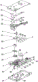
Fig. 1 is an exploded schematic view of an embodiment of the present invention.
Fig. 2 is the structure schematic diagram of the middle gear transmission pair, the shifting block and the rack plate after connection.
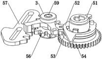
Fig. 3 is the exploded structure diagram of the middle gear transmission pair, the shifting block and the rack plate of the present invention.
Fig. 4 is another angle structure diagram of fig. 3.
Fig. 5 is the structure schematic diagram of the utility model after the cover plate is opened.
Fig. 6 is the structure schematic diagram of the utility model after the bottom shell is opened.
Detailed Description
The invention will be further described with reference to the following drawings and examples:
referring to fig. 1 to 6, a full-automatic electronic door lock, including the casing, spring bolt 4, control circuit and the motor drive assembly 6 that is used for driving spring bolt 4 to move, spring bolt 4 and motor drive assembly 6 set up in the casing, motor drive assembly 6 includes motor and reduction gear box, motor and control circuit electric connection, the outer end of spring bolt 4 stretches out outside the casing, the inner of spring bolt 4 is connected with arm-tie 41, still include the gear drive pair, drive toggle block 3, lock core 9 and rack plate 57 that arm-tie 41 moved, the motor passes through reduction gear box and is connected with gear drive pair transmission, gear drive pair respectively with toggle block 3 and rack plate 57 transmission connection, lock core 9 includes lock core shell, lock courage (not shown in the figure) and by cam 91 that the lock courage drove, cam 91 is connected with rack plate 57 transmission. A first guide groove 572 is formed in a surface of the rack plate 57, a guide pin is provided in the housing corresponding to the first guide groove 572, the guide pin is inserted into the first guide groove 572, and the first guide groove 572 and the guide pin are linearly slidably engaged with each other.
The gear transmission pair comprises a driving gear 54, a linkage gear 53 and a transmission gear 56, a positioning sleeve 55 is arranged on the shell, the driving gear 54 and the linkage gear 53 are sleeved on the positioning sleeve 55, the driving gear 54 is in transmission connection with the reduction gear box, a shifting lever is arranged on the driving gear 54, a first arc-shaped limiting groove 532 is arranged on the linkage gear 53 corresponding to the shifting lever, and the shifting lever extends into the first arc-shaped limiting groove 532; the transmission gear 56 is engaged with the linkage gear 53, the toggle block 3 comprises an axle center 35, a toggle arm 31 and a reset arm 34, the pulling plate 41 is provided with a long guide slot 42 corresponding to the axle center 35, the lower end of the axle center 35 penetrates through the long guide slot 42 to be connected with the center of the transmission gear 56, the toggle arm 31 and the reset arm 34 are respectively arranged on the periphery of the axle center 35, the toggle arm 31 is provided with a convex block 32, the pulling plate 41 is provided with a driving hole 43, the convex block 32 is inserted into the driving hole 43 and is in virtual fit with the driving hole 43, and the reset arm 34 is connected with the shell through.
The rack plate 57 is linearly arranged in the shell in a sliding mode, a rack is arranged on one side of the rack plate 57 and meshed with the transmission gear 56, and a contact block 571 is arranged on the other side of the rack plate 57 and is used for being in contact with the cam 91.
The scissors tongue 7 is arranged on the shell in a telescopic mode, one end of the scissors tongue 7 extends out of the shell, the backstop plate 71 is arranged in the shell in a rotating mode, the backstop plate 71 is used for blocking the scissors tongue 7 to move in a telescopic mode, the unlocking plate 52 is sleeved outside the positioning sleeve 55, a first unlocking arm 524 and a second unlocking arm 521 are arranged outside the unlocking plate 52, the first unlocking arm 524 is used for touching the backstop plate 71, the unlocking plate 58 is arranged in the shell in a linear sliding mode, one end (provided with a touch pin) of the unlocking plate 58 is used for touching the second unlocking arm 521, and the other end (unlocking touch end 581) of the unlocking plate 58 is in touch fit with the cam 91 of the lock cylinder 9.
The anti-return device further comprises an anti-return tongue 8 and an unlocking rod 81, wherein the anti-return tongue 8 is arranged on the shell in a telescopic mode, one end of the anti-return tongue 8 extends out of the shell, the other end of the anti-return tongue 8 abuts against one end of the unlocking rod 81, the unlocking rod 81 is arranged in the shell in a swinging mode, and the other end of the unlocking rod 81 abuts against the anti-return plate 71.
The number of the shift levers is two, the two shift levers are respectively a long shift lever 541 and a short shift lever 542, the unlocking piece 52 is provided with a second arc-shaped limiting groove 522 corresponding to the long shift lever 541, and the long shift lever 541 extends above the unlocking piece 52; the control circuit is provided with a motor reset detection switch 22 corresponding to the long driving lever 541.
The middle shaft 51 is inserted into the positioning sleeve 55 and is in rotating fit with the positioning sleeve 55, the linkage gear 53 is provided with a third arc-shaped limiting groove 533 corresponding to the limiting block 511, and the limiting block 511 extends into the third arc-shaped limiting groove 533; the unlocking piece 52 is provided with an unlocking pin 523 corresponding to the driving arm 512, and the driving arm 512 drives the unlocking piece 52 to rotate by touching the unlocking pin 523.
The center of the middle shaft 51 is provided with a transmission hole 513.
The bottom of the axis 35 of the toggle block 3 is provided with a clamping jaw 33, the shell is provided with a positioning shaft 59 corresponding to the transmission gear 56, the transmission gear 56 is rotatably arranged on the positioning shaft 59, the transmission gear 56 is provided with a clamping groove 561 corresponding to the clamping jaw 33, and the clamping jaw 33 is in inserted fit with the clamping groove 561.
The positioning sleeve 55 is fixedly connected with the shell.
The shell comprises a cover plate 11, a bottom shell 13 and a panel 12, and hole positions are respectively arranged on the panel 12 corresponding to the bolt 4, the scissors bolt 7 and the backstop bolt 8.
The control circuit comprises a circuit board 2, an upper cover 21 and a lower cover 25 are respectively arranged on the upper side and the lower side of the shell corresponding to the circuit board 2, and the circuit board 2 is packaged between the upper cover 21 and the lower cover 25. Motor reset detection switch 22 sets up on circuit board 2, still is equipped with spring bolt return detection switch 23 and spring bolt on circuit board 2 and stretches out detection switch 24, it is equipped with return touch head 45 and stretches out touch head 44 respectively to correspond spring bolt return detection switch 23 and spring bolt on arm-tie 41 and stretch out detection switch 24. In addition, a scissor tongue detection switch (not shown) and a retaining tongue detection switch 82 are provided in the housing.
The working principle is as follows: referring to fig. 5 and 6, the fully automatic electronic door lock is shown in an open state (i.e. a state when the door body is opened). Taking motor drive as an example: when the door is closed, the retaining tongue 8 retracts until the retaining tongue detection switch 82 is touched, meanwhile, the scissor tongue 7 extends out, the state of the scissor tongue detection switch is also changed, and a signal is sent to the circuit board 2, at the moment, the unlocking rod 81 also drives the retaining plate 71 to prevent the scissor tongue 7 from retracting, and the door body is locked through the scissor tongue 7; after waiting for a certain time, the circuit board 2 automatically controls the motor to rotate and start in the positive direction to drive the driving gear 54 to move, the driving gear 54 drives the linkage gear 53, the transmission gear 56, the rack plate 57 and the poking block 3 to move, the poking block 3 moves to drive the lock tongue 4 to extend out, and when the contact head 44 extending out of the pulling plate 41 is contacted with the lock tongue extension detection switch 24, the lock tongue is locked; finally, the circuit board 2 automatically controls the motor to rotate reversely to start, and drives the driving gear 54 to rotate by a certain angle until the long shift lever 541 touches the motor reset detection switch 22 (since the long shift lever 541 has a section of moving space in the first arc-shaped limiting groove 532, which is not in transmission with the linkage gear 53, the driving gear 54 does not drive the latch tongue 4 to retract in the process that the long shift lever 541 touches the motor reset detection switch 22, and the door closing and locking operations are completed.
In a door closing state: after the door opening instruction is input, the circuit board 2 controls the motor to rotate reversely until the first unlocking arm 524 driving the unlocking plate 52 triggers the anti-return plate 71 to unlock the scissor tongue 7 (the scissor tongue 7 is not blocked to retract), the latch bolt 4 retracts until the return contact head 45 touches the latch bolt return detection switch 23, at this moment, the user can open the door, and the full-automatic electronic door lock after the door is opened is restored to the state shown in fig. 5 and 6. If the door is closed, if the electric unlocking cannot be realized, the lock cylinder 9 can drive the cam 91 to rotate, the cam 91 rotates to trigger the contact block 571 of the rack plate 57, so as to drive the rack plate 57 to move linearly, the rack plate 57 drives the transmission gear 56, the toggle block 3 and the linkage gear 53 to move, the movement of the toggle block 3 drives the lock tongue 4 to retract, after the cam 91 rotates by a certain angle, the unlocking plate 58 can be triggered, the unlocking plate 58 drives the unlocking plate 52, the first unlocking arm 524 of the unlocking plate 52 triggers the retaining plate 71 to unlock the scissor tongue 7, and at this time, the user can open the door.
In addition, when the door is unlocked in the door, a user can drive the central shaft 51 to rotate through the handle, the limiting block 511 of the central shaft 51 drives the linkage gear 53, the transmission gear 56, the rack plate 57 and the toggle block 3 to move, the movement of the toggle block 3 drives the lock tongue 4 to retract, the driving arm 512 of the central shaft 51 drives the unlocking plate 52 to rotate through touching the unlocking pin 523, the first unlocking arm 524 of the unlocking plate 52 triggers the retaining plate 71 to unlock the scissor tongue 7, and at the moment, the user can open the door.
Claims (10)
1. A full-automatic electronic door lock comprises a shell, a bolt (4), a control circuit and a motor drive assembly (6) for driving the bolt (4) to move, wherein the bolt (4) and the motor drive assembly (6) are arranged in the shell, the motor drive assembly (6) comprises a motor and a reduction gear box, the motor is electrically connected with the control circuit, the outer end of the bolt (4) extends out of the shell, the inner end of the bolt (4) is connected with a pulling plate (41), it is characterized by also comprising a gear transmission pair, a shifting block (3) for driving the pulling plate (41) to move, a lock cylinder (9) and a rack plate (57), wherein the motor is in transmission connection with the gear transmission pair through a reduction gear box, the gear transmission pair is in transmission connection with the shifting block (3) and the rack plate (57) respectively, the lock core (9) comprises a lock core shell, a lock cylinder and a cam (91) driven by the lock cylinder, wherein the cam (91) is in transmission connection with the rack plate (57).
2. The full-automatic electronic door lock according to claim 1, wherein the gear transmission pair comprises a driving gear (54), a linkage gear (53) and a transmission gear (56), a positioning sleeve (55) is arranged on the housing, the driving gear (54) and the linkage gear (53) are sleeved on the positioning sleeve (55), the driving gear (54) is in transmission connection with the reduction gear box, a shifting lever is arranged on the driving gear (54), a first arc-shaped limiting groove (532) is arranged on the linkage gear (53) corresponding to the shifting lever, and the shifting lever extends into the first arc-shaped limiting groove (532); the transmission gear (56) is meshed with the linkage gear (53), the shifting block (3) comprises an axle center (35), a shifting arm (31) and a reset arm (34), the pulling plate (41) is provided with a long guide groove (42) corresponding to the axle center (35), the lower end of the axle center (35) penetrates through the long guide groove (42) to be connected with the center of the transmission gear (56), the shifting arm (31) and the reset arm (34) are respectively arranged on the periphery of the axle center (35), the shifting arm (31) is provided with a convex block (32), the pulling plate (41) is provided with a driving hole (43), the convex block (32) is inserted into the driving hole (43) and is in virtual position fit with the driving hole (43), and the reset arm (34) is connected with the shell through a torsion.
3. The full-automatic electronic door lock according to claim 2, wherein the rack plate (57) is linearly slidably disposed in the housing, a rack is disposed on one side of the rack plate (57) and engaged with the transmission gear (56), and a contact block (571) is disposed on the other side of the rack plate (57), and the contact block (571) is used for contacting with the cam (91).
4. The full-automatic electronic door lock is characterized by further comprising a shear tongue (7), a backstop plate (71), an unlocking sheet (52) and an unlocking plate (58), wherein the shear tongue (7) is arranged on the shell in a telescopic mode, one end of the shear tongue (7) extends out of the shell, the backstop plate (71) is arranged in the shell in a rotating mode, the backstop plate (71) is used for blocking the telescopic motion of the shear tongue (7), the unlocking sheet (52) is sleeved outside the positioning sleeve (55), a first unlocking arm (524) and a second unlocking arm (521) are arranged outside the unlocking sheet (52), the first unlocking arm (524) is used for triggering the backstop plate (71), the unlocking sheet (58) is arranged in the shell in a linear sliding mode, one end of the unlocking sheet (58) is used for triggering the second unlocking arm (521), and the other end of the unlocking sheet (58) is in triggering fit with a cam (91) of the lock cylinder (9).
5. The full-automatic electronic door lock according to claim 4, characterized by further comprising a retaining tongue (8) and an unlocking rod (81), wherein the retaining tongue (8) is telescopically arranged on the housing, one end of the retaining tongue (8) extends out of the housing, the other end of the retaining tongue (8) abuts against one end of the unlocking rod (81), the unlocking rod (81) is arranged in the housing in a swinging manner, and the other end of the unlocking rod (81) abuts against the retaining plate (71).
6. The fully automatic electronic door lock according to claim 4, wherein there are two shift levers, the two shift levers are a long shift lever (541) and a short shift lever (542), the unlocking plate (52) is provided with a second arc-shaped limiting groove (522) corresponding to the long shift lever (541), and the long shift lever (541) extends above the unlocking plate (52); the control circuit is provided with a motor reset detection switch (22) corresponding to the long deflector rod (541).
7. The full-automatic electronic door lock according to claim 4, further comprising a middle shaft (51), wherein a limit block (511) and a driving arm (512) are arranged on the periphery of the middle shaft (51), the middle shaft (51) is inserted into the positioning sleeve (55) and is in rotating fit with the positioning sleeve (55), the linkage gear (53) is provided with a third arc-shaped limit groove (533) corresponding to the limit block (511), and the limit block (511) extends into the third arc-shaped limit groove (533); the unlocking piece (52) is provided with an unlocking pin (523) corresponding to the driving arm (512), and the driving arm (512) drives the unlocking piece (52) to rotate by touching the unlocking pin (523).
8. The fully automatic electronic door lock according to claim 7, characterized in that the centre shaft (51) is provided with a drive hole (513) in its centre.
9. The full-automatic electronic door lock according to claim 2, wherein a clamping jaw (33) is arranged at the bottom of the shaft center (35) of the toggle block (3), the housing is provided with a positioning shaft (59) corresponding to the transmission gear (56), the transmission gear (56) is rotatably arranged on the positioning shaft (59), the transmission gear (56) is provided with a clamping groove (561) corresponding to the clamping jaw (33), and the clamping jaw (33) is in inserted fit with the clamping groove (561).
10. The fully automatic electronic door lock according to claim 2, characterized in that the positioning sleeve (55) is fixedly connected with the housing.
Priority Applications (1)
| Application Number | Priority Date | Filing Date | Title |
|---|---|---|---|
| CN201922223761.4U CN211258118U (en) | 2019-12-12 | 2019-12-12 | Full-automatic electronic door lock |
Applications Claiming Priority (1)
| Application Number | Priority Date | Filing Date | Title |
|---|---|---|---|
| CN201922223761.4U CN211258118U (en) | 2019-12-12 | 2019-12-12 | Full-automatic electronic door lock |
Publications (1)
| Publication Number | Publication Date |
|---|---|
| CN211258118U true CN211258118U (en) | 2020-08-14 |
Family
ID=71988766
Family Applications (1)
| Application Number | Title | Priority Date | Filing Date |
|---|---|---|---|
| CN201922223761.4U Active CN211258118U (en) | 2019-12-12 | 2019-12-12 | Full-automatic electronic door lock |
Country Status (1)
| Country | Link |
|---|---|
| CN (1) | CN211258118U (en) |
Cited By (1)
| Publication number | Priority date | Publication date | Assignee | Title |
|---|---|---|---|---|
| CN110965859A (en) * | 2019-12-12 | 2020-04-07 | 中山市皇鼎五金制品有限公司 | Full-automatic electronic door lock |
-
2019
- 2019-12-12 CN CN201922223761.4U patent/CN211258118U/en active Active
Cited By (1)
| Publication number | Priority date | Publication date | Assignee | Title |
|---|---|---|---|---|
| CN110965859A (en) * | 2019-12-12 | 2020-04-07 | 中山市皇鼎五金制品有限公司 | Full-automatic electronic door lock |
Similar Documents
| Publication | Publication Date | Title |
|---|---|---|
| CN110965859A (en) | Full-automatic electronic door lock | |
| CN108756471B (en) | High-strength safe intelligent lock cylinder | |
| CN212336961U (en) | Locking and unlocking mechanism of lock tongue and full-automatic lock with same | |
| CN211258118U (en) | Full-automatic electronic door lock | |
| CN108005491A (en) | The linkage interlocked handle clutch of intelligent gun (bullet) cabinet | |
| CN111608494A (en) | Full-automatic safety lock body | |
| CN111485767A (en) | Electronic cabinet lock | |
| CN109577750B (en) | Electronic lock | |
| CN211258119U (en) | Unlocking transmission structure of full-automatic electronic door lock | |
| CN213477908U (en) | Clutch control device of electromechanical lock | |
| CN114427325B (en) | Full-automatic heavy electronic door lock | |
| CN209704217U (en) | A kind of Electric lock | |
| CN217361476U (en) | Locking and unlocking structure of plug-in circuit breaker | |
| CN111173384B (en) | Hasp type cabin lock | |
| CN212583442U (en) | Lock body capable of being opened and closed quickly | |
| CN212271848U (en) | Full-automatic safety lock body | |
| CN105442956B (en) | A kind of safety door latch | |
| CN212105490U (en) | Hasp type cabin lock | |
| CN110185318B (en) | Door lock with clutch shifting fork device | |
| CN110616966B (en) | Electric lock body | |
| CN212837191U (en) | Motor lock | |
| CN110593647B (en) | Tipping bucket tongue device and full-automatic lock system comprising same | |
| CN210067701U (en) | Intelligent lock capable of automatically locking and unlocking and reversely reversing lock tongue | |
| CN210289395U (en) | Clutch fork device of door lock | |
| CN219711239U (en) | Escape double-quick lock body for intelligent lock |
Legal Events
| Date | Code | Title | Description |
|---|---|---|---|
| GR01 | Patent grant | ||
| GR01 | Patent grant |