CN211248902U - Bridge plate welding anti-deformation device - Google Patents
Bridge plate welding anti-deformation device Download PDFInfo
- Publication number
- CN211248902U CN211248902U CN201922447519.5U CN201922447519U CN211248902U CN 211248902 U CN211248902 U CN 211248902U CN 201922447519 U CN201922447519 U CN 201922447519U CN 211248902 U CN211248902 U CN 211248902U
- Authority
- CN
- China
- Prior art keywords
- hydraulic cylinder
- roll
- over stand
- over
- pressing
- Prior art date
- Legal status (The legal status is an assumption and is not a legal conclusion. Google has not performed a legal analysis and makes no representation as to the accuracy of the status listed.)
- Active
Links
Images


Landscapes
- Butt Welding And Welding Of Specific Article (AREA)
Abstract
The utility model relates to a anti-deformation device especially relates to a bridge plate welding anti-deformation device. The lower end of the roll-over stand is provided with a supporting leg for supporting and fixing the roll-over stand, the left side of the supporting leg is provided with a roll-over assembly for turning the roll-over stand left and right, and the roll-over assembly comprises a base, a first hydraulic cylinder and a second hydraulic cylinder, wherein the first hydraulic cylinder and the second hydraulic cylinder are arranged on the base, and the other end of the first hydraulic cylinder is hinged with the; the anti-deformation mechanism comprises a plurality of boxes which are uniformly arranged on the roll-over stand at intervals, arc plates which are arranged on two sides of the boxes and used for limiting the bridge plates, a first pressing part and a second pressing part which are movably arranged in the boxes and used for fixedly pressing the bridge plates, and a third hydraulic cylinder which is horizontally arranged at the lower end of the roll-over part and used for adjusting the distance between the first pressing part and the second pressing part, wherein the first hydraulic cylinder, the second hydraulic cylinder and the third hydraulic cylinder are connected with a hydraulic main station pipeline. The utility model discloses simple operation, anti-deformation effect are good.
Description
Technical Field
The utility model relates to a anti-deformation device especially relates to a bridge plate welding anti-deformation device.
Background
Welding is the process of joining metal parts using various fusible alloys (solders). The melting point of the solder is lower than that of the material to be welded, so that the welding is completed by intermolecular connection between the surfaces of the parts without melting the parts. During soldering, molten solder flows between the two metal parts, and under favourable conditions a strong, tight, corrosion-resistant and electrically and thermally conductive connection is obtained between the solder and the metal.
The non-uniform temperature field of the welding process and the local plastic deformation and the structure of different specific volumes caused by it are the root causes of the generation of welding stresses and deformations. When the non-uniform temperature field caused by welding has not disappeared, such stresses and deformations in the weldment are called transient weld stresses and deformations; the stress and distortion after the weld temperature field disappears are referred to as residual weld stress and distortion. In the absence of external forces, the welding stresses are balanced within the weldment. Weld stress and distortion can affect the function and appearance of the weldment under certain conditions and is therefore a matter of design and manufacturing that must be considered. The magnitude of the weld distortion is related to the size, number and arrangement of the welds. First, the number of welds, the shape and the size of the groove are determined reasonably from the design, and the position of the welds is arranged properly, which is important for reducing the deformation. In order to reduce welding deformation, reasonable assembly, reversible deformation and rigid fixation are required.
SUMMERY OF THE UTILITY MODEL
An object of the utility model is to overcome not enough among the prior art, and provide a bridge plate welding anti-deformation device, the utility model discloses the simple operation, anti-deformation effect are good.
In order to realize the above purpose, the utility model discloses a technical scheme is: the bridge plate welding reversible deformation device comprises a roll-over stand and a hydraulic main station, wherein a supporting leg for supporting and fixing the roll-over stand is arranged at the lower end of the roll-over stand, a roll-over assembly for turning the roll-over stand left and right is arranged on the left side of the supporting leg, and the roll-over assembly comprises a base, a first hydraulic cylinder and a second hydraulic cylinder, wherein the first hydraulic cylinder and the second hydraulic cylinder are arranged on the base, and the other end of the first hydraulic cylinder is;
the anti-deformation mechanism comprises a plurality of boxes which are uniformly arranged on the roll-over stand at intervals, arc plates which are arranged on two sides of the boxes and used for limiting the bridge plates, a first pressing part and a second pressing part which are movably arranged in the boxes and used for fixedly pressing the bridge plates, and a third hydraulic cylinder which is horizontally arranged at the lower end of the roll-over part and used for adjusting the distance between the first pressing part and the second pressing part, wherein the first hydraulic cylinder, the second hydraulic cylinder and the third hydraulic cylinder are connected with a hydraulic main station pipeline.
In order to further realize the utility model discloses, can prefer following technical scheme for use:
preferably, the lower end of the roll-over stand is hinged to the support leg, a stroke limiting plate is arranged at the hinged position of the support leg and the roll-over stand, and the roll-over angle of the roll-over stand is 0-35 degrees under the action of the stroke limiting plate.
Preferably, the first pressing piece and the second pressing piece both comprise a support matched with the box body, rollers arranged on the left side and the right side of the support and used for guiding, a long shaft arranged in the support and extending from the upper part of the long shaft to the outer side of the box body, a pressing block arranged at the upper end of the long shaft and used for pressing the bridge plate, and a fourth hydraulic cylinder arranged at the lower end of the long shaft and used for enabling the long shaft to move up and down, and the fourth hydraulic cylinder is connected with a hydraulic main station pipeline.
Preferably, the box is close to evenly to be provided with the locating hole on the both sides wall that compresses tightly one end, compress tightly and be provided with the position control board on one's the support, the position control board both sides all are provided with locating pin of locating hole assorted, compress tightly one and adjust the position on the box through the position control board.
Preferably, the bracket of the second pressing piece is connected with the driving end of the hydraulic cylinder III, and the position of the second pressing piece on the box body is adjusted through the hydraulic cylinder III.
Preferably, the upper part of the roll-over stand is provided with a support frame for supporting the bridge plate, and the support frame is perpendicular to the arc-shaped plate.
The utility model has the advantages that: the utility model discloses in be provided with the landing leg, articulated on the landing leg have the roll-over stand, be provided with anti-deformation mechanism on the roll-over stand, anti-deformation mechanism includes a plurality of boxes of even interval setting on the roll-over stand, set up in the box left and right sides and be used for carrying on spacing arc to the bridge plate, the activity sets up in the box and is used for the fixed clamp down one and the clamp down two that compress down the bridge plate, the level sets up at the lower extreme of roll-over and is used for adjusting the pneumatic cylinder three that compresses down one and clamp down the interval between two, clamp down one and clamp down two pairs of bridge plates, make bridge plate and arc laminating form the arch, form anti-deformation power, can effectually reduce the bridge plate and produce the deformation in the welding; the turnover frame can effectively reach the angle required by the bridge plate welding technology under the action of the first hydraulic cylinder and the second hydraulic cylinder, and the structure is convenient to operate and good in anti-deformation effect.
Drawings
Fig. 1 is a schematic structural diagram of embodiment 1 of the present invention;
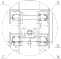
fig. 2 is a plan view of embodiment 1 of the present invention;
fig. 3 is a left side view of embodiment 1 of the present invention;
FIG. 4 is an enlarged view of part A of the present invention;
FIG. 5 is an enlarged view of the portion B of the present invention;
wherein: 1-supporting leg, 2-turning frame, 3-box body, 4-first pressing piece, 5-second pressing piece, 6-arc-shaped plate, 7-base, 8-first hydraulic cylinder, 9-second hydraulic cylinder, 10-stroke limiting plate, 11-support, 12-roller, 13-fourth hydraulic cylinder, 14-long shaft, 15-pressing block, 16-position adjusting plate, 17-positioning hole, 18-supporting frame, 19-third hydraulic cylinder and 20-hydraulic general table.
Detailed Description
In the description of the present invention, it should also be noted that, unless otherwise explicitly specified or limited, the terms "disposed," "mounted," "connected," and "connected" are to be construed broadly, e.g., as meaning either a fixed connection, a removable connection, or an integral connection; can be mechanically or electrically connected; they may be connected directly or indirectly through intervening media, or they may be interconnected between two elements. The specific meaning of the above terms in the present invention can be understood in specific cases to those skilled in the art.
The technical solutions in the embodiments of the present invention will be described clearly and completely with reference to the accompanying drawings in the embodiments of the present invention, and it is obvious that the described embodiments are only some embodiments of the present invention, not all embodiments. Based on the embodiments in the present invention, all other embodiments obtained by a person skilled in the art without creative work belong to the protection scope of the present invention.
Example 1:
1-5, the bridge plate welding reversible deformation device comprises a support leg 1, wherein the upper end of the support leg is hinged with a roll-over stand 2, the lower end of the roll-over stand is provided with a roll-over assembly for left and right roll-over of the roll-over stand, the roll-over assembly comprises a base 7, a first hydraulic cylinder 8 and a second hydraulic cylinder 9, the first hydraulic cylinder 8 and the second hydraulic cylinder are hinged to the left and right sides of the base, the left end of the first hydraulic cylinder 8 is hinged to the lower portion of; the right end of the hydraulic cylinder II 9 is hinged with the lower part of the right side of the roll-over stand, and the left end of the hydraulic cylinder II is hinged with the base; the hinge joint of the support leg 1 and the roll-over stand is provided with a stroke limiting plate 10 for limiting the roll-over angle of the roll-over stand, when the bridge plate is fixed on the roll-over stand, the bridge plate and the roll-over stand are driven by a hydraulic cylinder I and a hydraulic cylinder II to realize left-right roll-over, the maximum roll-over angle is 30 degrees, the angle of the bridge plate welding technical requirement can be effectively reached, and the bridge plate is matched with subsequent welding, so that the use is convenient;
the anti-deformation mechanism is arranged on the roll-over stand 2 and used for reducing deformation of the welded bridge plate, and comprises a plurality of boxes 3 which are uniformly arranged on the roll-over stand at intervals, arc plates 6 which are arranged on two sides of the boxes and have the same length with the boxes, a first pressing part 4 and a second pressing part 5 which are movably arranged in the boxes and are used for fixing the bridge plate, and a third hydraulic cylinder 19 which is horizontally arranged at the lower part of the roll-over part and is used for adjusting the distance between the first pressing part and the second pressing part, wherein the first hydraulic cylinder 8, the second hydraulic cylinder 9 and the third hydraulic cylinder 19 are connected with a hydraulic; the first pressing piece and the second pressing piece both comprise a support 11 matched with the inside of the box body, rollers 12 which are arranged on the left side and the right side of the support and used for guiding, a long shaft 14 which is arranged in the support and the upper part of which extends to the outside of the box body, a pressing block 15 which is arranged at the upper end of the long shaft and used for pressing the bridge plate, and a fourth hydraulic cylinder 13 which is arranged at the lower end of the long shaft and used for driving the long shaft to move up and down, wherein the fourth hydraulic cylinder 13; positioning holes 17 are uniformly formed in two side walls of one end, close to the pressing part, of the box body, a position adjusting plate 16 is installed on a support of the pressing part I, a through hole is formed in the position adjusting plate, a positioning pin penetrates through the through hole and is inserted into the positioning holes 17, the position of the pressing part I on the box body is adjusted through manually adjusting the position adjusting plate, the support of the pressing part II is connected with the driving end of the hydraulic cylinder III 19, and the position of the pressing part II on the box body is adjusted through the hydraulic cylinder III;
the supporting frame 18 is vertically arranged on the upper portion of the turnover frame and the arc-shaped plate, the pressing block of the first pressing piece moves downwards under the action of the first pressing piece hydraulic cylinder IV to clamp the bridge plate, the pressing block of the second pressing piece moves downwards under the action of the second pressing piece hydraulic cylinder IV to clamp the bridge plate, the clamped bridge plate is attached to the arc-shaped plate, the bridge plate is arched to form anti-deformation force, deformation of the bridge plate in the welding process can be effectively reduced, the structural design is reasonable, and the anti-deformation effect is good.
The working process of the embodiment is as follows:
when the roll-over stand is horizontally placed, the position of a first pressing piece is manually adjusted, a positioning pin of the first pressing piece is inserted into a positioning hole after adjustment, the bridge plate is placed on the roll-over stand by using external hoisting equipment, a second pressing piece moves to a proper position under the action of a third hydraulic cylinder, a long shaft of the first pressing piece moves downwards under the action of a fourth hydraulic cylinder of the first pressing piece, a first pressing block of a component is further driven to press a lower pressing plate bridge, a long shaft of the second pressing piece moves downwards under the action of a fourth hydraulic cylinder of the second pressing piece, the pressing block of the second pressing piece is further driven to press the other end of the plate bridge downwards, and the position of the first pressing piece is adjusted at any time under the action of the third hydraulic cylinder in the pressing process until the bridge plate is attached to the arc-shaped plate; the fixed bridge plate forms an arch under the action of the arc plate to form anti-deformation force, welding deformation of the plate bridge is reduced, and the turnover frame is turned over under the first hydraulic cylinder and the second hydraulic cylinder by 0-30 degrees so as to meet the angle requirement of the plate bridge welding technology.
Finally, it should be noted that: although the present invention has been described in detail with reference to the foregoing embodiments, it will be apparent to those skilled in the art that modifications and variations can be made in the embodiments or in part of the technical features of the embodiments without departing from the spirit and the scope of the invention.
Claims (6)
1. The utility model provides a bridge plate welding anti-deformation device, includes roll-over stand and hydraulic pressure total station, its characterized in that: the lower end of the roll-over stand is provided with a supporting leg for supporting and fixing the roll-over stand, the left side of the supporting leg is provided with a roll-over assembly for turning the roll-over stand left and right, and the roll-over assembly comprises a base, a first hydraulic cylinder and a second hydraulic cylinder, wherein the first hydraulic cylinder and the second hydraulic cylinder are arranged on the base, and the other end of the first hydraulic cylinder is hinged with the;
the anti-deformation mechanism comprises a plurality of boxes which are uniformly arranged on the roll-over stand at intervals, arc plates which are arranged on two sides of the boxes and used for limiting the bridge plates, a first pressing part and a second pressing part which are movably arranged in the boxes and used for fixedly pressing the bridge plates, and a third hydraulic cylinder which is horizontally arranged at the lower end of the roll-over part and used for adjusting the distance between the first pressing part and the second pressing part, wherein the first hydraulic cylinder, the second hydraulic cylinder and the third hydraulic cylinder are connected with a hydraulic main station pipeline.
2. The bridge plate welding predeformation device of claim 1, wherein: the lower end of the roll-over stand is hinged to the supporting leg, a stroke limiting plate is arranged at the hinged position of the supporting leg and the roll-over stand, and the roll-over angle of the roll-over stand is 0-35 degrees under the action of the stroke limiting plate.
3. The bridge plate welding predeformation device of claim 1, wherein: the first pressing piece and the second pressing piece both comprise a support matched with the box body, rollers arranged on the left side and the right side of the support and used for guiding, a long shaft arranged in the support and extending from the upper portion of the long shaft to the outer side of the box body, a pressing block arranged at the upper end of the long shaft and used for pressing the bridge plate, and a fourth hydraulic cylinder arranged at the lower end of the long shaft and used for enabling the long shaft to move up and down, wherein the fourth hydraulic cylinder is connected with a hydraulic main platform pipeline.
4. The bridge plate welding predeformation device of claim 3, wherein: evenly be provided with the locating hole on the both sides wall that the box is close to one end that compresses tightly, compress tightly and be provided with the position control board on one's the support, position control board both sides all are provided with locating pin of locating hole assorted, compress tightly one and adjust the position on the box through the position control board.
5. The bridge plate welding predeformation device of claim 3, wherein: the bracket of the second pressing piece is connected with the driving end of the third hydraulic cylinder, and the position of the second pressing piece on the box body is adjusted through the third hydraulic cylinder.
6. The bridge plate welding predeformation device of claim 1, wherein: the upper part of the roll-over stand is provided with a support frame for supporting the bridge plate, and the support frame is perpendicular to the arc-shaped plate.
Priority Applications (1)
| Application Number | Priority Date | Filing Date | Title |
|---|---|---|---|
| CN201922447519.5U CN211248902U (en) | 2019-12-30 | 2019-12-30 | Bridge plate welding anti-deformation device |
Applications Claiming Priority (1)
| Application Number | Priority Date | Filing Date | Title |
|---|---|---|---|
| CN201922447519.5U CN211248902U (en) | 2019-12-30 | 2019-12-30 | Bridge plate welding anti-deformation device |
Publications (1)
| Publication Number | Publication Date |
|---|---|
| CN211248902U true CN211248902U (en) | 2020-08-14 |
Family
ID=71981159
Family Applications (1)
| Application Number | Title | Priority Date | Filing Date |
|---|---|---|---|
| CN201922447519.5U Active CN211248902U (en) | 2019-12-30 | 2019-12-30 | Bridge plate welding anti-deformation device |
Country Status (1)
| Country | Link |
|---|---|
| CN (1) | CN211248902U (en) |
-
2019
- 2019-12-30 CN CN201922447519.5U patent/CN211248902U/en active Active
Similar Documents
| Publication | Publication Date | Title |
|---|---|---|
| CN100581702C (en) | Welding for large scale abutting joint connection sectional material | |
| CN105935843B (en) | A kind of structural member welding method | |
| CN207824302U (en) | A kind of auxiliary welding equipment of circuit board | |
| CN211248902U (en) | Bridge plate welding anti-deformation device | |
| CN101468430B (en) | Novel laser welding and assembling clamp for GIS controlling cabinet | |
| CN104526123B (en) | Passenger vehicle back wall assembly assembling-welding fixtures and use it to carry out the technique of back wall assembly welding equipment | |
| CN208374584U (en) | Flange welding Deformation control equipment | |
| CN211248939U (en) | Welding tool for front and back assembly of car roof | |
| CN205147572U (en) | Power battery module utmost point ear welding tool equipment | |
| CN210147214U (en) | Straight seam welding machine for T-shaped workpiece | |
| CN205021069U (en) | Positioner | |
| CN113878280B (en) | Welding deformation preventing device for large megawatt rotor cone | |
| CN107790940A (en) | A kind of stainless-steel sheet welding splicing body | |
| CN203282100U (en) | Press-cake-row type pressing deice used for steel plate butt joint closing machining | |
| CN212070782U (en) | Dual-purpose laser welding equipment of handheld welder of robot | |
| CN213497442U (en) | Automatic welding fixture for side door of railway open wagon | |
| CN107999984A (en) | A kind of welding method for discharging thermal energy Reducing distortion | |
| CN208961197U (en) | Prevent the welder of steam head plate welding deformation | |
| CN208408964U (en) | A kind of automatic soldering device | |
| CN209773826U (en) | Arc welding fixture and arc welding deformation correcting mechanism | |
| CN207942125U (en) | A kind of deadlock anti-deformation arc welding fixture | |
| CN211991485U (en) | Device for welding inclined support piece | |
| CN217493156U (en) | Tower standard section welding tool platform | |
| CN212599894U (en) | Quick welding jig structure for machine case component | |
| CN210840264U (en) | Circuit board electronic component assembling frame |
Legal Events
| Date | Code | Title | Description |
|---|---|---|---|
| GR01 | Patent grant | ||
| GR01 | Patent grant |