CN211176554U - Multifunctional L ED wall lamp - Google Patents
Multifunctional L ED wall lamp Download PDFInfo
- Publication number
- CN211176554U CN211176554U CN201922037677.3U CN201922037677U CN211176554U CN 211176554 U CN211176554 U CN 211176554U CN 201922037677 U CN201922037677 U CN 201922037677U CN 211176554 U CN211176554 U CN 211176554U
- Authority
- CN
- China
- Prior art keywords
- connecting strip
- line connecting
- slider
- fixed
- spout
- Prior art date
- Legal status (The legal status is an assumption and is not a legal conclusion. Google has not performed a legal analysis and makes no representation as to the accuracy of the status listed.)
- Expired - Fee Related
Links
Images


Abstract
The utility model discloses a multi-functional L ED wall lamp belongs to lamps and lanterns technical field, which comprises a fixing plate and i, the spout has been seted up to the inside of fixed plate, and the inside of spout is provided with the slider, be provided with fixed establishment between spout and the slider, the bilateral symmetry that the slider is close to the fixed plate is provided with first line connecting strip, and the inboard symmetry of spout be provided with first line connecting strip matched with second line connecting strip, first line connecting strip and the laminating of second line connecting strip, fixed mounting has the mounting panel on the slider, the utility model discloses a slider on the fixed plate is used with the slider cooperation on the mounting panel for the device can be dismantled at the in-process that uses, and utilizes the inside battery of mounting panel, adopts the battery to supply power for L ED lamp, makes the device can dismantle exclusive use, conveniently throws light on the open air, has improved the functionality of device.
Description
Technical Field
The utility model relates to a wall lamp especially relates to a multi-functional L ED wall lamp, belongs to lamps and lanterns technical field.
Background
Wall lamp is the auxiliary lighting device lamps and lanterns of installing on indoor wall, generally the polygamy lamp shade, and light is elegant harmonious, can be the environment decorated graceful, rich, is particularly suitable for in the wedding room, consequently by extensive use, but current wall lamp is at the in-process that uses, and the function is comparatively single, and adopts fixed mounting's mode, can't adjust and dismantle the use, and the pattern of lamp shade is fixed in addition, and the practicality is lower, consequently, the utility model provides a problem that exists among the multi-functional L ED wall lamp in order to solve prior art.
SUMMERY OF THE UTILITY MODEL
The utility model mainly aims at providing a multi-functional L ED wall lamp to can't carry out position control and dismantlement among the solution prior art, and the fixed problem of lamp shade pattern.
The purpose of the utility model can be achieved by adopting the following technical scheme:
the utility model provides a multi-functional L ED wall lamp, includes the fixed plate, the spout has been seted up to the inside of fixed plate, and the inside of spout is provided with the slider, be provided with fixed establishment between spout and the slider, the bilateral symmetry that the slider is close to the fixed plate is provided with first line connecting strip, and the inboard symmetry of spout is provided with first line connecting strip matched with second line connecting strip, first line connecting strip and the laminating of second line connecting strip, fixed mounting has the mounting panel on the slider, and the inside of mounting panel is fixed with the battery, the outside of mounting panel is provided with the lamp shade, and the inside of lamp shade is provided with L ED lamp, first line connecting strip passes through wire and battery intercommunication, and the battery passes through wire and L ED lamp intercommunication.
Preferably: the bilateral symmetry of lamp shade is provided with a storage cylinder, and the internally mounted of storage cylinder has the bull stick, the outside of bull stick all twines lamp shade plastic film, and is two sets of the inside lamp shade plastic film of storage cylinder covers the outside and the fixed connection of lamp shade, the top of bull stick extends to the outside of storage cylinder, and the top of bull stick is fixed with adjust knob.
Preferably: the fixing mechanism comprises a mounting groove, a clamping block and a clamping groove, the mounting groove is located inside the sliding block, the opening of the mounting groove faces the fixing plate, a pressure spring is fixed inside the mounting groove and faces the opening of the mounting groove, the clamping block is fixed to one end, open, of the mounting groove, and the clamping groove matched with the clamping block is evenly formed in the inner side of the sliding groove.
Preferably: the lampshade plastic film comprises a smooth surface, a frosted surface and a striped surface, the frosted surface is arranged on one side of the smooth surface, the striped surface is arranged on one side, away from the smooth surface, of the frosted surface, and a graphic surface is arranged on one side, away from the frosted surface, of the striped surface.
Preferably: the shape of the clamping block is a right triangle, and the inclined plane of the clamping block faces to one side far away from the storage battery.
Preferably: the outside of first line connecting strip is provided with the elasticity fin.
The utility model has the advantages that:
the utility model provides a pair of multi-functional L ED wall lamp, slider cooperation through on the fixed plate and the mounting panel is used, make the device can dismantle at the in-process that uses, and utilize the inside battery of mounting panel, adopt the battery to supply power for L ED lamp, make the device can dismantle the exclusive use, conveniently throw light on in the open air, the functionality of device has been improved, the setting of lamp shade plastic film between the storage section of thick bamboo is inside, through the change of multiple face on the lamp shade plastic film, can adjust the pattern and the luminance of light, the functionality and the practicality of device have been improved.
Drawings
FIG. 1 is a three-dimensional structure of the present invention;
fig. 2 is a sectional view of the fixing plate of the present invention;
fig. 3 is a schematic view of the inside of the storage tank of the present invention;
fig. 4 is a schematic view of the fixing mechanism of the present invention;
fig. 5 is a schematic view of the plastic film of the lampshade of the present invention.
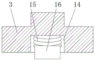
In the figure: 1-fixing plate, 2-sliding chute, 3-sliding block, 4-fixing mechanism, 5-first line connecting strip, 6-second line connecting strip, 7-mounting plate, 8-storage battery, 9-lampshade, 10-storage cylinder, 11-rotating rod, 12-lampshade plastic film, 13-adjusting knob, 14-mounting groove, 15-pressure spring, 16-clamping block, 17-clamping groove, 18-smooth surface, 19-frosting surface, 20-striped surface and 21-pattern surface.
Detailed Description
In order to make the technical solutions of the present invention clearer and clearer for those skilled in the art, the present invention will be described in further detail with reference to the following embodiments and drawings, but the embodiments of the present invention are not limited thereto.
As shown in fig. 1-5, this embodiment provides a multi-functional L ED wall lamp, including fixed plate 1, spout 2 has been seted up to fixed plate 1's inside, and spout 2's inside is provided with slider 3, be provided with fixing mechanism 4 between spout 2 and the slider 3, slider 3 is provided with first line connecting strip 5 near fixed plate 1's bilateral symmetry, and spout 2's inboard symmetry is provided with the second line connecting strip 6 with first line connecting strip 5 matched with, first line connecting strip 5 and the laminating of second line connecting strip 6, fixed mounting has mounting panel 7 on the slider 3, and the inside of mounting panel 7 is fixed with battery 8, the outside of mounting panel 7 is provided with lamp shade 9, and the inside of lamp shade 9 is provided with L ED lamp, first line connecting strip 5 passes through wire and battery 8 intercommunication, and battery 8 passes through wire and L ED lamp intercommunication.
In this embodiment, as shown in fig. 1, storage cylinders 10 are symmetrically arranged on two sides of a lampshade 9, a rotating rod 11 is installed inside each storage cylinder 10, lampshade plastic films 12 are wound on the outer sides of the rotating rods 11, the lampshade plastic films 12 inside two groups of storage cylinders 10 cover the outer sides of the lampshade 9 and are fixedly connected, the top of each rotating rod 11 extends to the outer side of each storage cylinder 10, an adjusting knob 13 is fixed on the top of each rotating rod 11, one group of rotating rods 11 is rotated to shrink the lampshade plastic films 12, the positions of the lampshade plastic films 12 are changed, and light is adjusted.
In this embodiment, as shown in fig. 1, fixing mechanism 4 includes mounting groove 14, fixture block 16 and draw-in groove 17, mounting groove 14 is located the inside of slider 3, and the opening of mounting groove 14 is towards fixed plate 1, the inside of mounting groove 14 is fixed with pressure spring 15, and pressure spring 15 is fixed with fixture block 16 towards the one end of 14 openings of mounting groove, draw-in groove 17 with fixture block 16 matched with has evenly been seted up to the inboard of spout 2, when slider 3 upwards slides under the inside of spout 2, because when in-process fixture block 16 slides on the horizontal plane of draw-in groove 17, pressure spring 15 promotes the inside that fixture block 16 stretched into fixture block 17 and fixes the device, change the position of lamp shade 9 then.
In the embodiment, as shown in fig. 1, the lampshade plastic film 12 comprises a smooth surface 18, a frosted surface 19 and a striped surface 20, wherein one side of the smooth surface 18 is provided with the frosted surface 19, one side of the frosted surface 19 far away from the smooth surface 18 is provided with the striped surface 20, one side of the striped surface 20 far away from the frosted surface 19 is provided with a pattern surface 21, and the pattern of the light and the brightness of the light are adjusted by changing the positions of the smooth surface 18, the frosted surface 19, the striped surface 20 and the pattern surface 21.
In the present embodiment, as shown in fig. 1, the shape of the latch 16 is a right triangle, and the inclined surface of the latch 16 faces the side away from the battery 8, so that the device is convenient to mount and is firmly fixed.
In this embodiment, as shown in fig. 1, the outside of first line connecting strip 5 is provided with the elasticity fin, ensures that first connecting strip 5 and second connecting strip 6 can laminate in the use, has improved the stability of connecting.
As shown in fig. 1 to 5, the present embodiment provides a multifunctional L ED wall lamp, which works as follows:
step 2: in the use process of the wall lamp, the position of a plastic film 12 of a lampshade is changed by rotating a rotating rod 11, and a smooth surface 18, a frosted surface 19, a striped surface 20 and a pattern surface 21 are converted on the outer side of the lampshade, so that the brightness of lamplight and a mapped pattern are changed;
and 3, pulling the sliding block 3 out of the chute 2 when going out, and directly supplying power to the L ED lamp by the storage battery 8 for illumination.
The above description is only a further embodiment of the present invention, but the scope of protection of the present invention is not limited thereto, and any person skilled in the art can replace or change the technical solution and the concept of the present invention within the scope of the present invention.
Claims (6)
1. The utility model provides a multi-functional L ED wall lamp, its characterized in that includes fixed plate (1), spout (2) have been seted up to the inside of fixed plate (1), and the inside of spout (2) is provided with slider (3), be provided with fixed establishment (4) between spout (2) and slider (3), slider (3) are close to the bilateral symmetry of fixed plate (1) and are provided with first line connecting strip (5), and the inboard symmetry of spout (2) is provided with first line connecting strip (5) matched with second line connecting strip (6), first line connecting strip (5) and the laminating of second line connecting strip (6), fixed mounting has mounting panel (7) on slider (3), and the inside of mounting panel (7) is fixed with battery (8), the outside of mounting panel (7) is provided with lamp shade (9), and the inside of lamp shade (9) is provided with L ED lamp, first line connecting strip (5) communicate through wire and battery (8), and battery (8) communicate through wire and L ED lamp.
2. The multifunctional L ED wall lamp of claim 1, wherein the storage cylinders (10) are symmetrically arranged on two sides of the lampshade (9), the rotating rods (11) are installed inside the storage cylinders (10), lampshade plastic films (12) are wound on the outer sides of the rotating rods (11), the lampshade plastic films (12) inside the storage cylinders (10) cover the outer sides of the lampshade (9) and are fixedly connected, the top of each rotating rod (11) extends to the outer side of the storage cylinder (10), and an adjusting knob (13) is fixed to the top of each rotating rod (11).
3. The multifunctional L ED wall lamp of claim 1, wherein the fixing mechanism (4) comprises a mounting groove (14), a clamping block (16) and a clamping groove (17), the mounting groove (14) is located inside the sliding block (3), an opening of the mounting groove (14) faces the fixing plate (1), a pressure spring (15) is fixed inside the mounting groove (14), the clamping block (16) is fixed at one end, facing the opening of the mounting groove (14), of the pressure spring (15), and the clamping groove (17) matched with the clamping block (16) is uniformly formed in the inner side of the sliding groove (2).
4. The multifunctional L ED wall lamp of claim 2, wherein the lampshade plastic film (12) comprises a smooth surface (18), a frosted surface (19) and a striped surface (20), the frosted surface (19) is arranged on one side of the smooth surface (18), the striped surface (20) is arranged on one side of the frosted surface (19) far away from the smooth surface (18), and a graphic surface (21) is arranged on one side of the striped surface (20) far away from the frosted surface (19).
5. The multifunctional L ED wall lamp as claimed in claim 3, wherein the shape of the latch (16) is a right triangle, and the inclined surface of the latch (16) faces the side away from the battery (8).
6. The multifunctional L ED wall lamp of claim 1, wherein the first wire connecting strip (5) is provided with an elastic fin at an outer side thereof.
Priority Applications (1)
| Application Number | Priority Date | Filing Date | Title |
|---|---|---|---|
| CN201922037677.3U CN211176554U (en) | 2019-11-22 | 2019-11-22 | Multifunctional L ED wall lamp |
Applications Claiming Priority (1)
| Application Number | Priority Date | Filing Date | Title |
|---|---|---|---|
| CN201922037677.3U CN211176554U (en) | 2019-11-22 | 2019-11-22 | Multifunctional L ED wall lamp |
Publications (1)
| Publication Number | Publication Date |
|---|---|
| CN211176554U true CN211176554U (en) | 2020-08-04 |
Family
ID=71806609
Family Applications (1)
| Application Number | Title | Priority Date | Filing Date |
|---|---|---|---|
| CN201922037677.3U Expired - Fee Related CN211176554U (en) | 2019-11-22 | 2019-11-22 | Multifunctional L ED wall lamp |
Country Status (1)
| Country | Link |
|---|---|
| CN (1) | CN211176554U (en) |
Cited By (1)
| Publication number | Priority date | Publication date | Assignee | Title |
|---|---|---|---|---|
| CN112951105A (en) * | 2021-02-05 | 2021-06-11 | 深圳市信合光电照明有限公司 | Combined grid screen mounting bracket and combined grid screen |
-
2019
- 2019-11-22 CN CN201922037677.3U patent/CN211176554U/en not_active Expired - Fee Related
Cited By (1)
| Publication number | Priority date | Publication date | Assignee | Title |
|---|---|---|---|---|
| CN112951105A (en) * | 2021-02-05 | 2021-06-11 | 深圳市信合光电照明有限公司 | Combined grid screen mounting bracket and combined grid screen |
Similar Documents
| Publication | Publication Date | Title |
|---|---|---|
| CN208074741U (en) | A kind of household formula headlamp light modulating device | |
| CN211176554U (en) | Multifunctional L ED wall lamp | |
| CN209309753U (en) | A kind of LED lightening lamp being adjusted by rotation | |
| CN206001390U (en) | A kind of circle aquatic animals lamp | |
| CN205560456U (en) | Pinup is washed to energy -concerving and environment -protective high -power LED line segment | |
| CN208222192U (en) | A kind of domestic wall lamp | |
| CN215335957U (en) | Landscape garden engineering design is with environmental protection and energy saving type night scene light | |
| CN207621812U (en) | A kind of energy-saving lamp of roof garden | |
| CN205299283U (en) | Energy -conserving LED down lamp of knob formula | |
| CN105508886A (en) | Integrated light source | |
| CN207065388U (en) | A kind of LED street lamp | |
| CN216715949U (en) | Novel flying saucer lamp holder structure | |
| CN209991259U (en) | Combined modeling lamp | |
| CN208779294U (en) | A kind of novel LED down lamp | |
| CN210266974U (en) | Street lamp capable of adapting to different installation conditions | |
| CN208606012U (en) | The mounting structure of exterior walls of buildings lamp | |
| CN209084550U (en) | A kind of more pattern projection lamps of hemispherical | |
| WO2022256959A1 (en) | Split-combination integrated solar wall lamp | |
| CN220770854U (en) | Combined LED garden lamp | |
| CN210424952U (en) | Wall type indoor lamp control device | |
| CN203249110U (en) | LED panel lamp | |
| CN220402795U (en) | Novel multifunctional aquarium lamp | |
| CN216079660U (en) | Flower-shaped lamp with adjustable shape | |
| CN208546898U (en) | A kind of outdoor road lamp for building decoration | |
| CN207740843U (en) | A kind of LED grille lamp |
Legal Events
| Date | Code | Title | Description |
|---|---|---|---|
| GR01 | Patent grant | ||
| GR01 | Patent grant | ||
| CF01 | Termination of patent right due to non-payment of annual fee | ||
| CF01 | Termination of patent right due to non-payment of annual fee |
Granted publication date: 20200804 Termination date: 20201122 |