CN215335957U - Landscape garden engineering design is with environmental protection and energy saving type night scene light - Google Patents
Landscape garden engineering design is with environmental protection and energy saving type night scene light Download PDFInfo
- Publication number
- CN215335957U CN215335957U CN202121498854.9U CN202121498854U CN215335957U CN 215335957 U CN215335957 U CN 215335957U CN 202121498854 U CN202121498854 U CN 202121498854U CN 215335957 U CN215335957 U CN 215335957U
- Authority
- CN
- China
- Prior art keywords
- mounting
- illuminating lamp
- limiting
- groove
- energy
- Prior art date
- Legal status (The legal status is an assumption and is not a legal conclusion. Google has not performed a legal analysis and makes no representation as to the accuracy of the status listed.)
- Active
Links
Images


Abstract
The utility model discloses an environment-friendly and energy-saving night scene illuminating lamp for landscape and garden engineering design. The lamp shade is convenient to open and close by arranging the installation barrel and the fixing barrel to be matched with each other, when the illuminating lamp body is damaged, a hand can be directly inserted into the lamp shade to replace the illuminating lamp body by opening the lamp shade, so that the illuminating lamp body is convenient to replace, the first clamping block can be clamped into the first clamping groove by arranging the compression spring for extruding the connecting plate and the first clamping block, the inserting rod is fixed, and meanwhile, the problem that when the existing night scene illuminating lamp is damaged in the interior, the night scene illuminating lamp is inconvenient to install and disassemble and troublesome to maintain, is directly abandoned, a new night scene illuminating lamp is replaced, and the environment-friendly and energy-saving functions are not provided due to excessive waste is solved.
Description
Technical Field
The utility model relates to the technical field of garden engineering, in particular to an environment-friendly energy-saving night scene illuminating lamp for landscape and garden engineering design.
Background
The concept of garden engineering is divided into broad sense and narrow sense, and in broad sense, the garden engineering refers to a process of making a target garden become a specific beautiful landscape area through field construction of each design element of the garden by engineering means and artistic methods, namely, in a specific range, a plurality of design elements (also called construction elements) of the garden are subjected to engineering treatment by manual means (artistic or technical) so as to make the garden reach certain aesthetic requirements and artistic atmosphere, the process of the engineering implementation is garden engineering, night view illuminating lamps are used in the garden engineering design, when the existing night view illuminating lamps are damaged inside, the maintenance is troublesome due to inconvenience in installation and disassembly, the night scene illuminating lamp is directly abandoned and replaced by a new night scene illuminating lamp, so that the night scene illuminating lamp is too wasteful, and the night scene illuminating lamp does not have the functions of environmental protection and energy saving.
SUMMERY OF THE UTILITY MODEL
The utility model aims to provide an environment-friendly and energy-saving night scene illuminating lamp for landscape and garden engineering design, which has the advantages of environmental protection and energy saving and solves the problem that the existing night scene illuminating lamp is not provided with an environment-friendly and energy-saving function because the existing night scene illuminating lamp is inconvenient to install and disassemble and troublesome to maintain when the existing night scene illuminating lamp is damaged inside, the existing night scene illuminating lamp is directly abandoned and replaced by a new night scene illuminating lamp, and the existing night scene illuminating lamp is too wasted.
In order to achieve the purpose, the utility model provides the following technical scheme: the environment-friendly and energy-saving night scene illuminating lamp for landscape engineering design comprises an installing plate, wherein a lamp shade is arranged at the bottom of the installing plate, an installing barrel is fixedly installed at the bottom of the lamp shade, a fixing barrel is arranged at the bottom of the installing barrel, the top of the fixing barrel penetrates through the inside of the installing barrel and is in threaded connection with the installing barrel, a glass cover is arranged at the bottom of the fixing barrel, an installing seat is fixedly installed at the bottom of the installing plate, an illuminating lamp body is arranged at the bottom of the installing seat, the illuminating lamp body is located inside the lamp shade, clamping devices are arranged on two sides of the top of the installing plate, and limiting holes are formed in two sides of the top of the installing plate;
the clamping device comprises a limiting rod, the limiting rod penetrates through a limiting hole, jacks are formed in the limiting rod, inserting rods are arranged in the jacks and slidably connected with the jacks, first clamping grooves are formed in the two sides of the bottom of each inserting rod, compression springs are fixedly mounted at the tops of the mounting plates and on the two sides of the limiting rod, connecting plates are fixedly mounted at the tops of the compression springs, first clamping blocks are fixedly mounted at the tops of the connecting plates, and the tops of the first clamping blocks are clamped in the first clamping grooves.
Preferably, the two sides of the lampshade are fixedly provided with limit blocks, and the limit blocks are clamped at the bottom of the mounting plate.
Preferably, the top of mounting panel and the inside fixed mounting that is located compression spring have the location telescopic link, the bottom fixed connection of the top of location telescopic link and connecting plate.
Preferably, the top of the limiting rod is provided with a limiting groove, and the bottom of the limiting groove is communicated with the jack.
Preferably, the top of the inserted bar is provided with a second clamping groove, and the second clamping groove is located under the limiting groove.
Preferably, the top of gag lever post is provided with the second fixture block, the bottom of second fixture block runs through in the spacing groove and extends to the inside of second draw-in groove, the top fixed mounting of second fixture block has the balancing weight.
Compared with the prior art, the utility model has the following beneficial effects:
1. the lamp shade is convenient to open and close by arranging the mounting cylinder body and the fixing cylinder body to be matched with each other, when the lighting lamp body is damaged, a hand can be directly inserted into the interior of the lamp shade to replace the lighting lamp body by opening the lamp shade, so that the lighting lamp body is convenient to replace, the first clamping block can be clamped into the interior of the first clamping groove by extruding the connecting plate and the first clamping block by arranging the compression spring, the inserting rod is fixed and limited by the inserting rod, the stability of the limiting rod during use is improved, the stability of the lamp shade is further improved, meanwhile, the second clamping block is pulled out, the inserting rod can be pulled out to be separated from the interior of the inserting hole, so that the lamp shade can be disassembled, the aim of conveniently mounting and disassembling the lamp shade can be achieved, and the mounting seat and the lighting lamp body are convenient to maintain and replace, avoided when damage appears in light body or mount pad, directly abandon whole device to energy-concerving and environment-protective purpose has been reached, solved current night view light simultaneously and when damage appears in inside, because be not convenient for install and dismantle, it is more troublesome to maintain, just directly abandonment, the night view light of renewal, it is too extravagant like this, lead to not possessing the problem of environmental protection and energy saving function.
2. According to the utility model, the limiting block is arranged for limiting the lampshade, the positioning telescopic rod is arranged for limiting the connecting plate and the first clamping block, so that the first clamping block is prevented from deviating under the action of the compression spring, the limiting groove is arranged for limiting the second clamping block, and the second clamping block and the second clamping groove are matched with each other for limiting the inserted link, so that the stability of the inserted link in use is improved, and the inserted link is prevented from moving left and right to cause the first clamping block to be separated from the inside of the first clamping groove.
Drawings
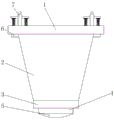
FIG. 1 is a front view of the structure of the present invention;
FIG. 2 is a schematic cross-sectional view of the present invention;
fig. 3 is a schematic cross-sectional view of the chucking device of the present invention.
In the figure: 1. mounting a plate; 2. a lamp shade; 3. installing a cylinder body; 4. fixing the cylinder; 5. a glass cover; 6. a limiting block; 7. a clamping device; 8. a mounting seat; 9. an illuminating lamp body; 10. a limiting hole; 11. a limiting rod; 12. a compression spring; 13. a connecting plate; 14. positioning the telescopic rod; 15. inserting a rod; 16. a first card slot; 17. a first clamping block; 18. a jack; 19. a limiting groove; 20. a second fixture block; 21. a second card slot; 22. and a balancing weight.
Detailed Description
The technical solutions in the embodiments of the present invention will be clearly and completely described below with reference to the drawings in the embodiments of the present invention, and it is obvious that the described embodiments are only a part of the embodiments of the present invention, and not all of the embodiments. All other embodiments, which can be derived by a person skilled in the art from the embodiments given herein without making any creative effort, shall fall within the protection scope of the present invention.
In the description herein, it is to be understood that the terms "center," "upper," "lower," "front," "rear," "left," "right," "vertical," "horizontal," "top," "bottom," "inner," "outer," and the like are used in the orientations and positional relationships indicated in the drawings to facilitate the description of the patent and to simplify the description, but do not indicate or imply that the referenced device or element must have a particular orientation, be constructed and operated in a particular orientation, and thus are not to be considered limiting of the patent. In the description of the present application, it should be noted that unless otherwise explicitly stated or limited, the terms "mounted," "connected," and "disposed" are to be construed broadly and can, for example, be fixedly connected, disposed, detachably connected, disposed, or integrally connected and disposed. The specific meaning of the above terms in this patent may be understood by those of ordinary skill in the art as appropriate.
Referring to fig. 1-3, an environment-friendly and energy-saving night scene lighting lamp for landscape engineering design comprises a mounting plate 1, a lampshade 2 is arranged at the bottom of the mounting plate 1, a mounting cylinder 3 is fixedly mounted at the bottom of the lampshade 2, a fixing cylinder 4 is arranged at the bottom of the mounting cylinder 3, the top of the fixing cylinder 4 penetrates through the inside of the mounting cylinder 3 and is in threaded connection with the mounting cylinder 3, a glass cover 5 is arranged at the bottom of the fixing cylinder 4, a mounting seat 8 is fixedly mounted at the bottom of the mounting plate 1, a lighting lamp body 9 is arranged at the bottom of the mounting seat 8, the lighting lamp body 9 is positioned inside the lampshade 2, clamping devices 7 are arranged at both sides of the top of the mounting plate 1, limiting holes 10 are formed at both sides of the top of the mounting plate 1, each clamping device 7 comprises a limiting rod 11, each limiting rod 11 penetrates through each limiting hole 10, a jack 18 is formed inside each limiting rod 11, an inserting rod 15 is arranged inside the inserting hole 18, the inserting rod 15 penetrates through the inserting hole 18 and is in sliding connection with the inserting hole 18, first clamping grooves 16 are formed in two sides of the bottom of the inserting rod 15, compression springs 12 are fixedly arranged on the top of the mounting plate 1 and located on two sides of the limiting rod 11, a connecting plate 13 is fixedly arranged on the top of the compression springs 12, a first clamping block 17 is fixedly arranged on the top of the connecting plate 13, the top of the first clamping block 17 is clamped inside the first clamping grooves 16, the lamp shade 2 can be opened and closed conveniently by arranging the mounting cylinder 3 and the fixing cylinder 4 to be matched with each other, when the illuminating lamp body 9 is damaged, a hand can be directly inserted into the lamp shade 2 by opening the lamp shade 2 to replace the illuminating lamp body 9, so that the illuminating lamp body 9 can be replaced conveniently, the compression springs 12 are arranged to extrude the connecting plate 13 and the first clamping block 17, so that the first clamping block 17 can be clamped into the first clamping grooves 16, the inserting rod 15 is fixed, so that the inserting rod 15 fixes and limits the limiting rod 11, the stability of the limiting rod 11 in use is improved, the stability of the lampshade 2 is further improved, meanwhile, the second clamping block 20 is pulled out, the inserting rod 15 can be pulled out, the inserting rod 15 is separated from the inner part of the jack 18, the lampshade 2 can be disassembled, the aim of conveniently installing and disassembling the lampshade 2 is achieved, the mounting seat 8 and the illuminating lamp body 9 are conveniently maintained and replaced, the problem that when the illuminating lamp body 9 or the mounting seat 8 is damaged, the whole device is directly abandoned is avoided, the aims of saving energy and protecting environment are achieved, the limiting blocks 6 are fixedly installed on two sides of the lampshade 2, the limiting blocks 6 are clamped at the bottom of the mounting plate 1 and used for limiting the lampshade 2 by arranging the limiting blocks 6, the positioning telescopic rods 14 are fixedly installed at the top of the mounting plate 1 and in the compression spring 12, the top of the positioning telescopic rod 14 is fixedly connected with the bottom of the connecting plate 13, the positioning telescopic rod 14 is used for limiting the connecting plate 13 and the first clamping block 17 to prevent the first clamping block 17 from deviating under the action of the compression spring 12, the top of the limiting rod 11 is provided with a limiting groove 19, the bottom of the limiting groove 19 is communicated with the jack 18, the limiting groove 19 is used for limiting the second clamping block 20, the top of the inserting rod 15 is provided with a second clamping groove 21, the second clamping groove 21 is positioned under the limiting groove 19, the top of the limiting rod 11 is provided with the second clamping block 20, the bottom of the second clamping block 20 penetrates through the limiting groove 19 and extends into the second clamping groove 21, the top of the second clamping block 20 is fixedly provided with a balancing weight 22, the second clamping block 20 and the second clamping groove 21 are arranged to be matched with each other for limiting the inserting rod 15, and the stability of the inserting rod 15 in use is improved, the left-right displacement of the inserting rod 15 is prevented, so that the first block 17 is separated from the inside of the first clamping groove 16.
When the lamp shade 2 is used, the lamp shade 2 can be opened and closed conveniently through the mutual matching of the installation cylinder 3 and the fixed cylinder 4, when the lighting lamp body 9 is damaged, the lamp shade 2 can be opened, hands can be directly inserted into the inside of the lamp shade 2 to replace the lighting lamp body 9, so that the lighting lamp body 9 can be replaced conveniently, the connecting plate 13 and the first fixture block 17 are extruded through the compression spring 12, the first fixture block 17 can be clamped into the first clamping groove 16, the insertion rod 15 can be fixed, the insertion rod 15 can fix and limit the limiting rod 11, the stability of the limiting rod 11 in use is improved, the stability of the lamp shade 2 is further improved, meanwhile, the second fixture block 20 is pulled out, the insertion rod 15 can be pulled out, the insertion rod 15 is separated from the inside of the insertion hole 18, so that the lamp shade 2 can be disassembled, and the aim of facilitating the installation and disassembly of the lamp shade 2 can be achieved, be convenient for maintain and change mount pad 8 and light body 9, avoided when light body 9 or mount pad 8 appear damaging, directly abandon whole device to energy-concerving and environment-protective purpose has been reached.
Although embodiments of the present invention have been shown and described, it will be appreciated by those skilled in the art that changes, modifications, substitutions and alterations can be made in these embodiments without departing from the principles and spirit of the utility model, the scope of which is defined in the appended claims and their equivalents.
Claims (6)
1. The utility model provides a landscape garden engineering design is with environmental protection and energy saving type night scene light, includes mounting panel (1), its characterized in that: the lamp shade is characterized in that a lamp shade (2) is arranged at the bottom of the mounting plate (1), a mounting barrel (3) is fixedly mounted at the bottom of the lamp shade (2), a fixing barrel (4) is arranged at the bottom of the mounting barrel (3), the top of the fixing barrel (4) penetrates through the inside of the mounting barrel (3) and is in threaded connection with the mounting barrel (3), a glass cover (5) is arranged at the bottom of the fixing barrel (4), a mounting seat (8) is fixedly mounted at the bottom of the mounting plate (1), a lighting lamp body (9) is arranged at the bottom of the mounting seat (8), the lighting lamp body (9) is located inside the lamp shade (2), clamping devices (7) are arranged on two sides of the top of the mounting plate (1), and limiting holes (10) are formed in two sides of the top of the mounting plate (1);
chucking device (7) include gag lever post (11), gag lever post (11) run through in spacing hole (10), jack (18) have been seted up to the inside of gag lever post (11), the inside of jack (18) is provided with inserted bar (15), inserted bar (15) run through in jack (18) and with jack (18) sliding connection, first draw-in groove (16) have all been seted up to the both sides of inserted bar (15) bottom, the equal fixed mounting in both sides that mounting panel (1) top just is located gag lever post (11) has compression spring (12), the top fixed mounting of compression spring (12) has connecting plate (13), the top fixed mounting of connecting plate (13) has first fixture block (17), the top card of first fixture block (17) is in the inside of first draw-in groove (16).
2. The environment-friendly and energy-saving night-scene illuminating lamp for landscape architectural design according to claim 1, wherein: the lamp shade is characterized in that limiting blocks (6) are fixedly mounted on two sides of the lamp shade (2), and the limiting blocks (6) are clamped at the bottom of the mounting plate (1).
3. The environment-friendly and energy-saving night-scene illuminating lamp for landscape architectural design according to claim 1, wherein: the top of mounting panel (1) and the inside fixed mounting that is located compression spring (12) have location telescopic link (14), the bottom fixed connection of the top of location telescopic link (14) and connecting plate (13).
4. The environment-friendly and energy-saving night-scene illuminating lamp for landscape architectural design according to claim 1, wherein: the top of the limiting rod (11) is provided with a limiting groove (19), and the bottom of the limiting groove (19) is communicated with the jack (18).
5. The environment-friendly and energy-saving night-scene illuminating lamp for landscape architectural design according to claim 1, wherein: a second clamping groove (21) is formed in the top of the inserting rod (15), and the second clamping groove (21) is located right below the limiting groove (19).
6. The environment-friendly and energy-saving night-scene illuminating lamp for landscape architectural design according to claim 1, wherein: the top of gag lever post (11) is provided with second fixture block (20), the bottom of second fixture block (20) runs through in spacing groove (19) and extends to the inside of second draw-in groove (21), the top fixed mounting of second fixture block (20) has balancing weight (22).
Priority Applications (1)
| Application Number | Priority Date | Filing Date | Title |
|---|---|---|---|
| CN202121498854.9U CN215335957U (en) | 2021-07-03 | 2021-07-03 | Landscape garden engineering design is with environmental protection and energy saving type night scene light |
Applications Claiming Priority (1)
| Application Number | Priority Date | Filing Date | Title |
|---|---|---|---|
| CN202121498854.9U CN215335957U (en) | 2021-07-03 | 2021-07-03 | Landscape garden engineering design is with environmental protection and energy saving type night scene light |
Publications (1)
| Publication Number | Publication Date |
|---|---|
| CN215335957U true CN215335957U (en) | 2021-12-28 |
Family
ID=79564202
Family Applications (1)
| Application Number | Title | Priority Date | Filing Date |
|---|---|---|---|
| CN202121498854.9U Active CN215335957U (en) | 2021-07-03 | 2021-07-03 | Landscape garden engineering design is with environmental protection and energy saving type night scene light |
Country Status (1)
| Country | Link |
|---|---|
| CN (1) | CN215335957U (en) |
Cited By (1)
| Publication number | Priority date | Publication date | Assignee | Title |
|---|---|---|---|---|
| CN114877295A (en) * | 2022-06-21 | 2022-08-09 | 深圳市美斯特光电技术有限公司 | LED high-power lighting lamp convenient to mount and mounting method thereof |
-
2021
- 2021-07-03 CN CN202121498854.9U patent/CN215335957U/en active Active
Cited By (2)
| Publication number | Priority date | Publication date | Assignee | Title |
|---|---|---|---|---|
| CN114877295A (en) * | 2022-06-21 | 2022-08-09 | 深圳市美斯特光电技术有限公司 | LED high-power lighting lamp convenient to mount and mounting method thereof |
| CN114877295B (en) * | 2022-06-21 | 2023-06-09 | 深圳市美斯特光电技术有限公司 | LED high-power lighting lamp convenient to install and installation method thereof |
Similar Documents
| Publication | Publication Date | Title |
|---|---|---|
| CN215335957U (en) | Landscape garden engineering design is with environmental protection and energy saving type night scene light | |
| CN205299408U (en) | LED street lamp casing and LED street lamp | |
| CN208566337U (en) | A kind of domestic type LED double-side luminous flat lamp | |
| CN202902063U (en) | LED wall lamp | |
| CN215929327U (en) | Lighting device with adjustable brightness | |
| CN217329516U (en) | Wall lamp structure with monitoring function | |
| CN220397403U (en) | Intelligent household lamp easy to disassemble and assemble | |
| CN216113660U (en) | Energy-saving lamp mounting base convenient to adjust | |
| CN204629262U (en) | LED kitchen guarding's lamp | |
| CN208919887U (en) | A kind of energy-saving wall lamp | |
| CN219889419U (en) | Festival color lamp with replaceable lamp shade | |
| CN217635447U (en) | Cabinet lamp capable of intelligently controlling light intensity | |
| CN217030990U (en) | Ceiling lamp convenient to installation | |
| CN217899687U (en) | Novel human body induction and stepless dimming wall lamp | |
| CN212081164U (en) | Lamp mounting structure | |
| CN213071906U (en) | From lighting distribution box device of area illumination formula | |
| CN215597141U (en) | LED underground lamp | |
| CN212408442U (en) | Assembled lamps and lanterns hoisting structure | |
| CN219433170U (en) | Hoist and mount position adjustable light | |
| CN217635211U (en) | Installation casing of view lighting lamp group | |
| CN218544132U (en) | LED light convenient to dismouting | |
| CN213237177U (en) | Energy-saving control device for indoor lighting lamp | |
| CN217928477U (en) | Lighting lamp for security protection | |
| CN214008951U (en) | External drive panel light | |
| CN219433163U (en) | Lamp strip structure for LED lamp |
Legal Events
| Date | Code | Title | Description |
|---|---|---|---|
| GR01 | Patent grant | ||
| GR01 | Patent grant |