CN211160799U - Punch press garbage collection device - Google Patents
Punch press garbage collection device Download PDFInfo
- Publication number
- CN211160799U CN211160799U CN201921750860.1U CN201921750860U CN211160799U CN 211160799 U CN211160799 U CN 211160799U CN 201921750860 U CN201921750860 U CN 201921750860U CN 211160799 U CN211160799 U CN 211160799U
- Authority
- CN
- China
- Prior art keywords
- waste
- base station
- slide
- motor
- punching press
- Prior art date
- Legal status (The legal status is an assumption and is not a legal conclusion. Google has not performed a legal analysis and makes no representation as to the accuracy of the status listed.)
- Active
Links
Images



Landscapes
- Cleaning In General (AREA)
Abstract
The utility model discloses a punch press waste collecting device, the utility model relates to the technical field of punching machines, which comprises a punching base station, a punching flat plate is arranged at the top of the punching base station, a waste collecting box is arranged at one side of the punching base station, a fixed block is arranged at the front surface of the punching base station, a waste slide seat is arranged at the top of the fixed block, a waste slide groove is arranged in the waste slide seat, a slide block is arranged at one side of the waste slide groove, a cleaning brush is arranged at the bottom of the slide block, a stator slide table is arranged at the top of a second linear motor, the utility model drives the cleaning brush by a linear motor to push metal waste in the waste slide groove to the inside of the waste collecting box, accelerates the movement of the waste, realizes automatic cleaning of the waste, and stretches into the waste collecting box by an electromagnet, thereby being beneficial to, is beneficial to quickly removing the metal waste.
Description
Technical Field
The utility model belongs to the technical field of the punch press, concretely relates to punch press garbage collection device.
Background
The punch press is a punching press type press, in national production, the punching process is efficient due to the fact that materials and energy are saved compared with the traditional machining, punching production is mainly directed to plates, after the plates are punched, waste materials are frequently generated on a punching flat plate, the treatment efficiency of the waste materials is directly related to the machining efficiency of the plates, and a good waste material treatment device can improve the machining efficiency of the plates.
But punch press garbage collection device on the existing market can not satisfy the operation requirement, and processing waste material often piles up on the junk slide, needs artifical supplementary clearance, consumes the manpower, and the waste material in the waste material box is piled up and is unfavorable for quick clearance to go out together, based on the problem that appears above, provides a punch press garbage collection device.
Disclosure of Invention
The utility model aims at providing a punch press garbage collection device to the collection process of the waste material that proposes consumes the manpower in solving above-mentioned background art, and the waste material is unfavorable for the problem of clearing away fast than piling in the waste material box.
In order to achieve the above object, the utility model provides a following technical scheme: the utility model provides a punch press garbage collection device, includes the punching press base station, the punching press is dull and stereotyped at the top of punching press base station is installed, garbage collection box is installed to one side of punching press base station, the front surface mounting of punching press base station has the fixed block, and the top of fixed block installs the waste material slide, the waste material spout has been seted up to the inside of waste material slide, and one side of waste material spout installs the slider, the brush cleaner is installed to the bottom of slider, the front surface of waste material slide passes through bolt fixedly connected with second linear electric motor, the stator slip table is installed at second linear electric motor's top, and installs the active cell slider in the top of stator slip table, bolt fixedly connected with connecting rod is passed.
Preferably, electric telescopic handle is installed to one side of garbage collection box, and electric telescopic handle's top installs the footstock, the top of footstock rotates through the pivot and is connected with the horizontal pole, and the top of horizontal pole installs the motor, the electro-magnet is installed to the one end of horizontal pole, the travelling bogie is installed to one side of electric telescopic handle.
Preferably, a mounting seat is installed on one side of the waste collecting box, a first linear motor is installed at the top of the mounting seat, and a cleaning rod is installed on one side of the first linear motor.
Preferably, the front surface mounting of garbage collection box has the switch, electric telescopic handle, motor, first linear electric motor, electro-magnet and second linear electric motor all with switch electric connection.
Preferably, the electromagnet is of a cylindrical structure, and a waterproof coating is arranged on the surface of the electromagnet.
Compared with the prior art, the beneficial effects of the utility model are that:
(1) The utility model discloses a linear electric motor drive slider drives the metal waste material of brush cleaner in with the waste material spout and promotes to the inside of garbage collection box for the removal of waste material realizes cleaning the waste material automatically, improves the collection speed of waste material, avoids the waste material to plug up the waste material slide.
(2) The utility model discloses an in the electro-magnet stretched into the garbage collection box, with the inside metal waste suction of garbage collection box, then unified placing on the travelling bogie, be favorable to reducing artifical clearance intensity of labour, be favorable to cleaing away fast of metal waste, keep the inside enough space of garbage collection box, be favorable to lasting processing of panel.
Drawings
Fig. 1 is a schematic structural view of the present invention;
FIG. 2 is a top view of the waste collection box and the stamping base of the present invention;
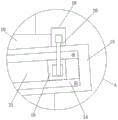
FIG. 3 is an enlarged view of portion A of FIG. 1;
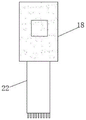
FIG. 4 is a schematic structural view of the slide block and the cleaning brush of the present invention;
Fig. 5 is a circuit block diagram of the present invention;
In the figure: 1-transporting the trolley; 2, an electric telescopic rod; 3-a top seat; 4-a motor; 5-a cross bar; 6-an electromagnet; 7-a first linear motor; 8-stamping a flat plate; 9-a sweeping rod; 10-punching the base platform; 11-fixing block; 12-a waste collection box; 13-a switch; 14-a second linear motor; 15-a waste slide; 16-a mounting seat; 17-a waste chute; 18-a slide block; 19-a mover slide; 20-a connecting rod; 21-a stator ramp; 22-cleaning brush.
Detailed Description
The technical solutions in the embodiments of the present invention will be described clearly and completely with reference to the accompanying drawings in the embodiments of the present invention, and it is obvious that the described embodiments are only some embodiments of the present invention, not all embodiments. Based on the embodiments in the present invention, all other embodiments obtained by a person skilled in the art without creative work belong to the protection scope of the present invention.
Referring to fig. 1-5, the present invention provides the following technical solutions: a punch press waste collecting device comprises a punching base 10, a punching flat plate 8 is arranged at the top of the punching base 10, a waste collecting box 12 is arranged at one side of the punching base 10, a fixing block 11 is arranged on the front surface of the punching base 10, and the top of the fixed block 11 is provided with a waste material sliding seat 15, the waste material sliding seat 15 is in an inclined state on the front surface of the stamping base station 10, the waste material is pushed into a waste material sliding groove 17, part of the waste material can slide and enter the waste material collecting box 12, the waste material sliding groove 17 is arranged inside the waste material sliding seat 15, and one side of the waste chute 17 is provided with a slide block 18, the bottom of the slide block 18 is provided with a cleaning brush 22, the front surface of the waste slide seat 15 is fixedly connected with a second linear motor 14 through bolts, the top of the second linear motor 14 is provided with a stator sliding table 21, and a rotor slider 19 is arranged above the stator sliding table 21, and one side of the rotor slider 19 is fixedly connected with a connecting rod 20 through a bolt.
Further, electric telescopic handle 2 is installed to one side of garbage collection box 12, and footstock 3 is installed at electric telescopic handle 2's top, and footstock 3's top is rotated through the pivot and is connected with horizontal pole 5, and motor 4 is installed at horizontal pole 5's top, and electro-magnet 6 is installed to the one end of horizontal pole 5, and travelling bogie 1 is installed to one side of electric telescopic handle 2.
Further, a mounting seat 16 is installed on one side of the waste collecting box 12, a first linear motor 7 is installed on the top of the mounting seat 16, a cleaning rod 9 is installed on one side of the first linear motor 7, one end of the cleaning rod 9 is installed on a linear coil on the first linear motor 7 and then is driven to perform linear motion, and waste on the top of the stamping flat plate 8 is swept away.
further, a switch 13 is mounted on the front surface of the waste collection box 12, the electric telescopic rod 2, the motor 4, the first linear motor 7, the electromagnet 6 and the second linear motor 14 are electrically connected with the switch 13, the electric telescopic rod 9 adopts HB-DJ806 and rated voltage 380V, the motor 4 adopts a Y132M-4 three-phase motor and rated voltage is 220V, and the first linear motor 7 and the second linear motor 14 both adopt an M L A20 linear motor and rated voltage is 220V.
Further, the electromagnet 6 is of a cylindrical structure, and a waterproof coating is arranged on the surface of the electromagnet 6.
The utility model discloses a theory of operation and use flow: during the use, the user switches on the external power supply with the garbage collection device, first linear electric motor 7 drives cleaning rod 9 and moves on punching press dull and stereotyped 8, the waste material on punching press dull and stereotyped 8 is swept into waste material spout 17, active cell slider 19 on second linear electric motor 14 moves on stator slip table 21, drive slider 18 and cleaning brush 22 simultaneously and move, cleaning brush 22 sweeps the waste material in the waste material spout 17 to the inside of garbage collection box 12, electric telescopic handle 2 drives horizontal pole 5 and electro-magnet 6 and moves down, electro-magnet 6 catches the waste material of garbage collection box 12 inside, electric telescopic handle 2 rises again, motor 4 main shaft drives horizontal pole 5 and moves, horizontal pole 5 drives electro-magnet 6 and moves, electro-magnet 6 moves to transport trolley 1 top, after electro-magnet 6 cuts off the power supply, the waste material drops on transport trolley 1, transport the waste material to recovery department.
Although embodiments of the present invention have been shown and described, it will be appreciated by those skilled in the art that changes, modifications, substitutions and alterations can be made in these embodiments without departing from the principles and spirit of the invention, the scope of which is defined in the appended claims and their equivalents.
Claims (5)
1. The utility model provides a punch press garbage collection device, includes punching press base station (10), dull and stereotyped (8) of punching press are installed at the top of punching press base station (10), garbage collection box (12), its characterized in that are installed to one side of punching press base station (10): the utility model discloses a punching press base station, including punching press base station (10), the preceding surface mounting of punching press base station (10) has fixed block (11), and the top of fixed block (11) installs waste slide (15), waste material spout (17) have been seted up to the inside of waste slide (15), and one side of waste material spout (17) installs slider (18), sweeper brush (22) are installed to the bottom of slider (18), the front surface of waste material slide (15) passes through bolt fixedly connected with second linear electric motor (14), stator slip table (21) are installed at the top of second linear electric motor (14), and install active cell slider (19) to the top of stator slip table (21), bolt fixedly connected with connecting rod (20) is passed through to one side of active cell slider (19).
2. The punch press waste collection device of claim 1, wherein: electric telescopic handle (2) are installed to one side of garbage collection box (12), and electric telescopic handle's (2) top installs footstock (3), the top of footstock (3) is rotated through the pivot and is connected with horizontal pole (5), and installs motor (4) at the top of horizontal pole (5), electro-magnet (6) are installed to the one end of horizontal pole (5), travelling bogie (1) is installed to one side of electric telescopic handle (2).
3. The punch press waste collection device of claim 1, wherein: a mounting seat (16) is installed on one side of the waste collecting box (12), a first linear motor (7) is installed at the top of the mounting seat (16), and a cleaning rod (9) is installed on one side of the first linear motor (7).
4. The punch press waste collection device of claim 2, wherein: the waste collection box is characterized in that a switch (13) is installed on the front surface of the waste collection box (12), and the electric telescopic rod (2), the motor (4), the first linear motor (7), the electromagnet (6) and the second linear motor (14) are all electrically connected with the switch (13).
5. The punch press waste collection device of claim 2, wherein: the electromagnet (6) is of a cylindrical structure, and a waterproof coating is arranged on the surface of the electromagnet (6).
Priority Applications (1)
| Application Number | Priority Date | Filing Date | Title |
|---|---|---|---|
| CN201921750860.1U CN211160799U (en) | 2019-10-18 | 2019-10-18 | Punch press garbage collection device |
Applications Claiming Priority (1)
| Application Number | Priority Date | Filing Date | Title |
|---|---|---|---|
| CN201921750860.1U CN211160799U (en) | 2019-10-18 | 2019-10-18 | Punch press garbage collection device |
Publications (1)
| Publication Number | Publication Date |
|---|---|
| CN211160799U true CN211160799U (en) | 2020-08-04 |
Family
ID=71820762
Family Applications (1)
| Application Number | Title | Priority Date | Filing Date |
|---|---|---|---|
| CN201921750860.1U Active CN211160799U (en) | 2019-10-18 | 2019-10-18 | Punch press garbage collection device |
Country Status (1)
| Country | Link |
|---|---|
| CN (1) | CN211160799U (en) |
Cited By (1)
| Publication number | Priority date | Publication date | Assignee | Title |
|---|---|---|---|---|
| CN116809796A (en) * | 2023-08-28 | 2023-09-29 | 苏州弘能精密模具有限公司 | Waste collection equipment for stamping production line |
-
2019
- 2019-10-18 CN CN201921750860.1U patent/CN211160799U/en active Active
Cited By (1)
| Publication number | Priority date | Publication date | Assignee | Title |
|---|---|---|---|---|
| CN116809796A (en) * | 2023-08-28 | 2023-09-29 | 苏州弘能精密模具有限公司 | Waste collection equipment for stamping production line |
Similar Documents
| Publication | Publication Date | Title |
|---|---|---|
| CN211160799U (en) | Punch press garbage collection device | |
| CN219336386U (en) | Cutting machine convenient to collect slag | |
| CN201649009U (en) | Rear-barrel electric sweeping machine | |
| CN205653731U (en) | Gardens are with high -efficient cleaning device of leaf | |
| CN208583866U (en) | A kind of environmental protection press surface garbage recovery device | |
| CN201250395Y (en) | Power-driven sweeping machine | |
| CN214488211U (en) | Paint bucket cleaning machine | |
| CN216599534U (en) | Photovoltaic board deashing equipment | |
| CN114345025B (en) | Automatic cleaning device and cleaning method for SVG water-cooled radiator | |
| CN211200466U (en) | Well lid extraction element is used in communication engineering construction | |
| CN214646224U (en) | A accumulator for carton production | |
| CN211392559U (en) | Be used for municipal environment-friendly rubbish clean-up equipment | |
| CN212384443U (en) | Punching waste automatic clearing tool of fast punching machine | |
| CN214194318U (en) | Leaf cleaning device | |
| CN212042157U (en) | Slotting device convenient to clean for drawer bottom plate production | |
| CN210898033U (en) | Smart power grids switch board | |
| CN210304983U (en) | Punch press is used for collecting waste material device | |
| CN209538148U (en) | A kind of river floating garbage recyclable device | |
| CN112808726A (en) | Paint bucket cleaning machine | |
| CN216727636U (en) | City gardens device of environmental protection | |
| CN218855160U (en) | Garbage compressor convenient to clearance | |
| CN219690439U (en) | Automatic open channel foreign matter cleaning device | |
| CN214568258U (en) | Feeding device of environment-friendly equipment | |
| CN211621929U (en) | Desilting device of building drainage ditch | |
| CN217310091U (en) | Dust treatment device for forging workshop |
Legal Events
| Date | Code | Title | Description |
|---|---|---|---|
| GR01 | Patent grant | ||
| GR01 | Patent grant |