CN211142910U - Safety barrier is used in highway maintenance - Google Patents
Safety barrier is used in highway maintenance Download PDFInfo
- Publication number
- CN211142910U CN211142910U CN201921736092.4U CN201921736092U CN211142910U CN 211142910 U CN211142910 U CN 211142910U CN 201921736092 U CN201921736092 U CN 201921736092U CN 211142910 U CN211142910 U CN 211142910U
- Authority
- CN
- China
- Prior art keywords
- hollow tube
- seted
- slot
- slidable mounting
- horizontal pole
- Prior art date
- Legal status (The legal status is an assumption and is not a legal conclusion. Google has not performed a legal analysis and makes no representation as to the accuracy of the status listed.)
- Expired - Fee Related
Links
Images

Abstract
The utility model belongs to the technical field of traffic safety facility, especially, be a safety barrier for highway maintenance, the on-line screen storage device comprises a base, the top of base is equipped with the hollow tube, slidable mounting has the bracing piece in the hollow tube, the top of bracing piece extends to outside the hollow tube and has seted up the slot, a plurality of first jacks have all been seted up on the both sides inner wall of slot, slidable mounting has the horizontal pole in the first jack, the draw-in groove has been seted up on one side of horizontal pole, the one end that the draw-in groove was kept away from to the horizontal pole is rotated and is installed the buckle, slidable mounting has the inserted bar in the slot, the inserted bar runs through a plurality of horizontal poles, the top fixed mounting of inserted. The utility model discloses simple structure, the practicality is strong, can be quick assemble and dismantle whole safety barrier for safety barrier is more convenient when carrying out remote transportation.
Description
Technical Field
The utility model relates to a traffic safety facility technical field especially relates to a safety barrier is used in highway maintenance.
Background
The patent document with the publication number of CN205444042U discloses a safety barrier for road maintenance, which comprises a base, wherein a support rod is arranged on the base, a plurality of transverse connecting rods are arranged on the support rod, one end of each transverse connecting rod is provided with a rotary connecting piece, and the other end of each transverse connecting rod is provided with a clamping groove corresponding to the rotary connecting piece; the upper end of the supporting rod is provided with a reflective ball.
However, the prior art has the defects that the device occupies a large space, so that the device is inconvenient to store in the transportation process, and the safety guardrail for highway maintenance is provided.
SUMMERY OF THE UTILITY MODEL
The utility model aims at solving the defects existing in the prior art and providing a safety barrier for highway maintenance.
In order to achieve the above purpose, the utility model adopts the following technical scheme: the utility model provides a safety barrier for highway maintenance, includes the base, the top of base is equipped with the hollow tube, slidable mounting has the bracing piece in the hollow tube, the top of bracing piece extends to outside the hollow tube and has seted up the slot, a plurality of first jacks have all been seted up on the both sides inner wall of slot, slidable mounting has the horizontal pole in the first jack, the draw-in groove has been seted up on one side of horizontal pole, the one end that the draw-in groove was kept away from to the horizontal pole is rotated and is installed the buckle, slidable mounting has the inserted bar in the slot, the inserted bar runs through a plurality of horizontal poles, the top fixed mounting of inserted bar has reflective ball, threaded connection.
Preferably, the top of the base is provided with an internal thread groove, the hollow pipe is provided with an external thread, and the hollow pipe is in threaded connection with the internal thread groove.
Preferably, the spout has all been seted up to the both sides of bracing piece, slidable mounting has the slider in the spout, and one side that two sliders kept away from each other all extends outside the spout and with the inner wall fixed connection of hollow tube.
Preferably, the cross rod is sleeved with a limiting ring, and the limiting ring is in contact with the supporting rod.
Preferably, a second jack is formed in the cross rod, and the inserted rod is connected with the second jack in a sliding mode.
Compared with the prior art, the beneficial effects of the utility model are that: at first, the device cooperatees through bracing piece, horizontal pole and inserted bar, extracts the inserted bar earlier, loses the fixed back of inserted bar and can take out the horizontal pole from the bracing piece and leave, rotates the hollow tube at last, separates hollow tube and base to make whole safety barrier can fast assembly and dismantlement, after dismantling, occupation space is less, and it is more convenient to transport.
The utility model discloses simple structure, the practicality is strong, can be quick assemble and dismantle whole safety barrier for safety barrier is more convenient when carrying out remote transportation.
Drawings
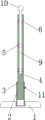
FIG. 1 is a front sectional view of the present invention;
fig. 2 is a schematic side view of the cross-sectional structure of the present invention.
In the figure: 1. a base; 2. a hollow tube; 3. a support bar; 4. a slot; 5. a first jack; 6. a cross bar; 7. a card slot; 8. buckling; 9. inserting a rod; 10. a light reflecting ball; 11. and (5) screwing the screw.
Detailed Description
The technical solutions in the embodiments of the present invention will be described clearly and completely with reference to the accompanying drawings in the embodiments of the present invention, and it is obvious that the described embodiments are only some embodiments of the present invention, not all embodiments. Based on the embodiments in the present invention, all other embodiments obtained by a person skilled in the art without creative work belong to the protection scope of the present invention.
Referring to fig. 1-2, the present invention provides a technical solution: a safety barrier for highway maintenance comprises a base 1, wherein a hollow tube 2 is arranged at the top of the base 1, a support rod 3 is arranged in the hollow tube 2 in a sliding manner, the top end of the support rod 3 extends out of the hollow tube 2 and is provided with a slot 4, a plurality of first jacks 5 are respectively arranged on the inner walls of two sides of the slot 4, a cross rod 6 is arranged in the first jacks 5 in the sliding manner, a clamping slot 7 is formed in one side of the cross rod 6, a buckle 8 is rotatably arranged at one end, away from the clamping slot 7, of the cross rod 6, an inserting rod 9 is arranged in the slot 4 in a sliding manner, the inserting rod 9 penetrates through the cross rods 6, a reflective ball 10 is fixedly arranged at;
the top of the base 1 is provided with an internal thread groove, the hollow tube 2 is provided with an external thread, the hollow tube 2 is in threaded connection with the internal thread groove, two sides of the support rod 3 are both provided with a chute, a slide block is arranged in the chute in a sliding way, one side of the two slide blocks, which is far away from each other, extends out of the chute and is fixedly connected with the inner wall of the hollow tube 2, the cross rod 6 is sleeved with a limit ring, the limit ring is contacted with the support rod 3, the cross rod 6 is provided with a second jack, the insert rod 9 is in sliding connection with the second jack, the insert rod 9 is firstly pulled out through the matching of the support rod 3, the cross rod 6 can be pulled away from the support rod 3 after losing the fixation of the insert rod 9, finally the hollow tube 2 is rotated to separate the hollow tube 2 from the base 1, thereby the whole safety guardrail can be rapidly assembled and disassembled, the practicality is strong, can be quick assemble and dismantle whole guardrail for guardrail is more convenient when carrying out remote transportation.
The working principle is as follows: during the use, a plurality of safety barriers can be through buckle 8 and draw-in groove 7 end to end, form the isolation region, reflection of light ball 10 can play the warning effect, bracing piece 3 can carry out altitude mixture control, it is fixed that screw 11 is screwed up to the reuse after adjusting, be used for adapting to the high drop on ground, make every safety barrier all be in same height, make things convenient for buckle 8 and draw-in groove 7 block, when needs carry out remote transportation to safety barrier, extract inserted bar 9 earlier, can take out horizontal pole 6 from bracing piece 3 after losing inserted bar 9's fixing, rotate hollow tube 2 at last, separate hollow tube 2 and base 1, whole safety barrier has been split opening this moment, when carrying out on-vehicle transportation, can practice thrift a large amount of spaces, make the single transportation quantity more.
It should be noted that the device structure and the accompanying drawings of the present invention mainly describe the principle of the present invention, and in the technology of this design principle, the settings of the power mechanism and the control system of the device are not completely described, and those skilled in the art can clearly know the specifics of the power mechanism and the control system thereof on the premise that those skilled in the art understand the principle of the present invention.
The above, only be the concrete implementation of the preferred embodiment of the present invention, but the protection scope of the present invention is not limited thereto, and any person skilled in the art is in the technical scope of the present invention, according to the technical solution of the present invention and the utility model, the concept of which is equivalent to replace or change, should be covered within the protection scope of the present invention.
Claims (5)
1. The utility model provides a safety barrier is used in highway maintenance, includes base (1), its characterized in that: the top of base (1) is equipped with hollow tube (2), slidable mounting has bracing piece (3) in hollow tube (2), the top of bracing piece (3) extends to hollow tube (2) and has seted up slot (4) outward, a plurality of first jack (5) have all been seted up on the both sides inner wall of slot (4), slidable mounting has horizontal pole (6) in first jack (5), draw-in groove (7) have been seted up on one side of horizontal pole (6), the one end that draw-in groove (7) were kept away from in horizontal pole (6) is rotated and is installed buckle (8), slidable mounting has inserted bar (9) in slot (4), inserted bar (9) run through a plurality of horizontal poles (6), the top fixed mounting of inserted bar (9) has reflective ball (10), threaded connection has screw (11) of screwing up on hollow tube (2).
2. A safety guard rail for road maintenance according to claim 1, wherein: the top of the base (1) is provided with an internal thread groove, the hollow pipe (2) is provided with an external thread, and the hollow pipe (2) is in threaded connection with the internal thread groove.
3. A safety guard rail for road maintenance according to claim 1, wherein: the spout has all been seted up to the both sides of bracing piece (3), slidable mounting has the slider in the spout, and one side that two sliders kept away from each other all extends outside the spout and with the inner wall fixed connection of hollow tube (2).
4. A safety guard rail for road maintenance according to claim 1, wherein: the limiting ring is sleeved on the cross rod (6) and is in contact with the supporting rod (3).
5. A safety guard rail for road maintenance according to claim 1, wherein: and a second jack is formed in the cross rod (6), and the inserted rod (9) is connected with the second jack in a sliding manner.
Priority Applications (1)
| Application Number | Priority Date | Filing Date | Title |
|---|---|---|---|
| CN201921736092.4U CN211142910U (en) | 2019-10-16 | 2019-10-16 | Safety barrier is used in highway maintenance |
Applications Claiming Priority (1)
| Application Number | Priority Date | Filing Date | Title |
|---|---|---|---|
| CN201921736092.4U CN211142910U (en) | 2019-10-16 | 2019-10-16 | Safety barrier is used in highway maintenance |
Publications (1)
| Publication Number | Publication Date |
|---|---|
| CN211142910U true CN211142910U (en) | 2020-07-31 |
Family
ID=71771079
Family Applications (1)
| Application Number | Title | Priority Date | Filing Date |
|---|---|---|---|
| CN201921736092.4U Expired - Fee Related CN211142910U (en) | 2019-10-16 | 2019-10-16 | Safety barrier is used in highway maintenance |
Country Status (1)
| Country | Link |
|---|---|
| CN (1) | CN211142910U (en) |
Cited By (1)
| Publication number | Priority date | Publication date | Assignee | Title |
|---|---|---|---|---|
| CN115288059A (en) * | 2022-09-13 | 2022-11-04 | 山东鲁润塑业股份有限公司 | Composite highway safety guardrail |
-
2019
- 2019-10-16 CN CN201921736092.4U patent/CN211142910U/en not_active Expired - Fee Related
Cited By (1)
| Publication number | Priority date | Publication date | Assignee | Title |
|---|---|---|---|---|
| CN115288059A (en) * | 2022-09-13 | 2022-11-04 | 山东鲁润塑业股份有限公司 | Composite highway safety guardrail |
Similar Documents
| Publication | Publication Date | Title |
|---|---|---|
| CN210768107U (en) | Building guardrail for civil engineering | |
| CN211142910U (en) | Safety barrier is used in highway maintenance | |
| CN210396364U (en) | Movable type enclosure for constructional engineering construction | |
| CN111560887B (en) | Guardrail for highway construction | |
| CN210636325U (en) | Warning sign convenient to fold and fix for municipal road maintenance | |
| CN208010040U (en) | It is a kind of to facilitate section construction construction enclosure wall | |
| CN209874658U (en) | Rail guard is used in bridge construction | |
| CN215255155U (en) | Civil engineering combined guardrail | |
| CN210597127U (en) | Be applicable to rural highway guardrail device of low grade | |
| CN212614057U (en) | Security fence for construction | |
| CN210195445U (en) | Security fence support for electric power construction | |
| CN219908707U (en) | Municipal administration guardrail | |
| CN218291696U (en) | Folding type cone bucket | |
| CN215927038U (en) | House building afforestation protective structure | |
| CN210368756U (en) | Town road guardrail | |
| CN220620605U (en) | Building curtain wall convenient to installation | |
| CN216339209U (en) | Novel municipal works road jube | |
| CN219711177U (en) | Spliced fence for building construction | |
| CN218044086U (en) | Outdoor sun shade base easy to assemble and disassemble | |
| CN211851230U (en) | Museum construction is with place isolating device | |
| CN213142881U (en) | Road isolated column for municipal works | |
| CN213978744U (en) | Foldable guardrail is used in municipal administration | |
| CN217812791U (en) | A enclose shelves device for town road construction | |
| CN219691251U (en) | Municipal construction safety protection guardrail | |
| CN213063190U (en) | Fence support suitable for installing barbed wire rolling cage on line cement fence |
Legal Events
| Date | Code | Title | Description |
|---|---|---|---|
| GR01 | Patent grant | ||
| GR01 | Patent grant | ||
| CF01 | Termination of patent right due to non-payment of annual fee |
Granted publication date: 20200731 Termination date: 20211016 |
|
| CF01 | Termination of patent right due to non-payment of annual fee |