CN210768107U - Building guardrail for civil engineering - Google Patents
Building guardrail for civil engineering Download PDFInfo
- Publication number
- CN210768107U CN210768107U CN201921256647.5U CN201921256647U CN210768107U CN 210768107 U CN210768107 U CN 210768107U CN 201921256647 U CN201921256647 U CN 201921256647U CN 210768107 U CN210768107 U CN 210768107U
- Authority
- CN
- China
- Prior art keywords
- connecting plate
- fixed frame
- rod
- guardrail
- civil engineering
- Prior art date
- Legal status (The legal status is an assumption and is not a legal conclusion. Google has not performed a legal analysis and makes no representation as to the accuracy of the status listed.)
- Expired - Fee Related
Links
Images


Abstract
The utility model discloses a building guardrail for civil engineering, including the fixed frame in a left side, erect fender rod, horizontal fender rod and protection awl, the inboard of the fixed frame in a left side is provided with left connecting plate, and the upper and lower both ends of left connecting plate all install first installation pole to the top of first installation pole is connected for the bearing with the medial surface of the fixed frame in a left side, the leading flank of left side connecting plate is seted up flutedly, the right flank of first installation pole is fixed with horizontal fender rod. This building guardrail for civil engineering is provided with left fixed frame and first installation pole, first installation pole is connected for the bearing with the fixed frame in left, with the same reason, the fixed frame in right side and second installation pole also are connected for the bearing, and then make the fixed frame in left side of a guardrail and the fixed frame in right side of another guardrail can drive respectively and erect the fender rod and violently the fender rod and rotate, be convenient for from this to carrying out the concatenation of different angle contained angles between two guardrails, so that the guardrail is applicable to different application areas, the practicality and the convenience of guardrail have been improved.
Description
Technical Field
The utility model relates to a civil engineering technical field specifically is building guardrail for civil engineering.
Background
Civil engineering refers to a general term of a series of activities related to construction of houses, roads and the like, and in the process of construction and construction, civil engineering separates a construction site from an external area so as to warn external personnel, so that a building guardrail can be used, although the types of the building guardrails on the current market are various, certain defects exist, such as:
most of traditional building guardrails in the current market have the functions of splicing, dismounting and the like, but the traditional building guardrails cannot be spliced irregularly according to irregular use areas during splicing, so that more building guardrails can be used, and more building guardrails are wasted;
most of traditional building guardrails are spliced by using a clamping structure, the splicing firmness is low, the stability is low when the building guardrails are used in windy weather, and the building guardrails are easy to separate;
therefore, the building guardrail for civil engineering can well solve the problems.
SUMMERY OF THE UTILITY MODEL
An object of the utility model is to provide a building guardrail for civil engineering to solve the current market that above-mentioned background art provided on traditional building guardrail for civil engineering can not carry out anomalous concatenation, the lower problem of stability of concatenation.
In order to achieve the above object, the utility model provides a following technical scheme: a building guardrail for civil engineering comprises a left fixing frame, a vertical protective rod, a transverse protective rod and a protective cone, wherein a left connecting plate is arranged on the inner side of the left fixing frame, first mounting rods are mounted at the upper end and the lower end of the left connecting plate, the top end of each first mounting rod is connected with the inner side surface of the left fixing frame through a bearing, a groove is formed in the front side surface of the left connecting plate, the transverse protective rod is fixed on the right side surface of each first mounting rod, a right fixing frame is fixed at the right end of each transverse protective rod, a vertical protective rod is fixed on the rear side surface of each transverse protective rod, a protective cone is fixed at the top end of each vertical protective rod, a right connecting plate is arranged on the inner side of the right fixing frame, second mounting rods are fixed at the upper end and the lower end of the right connecting plate, the top ends of the second mounting rods are connected with the inner side surface of the, and the front side of the mounting groove is provided with a through hole, a right connecting plate is fixed on the outer side of the through hole, a pulling plate is arranged on the outer side of the front side of the right connecting plate, connecting columns are fixed at the upper end and the lower end of the inner side of the pulling plate, the outer side of each connecting column is connected with the right connecting plate through a return spring, and a mounting column is fixed on the inner side of the pulling plate.
Preferably, the left fixed frame and the right fixed frame are both of a U-shaped structure, the outer dimensions of the left fixed frame and the right fixed frame are the same, the opening directions of the left fixed frame and the right fixed frame are opposite, and meanwhile, the left fixed frame and the left connecting plate form a rotating structure through the first mounting rod.
Preferably, the depth of the groove is smaller than the thickness of the left connecting plate, the groove and the mounting column are arranged in a one-to-one correspondence mode, and the diameter of the groove is larger than that of the mounting column.
Preferably, the fixed frame in right side constitutes revolution mechanic through second installation pole and right connecting plate, and the right connecting plate passes through the mounting groove and constitutes dismantlement structure with left connecting plate.
Preferably, the pulling plate and the right connecting plate form a sliding structure through a connecting column and a return spring.
Compared with the prior art, the beneficial effects of the utility model are that: the building guardrail for civil engineering;
(1) the guardrail mounting device is provided with a left fixing frame and a first mounting rod, wherein the first mounting rod and the left fixing frame are connected through a bearing, and similarly, the right fixing frame and the second mounting rod are also connected through a bearing, so that the left fixing frame of one guardrail and the right fixing frame of another guardrail can respectively drive the vertical protection rod and the horizontal protection rod to rotate, and therefore splicing of different angle included angles between the two guardrails is facilitated, the guardrails are suitable for different use areas, and the practicability and convenience of the guardrails are improved;
(2) install left connecting plate and right connecting plate, through the setting of the arm-tie in the right connecting plate outside, be convenient for fix left connecting plate and right connecting plate through the inboard erection column of arm-tie, compare traditional block structure and unsmooth cooperation structure, the stability of this design is higher, increases whole guardrail and carries out stability and the fastness that uses in strong wind weather.
Drawings
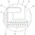
FIG. 1 is a schematic view of the overall structure of the present invention;
FIG. 2 is a schematic view of the main sectional structure of the left connecting plate and the right connecting plate of the present invention;
FIG. 3 is a schematic view of a right cross-sectional structure of the connection between the left connecting plate and the right connecting plate of the present invention;
fig. 4 is an enlarged schematic structural view of a portion a in fig. 3 according to the present invention.
In the figure: 1. a left fixed frame; 2. a first mounting bar; 3. a left connecting plate; 4. a groove; 5. erecting a guard bar; 6. a transverse guard bar; 7. a protection cone; 8. a right fixed frame; 9. a second mounting bar; 10. a right connecting plate; 11. pulling a plate; 12. mounting grooves; 13. a through hole; 14. mounting a column; 15. connecting columns; 16. a return spring.
Detailed Description
The technical solutions in the embodiments of the present invention will be described clearly and completely with reference to the accompanying drawings in the embodiments of the present invention, and it is obvious that the described embodiments are only some embodiments of the present invention, not all embodiments. Based on the embodiments in the present invention, all other embodiments obtained by a person skilled in the art without creative work belong to the protection scope of the present invention.
Referring to fig. 1-4, the present invention provides a technical solution: a building guardrail for civil engineering comprises a left fixing frame 1, a first mounting rod 2, a left connecting plate 3, a groove 4, a vertical protective rod 5, a transverse protective rod 6, a protective cone 7, a right fixing frame 8, a second mounting rod 9, a right connecting plate 10, a pulling plate 11, a mounting groove 12, a through hole 13, a mounting column 14, a connecting column 15 and a reset spring 16, wherein the left connecting plate 3 is arranged on the inner side of the left fixing frame 1, the first mounting rod 2 is mounted at the upper end and the lower end of the left connecting plate 3, the top end of the first mounting rod 2 is connected with the inner side surface of the left fixing frame 1 through a bearing, the groove 4 is formed in the front side surface of the left connecting plate 3, the transverse protective rod 6 is fixed on the right side surface of the first mounting rod 2, the right fixing frame 8 is fixed at the right end of the transverse protective rod 6, the vertical protective rod 5 is fixed on the rear side surface of the transverse protective rod 6, the protective cone 7 is fixed at the, second mounting rods 9 are fixed at the upper end and the lower end of a right connecting plate 10, the top ends of the second mounting rods 9 are connected with the inner side face of a right fixing frame 8 through bearings, a mounting groove 12 is formed in the inner portion of the right side face of the right connecting plate 10, a through hole 13 is formed in the front side face of the mounting groove 12, a right connecting plate 10 is fixed on the outer side of the through hole 13, a pulling plate 11 is arranged on the outer side of the front side face of the right connecting plate 10, connecting posts 15 are fixed at the upper end and the lower end of the inner side face of the pulling plate 11, the outer side of each connecting post 15 is connected with the right connecting plate 10 through a return spring 16;
the left fixing frame 1 and the right fixing frame 8 are both in a U-shaped structure, the outer dimensions of the left fixing frame 1 and the right fixing frame 8 are the same, the opening directions of the left fixing frame 1 and the right fixing frame 8 are opposite, and meanwhile, the left fixing frame 1 and the left connecting plate 3 form a rotating structure through the first mounting rod 2, so that the left fixing frame 1 and the right fixing frame 8 which are both in the U-shaped structure can rotate well, and splicing of different included angle angles among a plurality of guardrails is facilitated;
the depth of the groove 4 is smaller than the thickness of the left connecting plate 3, the grooves 4 are arranged in one-to-one correspondence with the mounting columns 14, the diameter of the groove 4 is larger than that of the mounting column 14, and the left connecting plate 3 and the right connecting plate 10 are fixed by the mounting columns 14 conveniently through the design of the grooves 4;
the right fixing frame 8 and the right connecting plate 10 form a rotating structure through the second mounting rod 9, the right connecting plate 10 and the left connecting plate 3 form a dismounting structure through the mounting groove 12, so that the right fixing frame 8 can rotate, and meanwhile, the right connecting plate 10 and the left connecting plate 3 form a dismounting structure through the mounting groove 12, so that the plurality of guardrails can be dismounted, and the guardrail can be conveniently transported and carried in the later period;
the pulling plate 11 and the right connecting plate 10 form a sliding structure through the connecting column 15 and the return spring 16, so that the pulling plate 11 can well adjust the position of the mounting column 14 through the sliding of the pulling plate 11.
The working principle is as follows: when using the civil engineering construction guardrail, first, the whole civil engineering construction guardrail is moved into the working area as shown in figure 1, after reaching the working area, the fixed cones at the bottom ends of the left fixed frame 1 and the right fixed frame 8 of the whole building guardrail for civil engineering are inserted into the ground, then, the whole building guardrail for civil engineering is well installed and fixed, when the building guardrail needs to be spliced for use, as shown in figure 3, the pulling plate 11 of another civil engineering construction guardrail is pulled outwards, so that the mounting post 14 at the inner side of the pulling plate 11 is separated from the mounting groove 12, meanwhile, the connecting post 15 at the inner side of the pulling plate 11 presses the return spring 16 for storing force, then, as shown in fig. 2, inserting the left connecting plate 3 of one civil engineering construction guardrail into the mounting groove 12 inside the right connecting plate 10 of another civil engineering construction guardrail;
then, as shown in fig. 3, the pulling plate 11 is loosened, at this time, the pulling plate 11 moves towards the right connecting plate 10 under the action of the return spring 16, so that the mounting post 14 on the inner side of the pulling plate 11 passes through the through hole 13 on the front side of the right connecting plate 10 and is inserted into the groove 4 inside the left connecting plate 3 for fixing, therefore, compared with the traditional splicing structure, the structural design not only has simple operation, but also can improve the splicing stability, and ensures that the whole guardrail can be used in severe windy weather when being spliced, after being spliced, when the splicing with a certain included angle is required, the left fixing frame 1 and the right fixing frame 8 are respectively subjected to bearing rotation through the first mounting rod 2 and the second mounting rod 9, thereby being convenient for use in irregular environment areas and meeting the use of fences with different requirements, and meanwhile, through the design of the protection cone 7 which is triangular in the main view, avoiding climbing of the vertical and horizontal guard bars 5, 6, which is not described in detail in this description, is well known to the person skilled in the art.
Although the present invention has been described in detail with reference to the foregoing embodiments, it will be apparent to those skilled in the art that modifications may be made to the embodiments or portions thereof without departing from the spirit and scope of the invention.
Claims (5)
1. Building guardrail for civil engineering, including left fixed frame (1), perpendicular fender rod (5), horizontal fender rod (6) and protection awl (7), its characterized in that: the inner side of the left fixing frame (1) is provided with a left connecting plate (3), the upper end and the lower end of the left connecting plate (3) are respectively provided with a first installation rod (2), the top end of the first installation rod (2) is connected with the inner side surface of the left fixing frame (1) through a bearing, the front side surface of the left connecting plate (3) is provided with a groove (4), the right side surface of the first installation rod (2) is fixedly provided with a transverse protection rod (6), the right end of the transverse protection rod (6) is fixedly provided with a right fixing frame (8), the rear side surface of the transverse protection rod (6) is fixedly provided with a vertical protection rod (5), the top end of the vertical protection rod (5) is fixedly provided with a protection cone (7), the inner side of the right fixing frame (8) is provided with a right connecting plate (10), the upper end and the lower end of the right connecting plate (10) are respectively fixedly provided with a second installation rod (9), and the top end of the second installation rod (9, mounting groove (12) have been seted up to the right flank inside of right connecting plate (10), and the leading flank of mounting groove (12) is provided with through-hole (13) to the outside of through-hole (13) is fixed with right connecting plate (10), the leading flank outside of right connecting plate (10) is provided with arm-tie (11), and both ends all are fixed with spliced pole (15) about the medial surface of arm-tie (11), and the outside of spliced pole (15) is connected with right connecting plate (10) through reset spring (16), the medial surface of arm-tie (11) is fixed with erection column (14).
2. The construction guardrail for civil engineering as claimed in claim 1, wherein: the fixed frame of left side (1) and the fixed frame of right side (8) all are "U" font structure, and the overall dimension of the fixed frame of left side (1) and the fixed frame of right side (8) is the same to the opening opposite direction of the fixed frame of left side (1) and the fixed frame of right side (8), the fixed frame of left side (1) constitutes revolution mechanic through first installation pole (2) and left connecting plate (3) simultaneously.
3. The construction guardrail for civil engineering as claimed in claim 1, wherein: the depth of the groove (4) is smaller than the thickness of the left connecting plate (3), the groove (4) and the mounting column (14) are arranged in a one-to-one correspondence mode, and the diameter of the groove (4) is larger than that of the mounting column (14).
4. The construction guardrail for civil engineering as claimed in claim 1, wherein: fixed frame (8) in the right side constitutes revolution mechanic through second installation pole (9) and right connecting plate (10), and right connecting plate (10) constitute with left connecting plate (3) through mounting groove (12) and dismantle the structure.
5. The construction guardrail for civil engineering as claimed in claim 1, wherein: the pulling plate (11) and the right connecting plate (10) form a sliding structure through a connecting column (15) and a return spring (16).
Priority Applications (1)
| Application Number | Priority Date | Filing Date | Title |
|---|---|---|---|
| CN201921256647.5U CN210768107U (en) | 2019-08-06 | 2019-08-06 | Building guardrail for civil engineering |
Applications Claiming Priority (1)
| Application Number | Priority Date | Filing Date | Title |
|---|---|---|---|
| CN201921256647.5U CN210768107U (en) | 2019-08-06 | 2019-08-06 | Building guardrail for civil engineering |
Publications (1)
| Publication Number | Publication Date |
|---|---|
| CN210768107U true CN210768107U (en) | 2020-06-16 |
Family
ID=71037216
Family Applications (1)
| Application Number | Title | Priority Date | Filing Date |
|---|---|---|---|
| CN201921256647.5U Expired - Fee Related CN210768107U (en) | 2019-08-06 | 2019-08-06 | Building guardrail for civil engineering |
Country Status (1)
| Country | Link |
|---|---|
| CN (1) | CN210768107U (en) |
Cited By (3)
| Publication number | Priority date | Publication date | Assignee | Title |
|---|---|---|---|---|
| CN111962895A (en) * | 2020-08-21 | 2020-11-20 | 李小朝 | Production method of modular safety frame for civil engineering building construction |
| CN111962894A (en) * | 2020-08-21 | 2020-11-20 | 李小朝 | Civil engineering construction safety frame |
| CN112081379A (en) * | 2020-08-21 | 2020-12-15 | 李小朝 | Civil engineering construction safety frame for building |
-
2019
- 2019-08-06 CN CN201921256647.5U patent/CN210768107U/en not_active Expired - Fee Related
Cited By (4)
| Publication number | Priority date | Publication date | Assignee | Title |
|---|---|---|---|---|
| CN111962895A (en) * | 2020-08-21 | 2020-11-20 | 李小朝 | Production method of modular safety frame for civil engineering building construction |
| CN111962894A (en) * | 2020-08-21 | 2020-11-20 | 李小朝 | Civil engineering construction safety frame |
| CN112081379A (en) * | 2020-08-21 | 2020-12-15 | 李小朝 | Civil engineering construction safety frame for building |
| CN112081379B (en) * | 2020-08-21 | 2022-11-18 | 湖北才汇投资咨询有限公司 | Civil engineering construction safety frame for building |
Similar Documents
| Publication | Publication Date | Title |
|---|---|---|
| CN210768107U (en) | Building guardrail for civil engineering | |
| CN208219404U (en) | A kind of combined type guardrail convenient for assembling | |
| CN212002646U (en) | Warning rail for building safety protection | |
| CN111794589B (en) | Safety protection bearing structure that town road bed was used | |
| CN215255129U (en) | Building guardrail for civil engineering | |
| CN211142910U (en) | Safety barrier is used in highway maintenance | |
| CN212614057U (en) | Security fence for construction | |
| CN213391526U (en) | Landscape uses civilized fence | |
| CN209874658U (en) | Rail guard is used in bridge construction | |
| CN216130130U (en) | Deep foundation pit protection device for building construction | |
| CN218375756U (en) | Good and rail that can use night of stability | |
| CN219711177U (en) | Spliced fence for building construction | |
| CN205531655U (en) | Prevent wind rail | |
| CN213683514U (en) | But civil aviation construction is with quick assembly disassembly's net encloses support | |
| CN214996651U (en) | Diagonal bracing guardrail | |
| CN216766994U (en) | Safety protection device for electronic information engineering signal tower | |
| CN213978744U (en) | Foldable guardrail is used in municipal administration | |
| CN219638732U (en) | Railing tripe convenient to location installation | |
| CN214532328U (en) | Protector for civil engineering | |
| CN216811236U (en) | Civil engineering construction is with detachable fender structure that encloses | |
| CN215484207U (en) | Green building design is with concatenation formula roof safety barrier | |
| CN214785818U (en) | Assembly integral type appearance stores pylon | |
| CN214303173U (en) | Steel construction building device with rain-proof anti-wind takes off | |
| CN212389138U (en) | Interim protector of foundation ditch for construction site operation | |
| CN219387474U (en) | Building engineering safety protection net |
Legal Events
| Date | Code | Title | Description |
|---|---|---|---|
| GR01 | Patent grant | ||
| GR01 | Patent grant | ||
| CF01 | Termination of patent right due to non-payment of annual fee |
Granted publication date: 20200616 Termination date: 20210806 |
|
| CF01 | Termination of patent right due to non-payment of annual fee |