CN211098180U - Industrial dust removal air purifier - Google Patents
Industrial dust removal air purifier Download PDFInfo
- Publication number
- CN211098180U CN211098180U CN201921467359.4U CN201921467359U CN211098180U CN 211098180 U CN211098180 U CN 211098180U CN 201921467359 U CN201921467359 U CN 201921467359U CN 211098180 U CN211098180 U CN 211098180U
- Authority
- CN
- China
- Prior art keywords
- dust removal
- purification
- air
- plate
- cylinder
- Prior art date
- Legal status (The legal status is an assumption and is not a legal conclusion. Google has not performed a legal analysis and makes no representation as to the accuracy of the status listed.)
- Expired - Fee Related
Links
Images


Classifications
-
- Y—GENERAL TAGGING OF NEW TECHNOLOGICAL DEVELOPMENTS; GENERAL TAGGING OF CROSS-SECTIONAL TECHNOLOGIES SPANNING OVER SEVERAL SECTIONS OF THE IPC; TECHNICAL SUBJECTS COVERED BY FORMER USPC CROSS-REFERENCE ART COLLECTIONS [XRACs] AND DIGESTS
- Y02—TECHNOLOGIES OR APPLICATIONS FOR MITIGATION OR ADAPTATION AGAINST CLIMATE CHANGE
- Y02A—TECHNOLOGIES FOR ADAPTATION TO CLIMATE CHANGE
- Y02A50/00—TECHNOLOGIES FOR ADAPTATION TO CLIMATE CHANGE in human health protection, e.g. against extreme weather
- Y02A50/20—Air quality improvement or preservation, e.g. vehicle emission control or emission reduction by using catalytic converters
- Y02A50/2351—Atmospheric particulate matter [PM], e.g. carbon smoke microparticles, smog, aerosol particles, dust
Abstract
The utility model discloses an industrial dust removal air purifier, which comprises a circular ring plate, a first dust removal device, a first cleaning device, a second dust removal device, a second cleaning device and a purification structure, wherein the circular ring plate is internally provided with a purification cylinder in a matching way, the bottom cylinder opening of the purification cylinder is provided with a conical ash bucket in a matching way, the ash outlet at the bottom end of the conical ash bucket is in threaded connection with a sealing cover, the bottom end of the inner wall of the purification cylinder is provided with two circular ring mounting plates which are symmetrically distributed, the upper end of the purification cylinder is respectively provided with a purification box and an air pump, the air inlet of the purification box is connected with the air outlet at the upper end of the purification cylinder through a gas pipe, the industrial dust removal air purifier is simple in operation, can realize multi-level dust removal and purification of industrial gas, can carry out self-cleaning operation on each device, prolong the service life of, the workload of personnel is reduced, and the dust removal and purification efficiency is improved.
Description
Technical Field
The utility model relates to a gaseous dust removal clarification plant technical field specifically is an industrial dust removal air purifier.
Background
Air pollution is a part of industrial pollution, and in the industrial production process, the produced waste gas is directly discharged without purification, which is a fatal threat to the external environment and the health of people, therefore, after industrial waste gas is generated, further purification operation is needed, dust removal and purification are a key step, special dust removal and purification equipment is needed for auxiliary support, but the traditional industrial dedusting air purification has a plurality of defects and complex operation, can not realize multi-level dedusting purification of industrial gas, the self-cleaning operation of each device can not be carried out, the service life of the device is greatly reduced, the dust removal quality can not meet the requirement slowly, the dust removal filter material is not convenient to disassemble and replace, the work burden of personnel is increased invisibly, the dust removal and purification efficiency is reduced, therefore, the realization of an industrial dedusting air purifier capable of solving the problems is imperative.
SUMMERY OF THE UTILITY MODEL
The to-be-solved technical problem of the utility model is to overcome current defect, provide an industrial dust removal air purifier, can realize the multi-level dust removal purification to industrial gas to can carry out the automatically cleaning operation to each device, convenient to detach changes dust removal filtering material, has improved dust removal purification efficiency, can effectively solve the problem in the background art.
In order to achieve the above object, the utility model provides a following technical scheme: an industrial dedusting air purifier comprises a circular ring plate, a first dedusting device, a first cleaning device, a second dedusting device, a second cleaning device and a purifying structure;
a circular ring plate: a purifying cylinder is arranged inside the circular ring plate in a matched mode, a conical ash bucket is arranged at the position of a cylinder opening at the bottom end of the purifying cylinder in a matched mode, a sealing cover is connected to an ash outlet at the bottom end of the conical ash bucket in a threaded mode, two symmetrically distributed circular ring mounting plates are arranged at the bottom end of the inner wall of the purifying cylinder, a purifying box and an air pump are arranged at the upper end of the purifying cylinder respectively, an air inlet of the purifying box is connected with an air outlet at the upper end of the purifying cylinder through a gas pipe, an exhaust pipe is arranged at an air outlet of the purifying box, the upper end of the purifying box;
first dust collector: the first dust removing devices are arranged inside the two symmetrically distributed circular mounting plates and are matched with the purifying cylinder;
a first cleaning device: the first cleaning device is arranged on the upper surface of the upper ring mounting plate and is matched with the first dust removal device;
the second dust removal device: the second dust removal device is arranged at the upper end of the interior of the purification cylinder in a matching manner;
a second cleaning device: the second cleaning device is arranged on the upper surface of the upper ring mounting plate and is matched with the second dust removal device, and the air outlet end of the second cleaning device is connected with the air inlet of the air pump;
the purification structure is as follows: the purification structure is arranged inside the purification box;
wherein: still include the air exhauster, the air duct, the intake pipe, control switch group, the landing leg, the air exhauster sets up on the mounting panel of circular cone ash bucket extrados, the gas outlet of air exhauster passes through the air duct and links to each other with the air inlet that purifies bobbin base portion, the intake pipe sets up in the air inlet department of air exhauster, control switch group sets up the upper surface in the ring board, the landing leg evenly sets up in the bottom surface of ring board, external power source is connected to control switch group's input electricity, the equal electric connection control switch group's of input output of air pump and air exhauster output, and is simple in operation, can realize the multi-level dust removal purification to industrial gas, and can carry out the automatically cleaning operation to each device, the life of device has been prolonged, the dust removal quality has been guaranteed, convenient to detach changes dust removal filtering material, personnel.
Further, first dust collector includes dust removal sack and filter screen, the outer board of following of upper and lower extreme of dust removal sack passes through the bolt respectively with two symmetric distribution's ring mounting panel threaded connection, and the dust removal sack sets up with the cooperation of purifying cylinder, and the filter screen cooperation sets up inside the ring mounting panel of lower floor, realizes adsorbing the high-efficient filtration of the first layer of gas.
Further, first cleaning device includes mounting bracket, motor, rotor plate and brush hair, the mounting bracket cooperation sets up in the upper surface of the ring mounting panel on upper strata, and the motor sets up in the ring of mounting bracket, and the rotor plate evenly sets up in the output shaft bottom of motor, and the brush hair sets up on the lateral surface of rotor plate, and the brush hair sets up with the cooperation of dust removal sack, and the output of the input electricity connection control switch group of motor realizes the cleaning to dust removal sack.
Further, second dust collector includes arc, negative plate and positive plate, the cooperation of arc symmetry sets up in the inside upper end of purifying cylinder, and negative plate and positive plate cooperate respectively to set up in the arc upper surface inboard that corresponds, and negative plate and positive plate are all connected with control switch group electricity through the wire, realize efficient electrostatic precipitator.
Further, the second cleaning device includes linear electric motor, spouts vapour chamber board and trachea, the linear electric motor symmetry sets up in the ring mounting panel upper surface on upper strata, the both ends of spouting the vapour chamber board respectively with the inboard fixed connection of the linear electric motor rotor seat of two symmetric distributions, the outside of spouting the vapour chamber board is equipped with evenly distributed's gas port, spout vapour chamber board and positive plate cooperation setting, tracheal bottom links to each other with the air inlet of spouting the vapour chamber board, tracheal top is run through the upper end outer wall of a purification section of thick bamboo and is linked to each other with the air inlet of air pump, linear electric motor's input electricity connection control switch group's output, the realization is adjusted the high-efficient cleanness of polar plate adsorption surface well.
Further, purification structure includes draw-in groove, HEPA filter screen, small opening otter board and active carbon ball, the draw-in groove symmetry sets up on the left incasement wall of purifying box, the fixture block and the draw-in groove joint of HEPA filter screen both sides, and the small opening otter board cooperation sets up in the middle part of purifying box, and the active carbon ball is filled in the right side clearance department that the cell cavity was constituteed to small opening otter board and purifying box, realizes gaseous further adsorption filtration and removes the flavor.
Compared with the prior art, the beneficial effects of the utility model are that: this industrial dust removal air purifier has following benefit:
1. through the regulation and control of control switch group, the air extractor operation passes through the intake pipe input with industry production gas, leads to the inside bottom of purifying barrel through the air duct, through filter screen and dust removal sack efficient adsorption filtration, realizes the high-efficient filtration of first layer large granule dust.
2. Through the regulation and control of control switch group, negative plate and positive plate connect the electricity, and later gaseous through between negative plate and the positive plate, by the electrical separation when dusty gas passes through the high voltage electrostatic field, behind the negative electricity on dust particle and the anion combined belt, trend positive plate surface discharge and deposit realize that the second floor dust filters, have guaranteed dust removal quality.
3. Remove the flavor through HEPA filter screen and active carbon bobble adsorption filtration, realize that the third layer dust filters, the gas after thoroughly filtering passes through the blast pipe and discharges to the external world, regularly opens the case lid, changes HEPA filter screen and active carbon bobble, realizes that the efficient gas adsorption filters and removes the flavor, also is convenient for change interior material simultaneously.
4. After the dust remover is used for a certain time, more dust particles are adhered to the dust removing cloth bag and the positive plate, the operation of the air extractor is stopped through the regulation and control of the control switch group, partial dust on the positive plate falls into the conical ash bucket, the motor operates, the output shaft rotates to drive the rotating plate to rotate at a certain speed, so that the bristles brush the dust on the inner wall surface of the dust removing cloth bag, the air pump operates to convey gas through the air pipe, the gas is sprayed out through the steam spraying cavity plate and the air ports uniformly distributed on the outside, the dust adhered to the surface of the positive plate is blown off, the linear motor reciprocates to ensure the cleanness comprehensiveness, the cleaned dust falls into the conical ash bucket, the air dust particles are gradually filtered along with the particle size from bottom to top, the condition that the dust particles cannot fall through the filter screen due to the large particles is avoided, after the cleaning is not completed in the falling, the high-efficiency operation of the device is ensured, the workload of personnel is reduced, and the dust removal and purification efficiency of industrial gas is improved.
Drawings
FIG. 1 is a front view of the structure of the present invention;
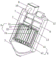
FIG. 2 is a schematic sectional view of the inside of the structure of the present invention;
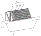
FIG. 3 is a schematic cross-sectional view of the second dust collector of the present invention;
fig. 4 is the inside schematic view of the structure purifying box of the utility model.
In the figure: 1 circular ring plate, 2 purification barrels, 3 conical ash buckets, 4 first dust removal devices, 41 dust removal cloth bags, 42 filter screens, 5 first cleaning devices, 51 mounting frames, 52 motors, 53 rotating plates, 54 brush bristles, 6 second dust removal devices, 61 arc plates, 62 negative plates, 63 positive plates, 7 second cleaning devices, 71 linear motors, 72 steam spraying cavity plates, 73 air pipes, 8 purification boxes, 9 purification structures, 91 clamping grooves, 92HEPA filter screens, 93 leakage hole screen plates, 94 activated carbon pellets, 10 air pipes, 11 exhaust pipes, 12 air pumps, 13 circular ring mounting plates, 14 air extractors, 15 air guide pipes, 16 air inlet pipes, 17 control switch groups, 18 supporting legs and 19 box covers.
Detailed Description
The technical solutions in the embodiments of the present invention will be described clearly and completely with reference to the accompanying drawings in the embodiments of the present invention, and it is obvious that the described embodiments are only some embodiments of the present invention, not all embodiments. Based on the embodiments in the present invention, all other embodiments obtained by a person skilled in the art without creative work belong to the protection scope of the present invention.
Referring to fig. 1-4, the present invention provides a technical solution: an industrial dedusting air purifier comprises a circular plate 1, a first dedusting device 4, a first cleaning device 5, a second dedusting device 6, a second cleaning device 7 and a purifying structure 9;
the circular plate 1: the circular ring plate 1 provides a supporting and mounting platform, the circular ring plate 1 is internally provided with a purifying cylinder 2 in a matching way, the purifying cylinder 2 provides a mounting place, the bottom end opening of the purifying cylinder 2 is provided with a conical ash bucket 3 in a matching way, the conical ash bucket 3 provides storage of filtered dust, the ash outlet at the bottom end of the conical ash bucket 3 is in threaded connection with a seal cover for convenient cleaning, the bottom end of the inner wall of the purifying cylinder 2 is provided with two symmetrically distributed circular ring mounting plates 13 for mounting and supporting, the upper end of the purifying cylinder 2 is respectively provided with a purifying box 8 and an air pump 12, the air pump 12 runs, compressed gas sprays dust, the purifying box 8 provides a purifying place, the air inlet of the purifying box 8 is connected with the air outlet at the upper end of the purifying cylinder 2 through a gas pipe 10, the air outlet of the purifying box 8 is provided with an exhaust pipe 11, the exhaust pipe 11 realizes output of purified gas, the upper end of the purifying, the filter material is convenient to disassemble and replace;
the first dust removing device 4: the first dust removing device 4 is arranged inside the two symmetrically-distributed circular ring mounting plates 13 and is matched with the purifying cylinder 2, the first dust removing device 4 comprises a dust removing cloth bag 41 and a filter screen 42, outer edge plates at the upper end and the lower end of the dust removing cloth bag 41 are respectively in threaded connection with the two symmetrically-distributed circular ring mounting plates 13 through bolts, the dust removing cloth bag 41 is matched with the purifying cylinder 2, the filter screen 42 is matched and arranged inside the lower circular ring mounting plate 13, and efficient adsorption and filtration are carried out through the filter screen 42 and the dust removing cloth bag 41, so that first-layer dust removing operation is realized;
first cleaning device 5: the first cleaning device 5 is arranged on the upper surface of the upper ring mounting plate 13 and is matched with the first dust removal device 4, the first cleaning device 5 comprises a mounting frame 51, a motor 52, a rotating plate 53 and bristles 54, the mounting frame 51 provides mounting support for the motor 52, the mounting frame 51 is matched with the upper surface of the upper ring mounting plate 13, the motor 52 is arranged in a frame ring of the mounting frame 51, the rotating plate 53 is uniformly arranged at the bottom end of an output shaft of the motor 52, the bristles 54 are arranged on the outer side surface of the rotating plate 53, the bristles 54 are matched with the dust removal cloth bag 41, the motor 52 runs, the output shaft rotates to drive the rotating plate 53 to rotate at a certain speed, and then the bristles 54 brush dust on the inner wall surface of the dust removal cloth bag;
the second dust removing device 6: the second dust removing device 6 is arranged at the upper end of the interior of the purification cylinder 2 in a matched mode, the second dust removing device 6 comprises an arc-shaped plate 61, a negative plate 62 and a positive plate 63, the arc-shaped plate 61 is symmetrically arranged at the upper end of the interior of the purification cylinder 2 in a matched mode, the negative plate 62 and the positive plate 63 are respectively arranged on the inner sides of the upper surfaces of the corresponding arc-shaped plates 61 in a matched mode, the negative plate 62 and the positive plate 63 are connected with electricity, then gas passes through the space between the negative plate 62 and the positive plate 63, dust-containing gas is electrically separated when passing through a high-voltage electrostatic field, and after dust particles are charged with negative ions in;
the second cleaning device 7: the second cleaning device 7 is arranged on the upper surface of the upper ring mounting plate 13 and is matched with the second dust removing device 6, the air outlet end of the second cleaning device 7 is connected with the air inlet of the air pump 12, the second cleaning device 7 comprises a linear motor 71, an air spraying cavity plate 72 and an air pipe 73, the linear motor 71 is symmetrically arranged on the upper surface of the upper ring mounting plate 13, two ends of the air spraying cavity plate 72 are respectively and fixedly connected with the inner sides of rotor seats of the two symmetrically distributed linear motors 71, the outer part of the air spraying cavity plate 72 is provided with evenly distributed air ports, the air spraying cavity plate 72 is matched with the positive plate 63, the bottom end of the air pipe 73 is connected with the air inlet of the air spraying cavity plate 72, the top end of the air pipe 73 penetrates through the outer wall of the upper end of the purifying cylinder 2 and is connected with the air inlet of the air pump 12, the air pump 12 operates to convey air through the air pipe 73 and is sprayed out through, blowing off dust adhered to the surface of the positive plate 63, and ensuring the cleanness by reciprocating the linear motor 71;
the purification structure 9: the purifying structure 9 is arranged inside the purifying box 8, the purifying structure 9 comprises a clamping groove 91, an HEPA filter screen 92, a leakage hole screen plate 93 and active carbon balls 94, the leakage hole screen plate 93 plays a role of isolation but does not influence other circulation, the clamping grooves 91 are symmetrically arranged on the inner wall of the box on the left side of the purifying box 8, the clamping blocks on the two sides of the HEPA filter screen 92 are clamped with the clamping groove 91 and are convenient to disassemble and replace, the leakage hole screen plate 93 is arranged in the middle of the purifying box 8 in a matching mode, the active carbon balls 94 are filled in the right side gap of a groove cavity formed by the leakage hole screen plate 93 and the purifying box 8, and the right side gap is adsorbed, filtered and deodorized through the HEPA filter screen 92 and;
wherein: the device also comprises an air extractor 14, an air duct 15, an air inlet pipe 16, a control switch group 17 and supporting legs 18, wherein the air extractor 14 operates, industrial generated gas is input through the air inlet pipe 16 and is guided to the inner bottom end of the purifying cylinder 2 through the air duct 15, the normal operation of each device and elements is adjusted through the control switch group 17, a mounting hole at the bottom of each supporting leg 18 is in threaded connection with a mounting part through a bolt, the mounting and fixing of the device are realized, the air extractor 14 is arranged on a mounting plate of the outer arc surface of the conical ash bucket 3, an air outlet of the air extractor 14 is connected with an air inlet at the bottom of the purifying cylinder 2 through the air duct 15, the air inlet pipe 16 is arranged at the air inlet of the air extractor 14, the control switch group 17 is arranged on the upper surface of the circular ring plate 1, the supporting legs 18 are uniformly arranged on the bottom surface of the circular ring plate 1, the input end of the control switch group 17 is electrically connected, the negative plate 62 and the positive plate 63 are electrically connected to the control switch group 17 through wires.
When in use: the mounting holes at the bottom of the supporting legs 18 are in threaded connection with the mounting positions through bolts, the mounting and fixing of the device are realized, the air inlet pipe 16 is connected with a pipeline for industrially generated gas, the industrially generated gas is input through the air inlet pipe 16 by controlling the switch group 17, the industrially generated gas is guided to the inner bottom end of the purifying cylinder 2 through the air duct 15, the first layer of dust removing operation is realized through efficient adsorption and filtration of the filter screen 42 and the dust removing cloth bag 41, the negative plate 62 and the positive plate 63 are connected with electricity, then the gas passes between the negative plate 62 and the positive plate 63, the dust-containing gas is electrically separated when passing through a high-voltage electrostatic field, the dust particles are charged with negative ions in combination and then discharged and deposited on the surface of the positive plate 63, the second layer of dust filtration is realized, then the gas is output to the purifying box 8 through the gas conveying pipe 10, and is adsorbed, the third layer of dust filtration is realized, the thoroughly filtered gas is discharged to the outside through the exhaust pipe 11, after the dust filter is used for a certain time, more dust particles are adhered to the dust removing cloth bag 41 and the positive plate 63, the operation of the air pump 14 is stopped, part of dust on the positive plate 63 drops into the conical dust hopper 3, the motor 52 operates, the output shaft rotates to drive the rotating plate 53 to rotate at a certain speed, further, the dust on the inner wall surface of the dust removing cloth bag 41 is brushed by the bristles 54 in a rotating way, the air pump 12 operates to convey the gas through the air pipe 73 and is sprayed out through the steam spraying cavity plate 72 and air ports uniformly distributed on the outside to blow off the dust adhered to the surface of the positive plate 63, the linear motor 71 reciprocates to ensure the cleanness, the cleaned dust drops into the conical dust hopper 3, the dust particles in the air are gradually filtered from bottom to top along with the particle size, and the, after the falling process cannot be cleaned, the sealing cover at the bottom end of the conical ash bucket 3 is opened to remove ash, the box cover 19 is periodically opened, and the HEPA filter screen 92 and the activated carbon balls 94 are replaced.
It should be noted that the control switch group 17 disclosed in this embodiment controls the operation of the motor 52, the linear motor 71, the air pump 12 and the air extractor 14 by the methods commonly used in the prior art, and the negative plate 62, the positive plate 63, the motor 52, the linear motor 71, the air pump 12 and the air extractor 14 are all the conventional elements of the air dust removing device in the prior art.
Although embodiments of the present invention have been shown and described, it will be appreciated by those skilled in the art that changes, modifications, substitutions and alterations can be made in these embodiments without departing from the principles and spirit of the invention, the scope of which is defined in the appended claims and their equivalents.
Claims (6)
1. The utility model provides an industrial dust removal air purifier which characterized in that: the device comprises a circular plate (1), a first dust removal device (4), a first cleaning device (5), a second dust removal device (6), a second cleaning device (7) and a purification structure (9);
annular plate (1): a purification cylinder (2) is arranged inside the circular ring plate (1) in a matched mode, a conical ash hopper (3) is arranged at the position of a cylinder opening at the bottom end of the purification cylinder (2) in a matched mode, a sealing cover is connected to an ash outlet at the bottom end of the conical ash hopper (3) in a threaded mode, two circular ring mounting plates (13) which are symmetrically distributed are arranged at the bottom end of the inner wall of the purification cylinder (2), a purification box (8) and an air pump (12) are arranged at the upper end of the purification cylinder (2) respectively, an air inlet of the purification box (8) is connected with an air outlet at the upper end of the purification cylinder (2) through a gas pipe (10), an exhaust pipe (11) is arranged at an air outlet of the purification box (8), the upper end of the purification box (8) is;
first dust removing device (4): the first dust removing devices (4) are arranged inside the two symmetrically distributed circular mounting plates (13) and are matched with the purifying cylinder (2);
first cleaning means (5): the first cleaning device (5) is arranged on the upper surface of the upper ring mounting plate (13) and is matched with the first dust removal device (4);
second dust removal device (6): the second dust removal device (6) is arranged at the upper end of the interior of the purification cylinder (2) in a matching manner;
second cleaning means (7): the second cleaning device (7) is arranged on the upper surface of the upper ring mounting plate (13) and is matched with the second dust removal device (6), and the air outlet end of the second cleaning device (7) is connected with the air inlet of the air pump (12);
purification structure (9): the purification structure (9) is arranged inside the purification box (8);
wherein: still include air extractor (14), air duct (15), intake pipe (16), control switch group (17), landing leg (18), air extractor (14) set up on the mounting panel of circular cone ash bucket (3) extrados, the gas outlet of air extractor (14) passes through air duct (15) and links to each other with the air inlet of purifying a section of thick bamboo (2) bottom, intake pipe (16) set up in the air inlet department of air extractor (14), control switch group (17) set up in the upper surface of ring board (1), landing leg (18) evenly set up in the bottom surface of ring board (1), external power source is connected to the input electricity of control switch group (17), the equal electric connection of input of air pump (12) and air extractor (14) control switch group's (17) output.
2. An industrial dusting air cleaner as claimed in claim 1, wherein: the first dust removal device (4) comprises a dust removal cloth bag (41) and a filter screen (42), wherein the outer edge plates at the upper end and the lower end of the dust removal cloth bag (41) are respectively in threaded connection with two symmetrically-distributed circular mounting plates (13) through bolts, the dust removal cloth bag (41) is matched with the purification cylinder (2), and the filter screen (42) is matched and arranged inside the lower circular mounting plate (13).
3. An industrial dusting air cleaner as claimed in claim 2, wherein: first cleaning device (5) include mounting bracket (51), motor (52), rotor plate (53) and brush hair (54), mounting bracket (51) cooperation sets up in the upper surface of the ring mounting panel (13) on upper strata, and motor (52) set up in the frame intra-annular of mounting bracket (51), and rotor plate (53) evenly set up in the output shaft bottom of motor (52), and brush hair (54) set up on the lateral surface of rotor plate (53), and brush hair (54) and dust removal sack (41) cooperation set up, and the output of control switch group (17) is connected to the input electricity of motor (52).
4. An industrial dusting air cleaner as claimed in claim 1, wherein: the second dust removal device (6) comprises an arc-shaped plate (61), a negative plate (62) and a positive plate (63), the arc-shaped plate (61) is symmetrically arranged at the upper end of the interior of the purification cylinder (2) in a matched mode, the negative plate (62) and the positive plate (63) are respectively arranged on the inner sides of the upper surfaces of the corresponding arc-shaped plates (61) in a matched mode, and the negative plate (62) and the positive plate (63) are electrically connected with the control switch group (17) through wires.
5. An industrial dusting air cleaner as claimed in claim 4, wherein: second cleaning device (7) include linear electric motor (71), spout vapour chamber board (72) and trachea (73), linear electric motor (71) symmetry sets up in ring mounting panel (13) upper surface on upper strata, the both ends of spouting vapour chamber board (72) respectively with the inboard fixed connection of linear electric motor (71) rotor seat of two symmetric distributions, the outside of spouting vapour chamber board (72) is equipped with evenly distributed's gas port, spout vapour chamber board (72) and set up with positive plate (63) cooperation, the bottom of trachea (73) links to each other with the air inlet of spouting vapour chamber board (72), the top of trachea (73) is run through the upper end outer wall of a purification section of thick bamboo (2) and is linked to each other with the air inlet of air pump (12), the output of control switch group (17) is connected to the input electricity of linear electric motor (71).
6. An industrial dusting air cleaner as claimed in claim 1, wherein: purification structure (9) include draw-in groove (91), HEPA filter screen (92), small opening mesh board (93) and active carbon ball (94), draw-in groove (91) symmetry sets up on the left incasement wall of purifying box (8), the fixture block and draw-in groove (91) joint of HEPA filter screen (92) both sides, and small opening mesh board (93) cooperation sets up in the middle part of purifying box (8), and active carbon ball (94) are filled in small opening mesh board (93) and purifying box (8) and are constituteed the right side clearance department in cell chamber.
Priority Applications (1)
| Application Number | Priority Date | Filing Date | Title |
|---|---|---|---|
| CN201921467359.4U CN211098180U (en) | 2019-09-05 | 2019-09-05 | Industrial dust removal air purifier |
Applications Claiming Priority (1)
| Application Number | Priority Date | Filing Date | Title |
|---|---|---|---|
| CN201921467359.4U CN211098180U (en) | 2019-09-05 | 2019-09-05 | Industrial dust removal air purifier |
Publications (1)
| Publication Number | Publication Date |
|---|---|
| CN211098180U true CN211098180U (en) | 2020-07-28 |
Family
ID=71689593
Family Applications (1)
| Application Number | Title | Priority Date | Filing Date |
|---|---|---|---|
| CN201921467359.4U Expired - Fee Related CN211098180U (en) | 2019-09-05 | 2019-09-05 | Industrial dust removal air purifier |
Country Status (1)
| Country | Link |
|---|---|
| CN (1) | CN211098180U (en) |
Cited By (1)
| Publication number | Priority date | Publication date | Assignee | Title |
|---|---|---|---|---|
| CN112316577A (en) * | 2020-10-20 | 2021-02-05 | 嘉兴玖阳环保设备有限公司 | Powder dust remover |
-
2019
- 2019-09-05 CN CN201921467359.4U patent/CN211098180U/en not_active Expired - Fee Related
Cited By (1)
| Publication number | Priority date | Publication date | Assignee | Title |
|---|---|---|---|---|
| CN112316577A (en) * | 2020-10-20 | 2021-02-05 | 嘉兴玖阳环保设备有限公司 | Powder dust remover |
Similar Documents
| Publication | Publication Date | Title |
|---|---|---|
| CN208711287U (en) | A kind of purification device of dedusting strainer | |
| CN210699266U (en) | Industrial filtration dust collecting equipment | |
| CN112999808A (en) | Combined dust removing equipment | |
| CN211098180U (en) | Industrial dust removal air purifier | |
| CN211476167U (en) | Indoor air pollutant purification device | |
| CN107149982A (en) | A kind of lateral bipolar electric-bag complex dust collector | |
| CN210473446U (en) | Novel industrial dust removal device | |
| CN111871610A (en) | Vertical electrostatic fabric filter | |
| CN108636040B (en) | Industrial dust removal equipment | |
| CN208824169U (en) | A kind of high-efficient energy-saving environment friendly cleaner | |
| CN211187042U (en) | Dust collector dust barrel with dust processing function | |
| CN112275049B (en) | Detachable waste gas treatment environmental protection equipment | |
| CN211051708U (en) | Electric dust remover | |
| CN210121560U (en) | Spore powder production purification and dust removal device | |
| CN112915676A (en) | Pulse dust collector with fold filter cylinder | |
| CN207831582U (en) | A kind of continuous dust dust-collecting air purifier | |
| CN215310946U (en) | Dust remover with automatic cleaning function | |
| CN206304905U (en) | A kind of electrostatic precipitator with automatic clearing function | |
| CN211159126U (en) | Assembled dust collecting equipment with filtering capability | |
| CN210229524U (en) | Workshop dust disposal environmental protection system | |
| CN220759568U (en) | Dust trapping device for producing negative electrode material | |
| CN219764855U (en) | Waste gas filtering device | |
| CN108654837A (en) | A kind of efficient composite dust pelletizing system | |
| CN215027291U (en) | Dust remover for pulverized coal bunker | |
| CN212881506U (en) | Pulse dust collector |
Legal Events
| Date | Code | Title | Description |
|---|---|---|---|
| GR01 | Patent grant | ||
| GR01 | Patent grant | ||
| CF01 | Termination of patent right due to non-payment of annual fee |
Granted publication date: 20200728 Termination date: 20210905 |
|
| CF01 | Termination of patent right due to non-payment of annual fee |