CN211095453U - Medical bed convenient to move - Google Patents
Medical bed convenient to move Download PDFInfo
- Publication number
- CN211095453U CN211095453U CN201920759340.0U CN201920759340U CN211095453U CN 211095453 U CN211095453 U CN 211095453U CN 201920759340 U CN201920759340 U CN 201920759340U CN 211095453 U CN211095453 U CN 211095453U
- Authority
- CN
- China
- Prior art keywords
- bed
- connecting plate
- fixedly connected
- bed body
- medical
- Prior art date
- Legal status (The legal status is an assumption and is not a legal conclusion. Google has not performed a legal analysis and makes no representation as to the accuracy of the status listed.)
- Expired - Fee Related
Links
Images

Landscapes
- Invalid Beds And Related Equipment (AREA)
Abstract
The utility model discloses a medical bed convenient to remove relates to medical instrument technical field, and it includes the bed body, three slide rail has been seted up to the upper surface of the bed body, sliding connection has the slider in the slide rail, the upper surface of slider is connected with the lower fixed surface of bed board, the upper surface of bed board is provided with the mattress, the equal fixedly connected with fixed block of the left and right sides face of bed board. This medical bed convenient to remove, through setting up the bed body, the bed board, the fixture block, the connecting plate, the draw-in groove, the slider, bearing and slide rail, release the connecting plate, make fixture block and fixed block contact, on the same principle, medical personnel stimulate right side connecting plate right, make eight fixture blocks break away from eight draw-in grooves respectively, medical personnel promote the bed board forward, make three slider break away from three slide rail respectively, can move the bed board to the operation bed, do not need medical personnel to lift the patient and shift, be difficult to cause the secondary injury to the patient, medical personnel's working strength has been alleviateed.
Description
Technical Field
The utility model relates to the technical field of medical equipment, in particular to a medical bed convenient to move.
Background
In clinical care, the patient needs to move the body of the patient from a hospital bed to an operation trolley before operation due to disability, unconsciousness, paralysis and other diseases, and also needs to move the body of the patient from the operation trolley back to the hospital bed after operation, in the process of transferring the patient, most of the patients need to be lifted up by medical care personnel for transferring, and the patient feels uncomfortable and easily suffers from secondary injury due to serious diseases of some patients, so that the patient's diseases further worsen, and the working strength of the medical care personnel is increased.
SUMMERY OF THE UTILITY MODEL
Technical problem to be solved
The utility model provides a not enough to prior art, the utility model provides a medical bed convenient to remove has solved and still will move back its health to the sick bed from the operation car after the operation, at the in-process that shifts the patient, at present most need medical personnel to lift up the patient and shift, lift up the in-process of putting down, because some patients are more serious, make the patient feel very uncomfortable, cause secondary damage easily, the patient's of further worsening state of an illness has still increased medical personnel's working strength's problem.
(II) technical scheme
In order to achieve the above purpose, the utility model adopts the technical proposal that: the utility model provides a medical bed convenient to remove, includes the bed body, three slide rail has been seted up to the upper surface of the bed body, sliding connection has the slider in the slide rail, the upper surface of slider and the lower fixed surface of bed board are connected, the upper surface of bed board is provided with the mattress, the equal fixedly connected with fixed block of the left and right sides face of bed board, the left surface of fixed block is seted up flutedly.
The right flank of recess inner wall passes through telescoping device and rotary device's right-hand member fixed connection, the rotary device joint is at the right flank of connecting plate, four fixture blocks of right flank fixed connection of connecting plate, the fixture block is located the draw-in groove, the draw-in groove is seted up at the left surface of the bed body, the equal fixedly connected with second telescopic link in four corners department of bed body lower surface.
The bottom of second telescopic link is provided with the universal wheel, and the front and the back of two second telescopic links on left side and two second telescopic links on right side respectively with the back and the front fixed connection of two backup pads, the upper surface of backup pad passes through electric putter and the lower fixed surface of the bed body to be connected.
Preferably, the upper surface of bed board is fixedly connected with two guardrails, the left side of connecting plate is provided with the handle, and the shape of handle sets up to semi-circular.
Preferably, the telescopic device comprises a first telescopic rod, a spring is sleeved on the outer surface of the first telescopic rod, the left ends of the first telescopic rod and the spring are fixedly connected with the right end of the rotating device, and the right ends of the first telescopic rod and the spring are fixedly connected with the right side face of the inner wall of the groove.
Preferably, rotary device includes the bearing, the bearing joint is at the right flank of connecting plate, the pivot has been cup jointed in the bearing, the right-hand member of pivot and the left end fixed connection of first telescopic link and spring.
Preferably, the front surface of the bed body is fixedly connected with the back surface of the power supply, and the front surface of the power supply is fixedly connected with the back surface of the switch.
Preferably, the output end of the power supply is electrically connected with the input end of the switch through a wire, and the output end of the switch is electrically connected with the input end of the electric push rod through a wire.
(III) advantageous effects
The beneficial effects of the utility model reside in that:
1. the medical bed convenient to move is characterized in that the bed body, the bed plate, the clamping blocks, the connecting plate, the first telescopic rod, the clamping grooves, the sliding blocks, the bearing and the sliding rails are arranged, when a patient needs to be transferred, the operation bed is aligned with the back surface of the bed body, medical staff pulls the left connecting plate leftwards to enable the connecting plate to drive the four clamping blocks to move leftwards, when the four clamping blocks are respectively separated from the four clamping grooves, the medical staff rotates the connecting plate to enable the four clamping blocks and the four clamping grooves to be in a staggered state, then releases the connecting plate to enable the clamping blocks to be in contact with the fixing blocks, and in the same way, the medical staff pulls the right connecting plate rightwards to enable the eight clamping blocks to be respectively separated from the eight clamping grooves, pushes the bed plate forwards to enable the three sliding blocks to be separated from the three sliding rails respectively, the working strength of medical staff is reduced.
2. This medical bed convenient to remove, through setting up first telescopic link, a spring, the connecting plate, the fixture block, the draw-in groove, the slider, a slide rail, bed board and the bed body, when needs shift the patient to the bed body on, medical personnel promote the bed board, make two sliders be located three slide rail respectively, the bed board moves behind suitable position, medical personnel stimulate left side connecting plate and rotate left, aim at four draw-in grooves respectively with four fixture blocks, slowly release the connecting plate, make the spring shrink drive first telescopic link and connecting plate move right, make the connecting plate drive four fixture blocks and block respectively in four draw-in grooves, the same principle, medical personnel stimulate right side connecting plate, make eight fixture block respectively block go into eight draw-in grooves, can install the bed board, it is very convenient to operate, be convenient for medical personnel shift the patient from the operation table to the.
3. This medical bed convenient to remove, through setting up the second telescopic link, the universal wheel, electric putter, the bed body, guardrail and bearing, when the height of the bed body is adjusted to needs, control two electric putter work, make two electric putter extensions drive same bed body rebound, make the bed body can satisfy not operation table of co-altitude and shift the patient, because of being provided with the universal wheel, when the bed body is removed to needs, medical personnel can promote the bed body and remove, make things convenient for medical personnel to shift the position to the bed body, because of being provided with the second telescopic link, the bed body can not rock and more stable when electric putter extension or shorten the drive bed board and reciprocate, because of being provided with the guardrail, make the difficult bed board that falls of patient, because of being provided with the bearing, make medical personnel can not rock and more stable when rotating the connecting.
Drawings
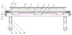
Fig. 1 is a schematic front view of a cross-sectional structure of the present invention;
FIG. 2 is a left side view of the bed plate of the present invention;
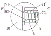
fig. 3 is an enlarged schematic structural diagram of a position a of the present invention.
In the figure: the bed comprises a bed body 1, a sliding rail 2, a sliding block 3, a bed board 4, a mattress 5, a fixed block 6, a telescopic device 7, a spring 71, a first telescopic rod 72, a groove 8, a rotating device 9, a bearing 91, a rotating shaft 92, a connecting plate 10, a clamping block 11, a clamping groove 12, a second telescopic rod 13, a universal wheel 14, a supporting plate 15, an electric push rod 16, a power supply 17, a switch 18 and a guardrail 19.
Detailed Description
The technical solutions in the embodiments of the present invention will be described clearly and completely with reference to the accompanying drawings in the embodiments of the present invention, and it is obvious that the described embodiments are only some embodiments of the present invention, not all embodiments. Based on the embodiments in the present invention, all other embodiments obtained by a person skilled in the art without creative work belong to the protection scope of the present invention.
As shown in fig. 1-3, the utility model provides a technical solution: a medical bed convenient to move comprises a bed body 1, the upper surface of the bed body 1 is provided with three slide rails 2, the slide rails 2 are connected with a slide block 3 in a sliding manner, the upper surface of the slide block 3 is fixedly connected with the lower surface of a bed board 4, the front surface of the bed body 1 is fixedly connected with the back surface of a power supply 17, the front surface of the power supply 17 is fixedly connected with the back surface of a switch 18, the output end of the power supply 17 is electrically connected with the input end of the switch 18 through a wire, the output end of the switch 18 is electrically connected with the input end of an electric push rod 16 through a wire, the power supply 17 can supply power to the electric push rod 16 by setting the power supply 17, so that the electric push rod 16 can normally work, medical personnel can more conveniently control the electric push rod 16 to work by setting the switch 18, the upper surface of the bed, because of being provided with guardrail 19 for the difficult bed board 4 that falls of patient, the upper surface of bed board 4 is provided with mattress 5, and the equal fixedly connected with fixed block 6 of the left and right sides face of bed board 4, the left surface of fixed block 6 is seted up flutedly 8.
The right side surface of the inner wall of the groove 8 is fixedly connected with the right end of the rotating device 9 through the expansion device 7, the rotating device 9 is connected with the right side surface of the connecting plate 10 in a clamping manner, the expansion device 7 comprises a first expansion link 72, the outer surface of the first expansion link 72 is sleeved with a spring 71, the left ends of the first expansion link 72 and the spring 71 are fixedly connected with the right end of the rotating device 9, the right ends of the first expansion link 72 and the spring 71 are fixedly connected with the right side surface of the inner wall of the groove 8, the spring 71 is arranged, so that the spring 71 is contracted to drive the first expansion link 72 and the connecting plate 10 to move rightwards, the connecting plate 10 drives the four clamping blocks 11 to be respectively clamped into the four clamping grooves 12, and similarly, medical staff pulls the right connecting plate 10 to enable the eight clamping blocks 11 to be respectively clamped into the eight clamping grooves 12, the bed plate 4 can be installed, the, pivot 92 has been cup jointed in bearing 91, the right-hand member of pivot 92 and the left end fixed connection of first telescopic link 72 and spring 71, because of being provided with bearing 91, make medical personnel can not rock and more stable when rotating connecting plate 10, four fixture blocks 11 of right flank fixedly connected with of connecting plate 10, because of being provided with universal wheel 14, when needs removal bed body 1, medical personnel can promote bed body 1 and remove, make things convenient for medical personnel to carry out the shift position to bed body 1, fixture block 11 is located draw-in groove 12, draw-in groove 12 is seted up at bed body 1's left surface, the equal fixedly connected with second telescopic link 13 in four corners department of bed body 1 lower surface.
The bottom of second telescopic link 13 is provided with universal wheel 14, because of being provided with second telescopic link 13, bed body 1 can not rock and more stable when electric putter 16 extension or shorten the drive bed board 4 and reciprocate, and the front and the back of two second telescopic links 13 on left side and two second telescopic links 13 on right side respectively with the back and the front fixed connection of two backup pads 15, through setting up electric putter 16, when the height of bed body 1 is adjusted to needs, control two electric putter 16 work, make two electric putter 16 extensions drive same bed body 1 rebound, make bed body 1 can satisfy not co-altitude's operation table and shift the patient, electric putter 16 is passed through with bed body 1's lower fixed surface and is connected to the upper surface of backup pad 15.
The utility model discloses an operating procedure does:
s1, when a patient needs to be transferred, the operation bed is aligned with the back of the bed body 1, medical staff pulls the left connecting plate 10 leftwards to enable the connecting plate 10 to drive the four clamping blocks 11 to move leftwards, after the four clamping blocks 11 are respectively separated from the four clamping grooves 12, the medical staff rotates the connecting plate 10 to enable the four clamping blocks 11 and the four clamping grooves 12 to be in a staggered state, then releases the connecting plate 10 to enable the clamping blocks 11 to be in contact with the fixed blocks 6, and similarly, the medical staff pulls the right connecting plate 10 rightwards to enable the eight clamping blocks 11 to be separated from the eight clamping grooves 12 respectively, pushes the bed plate 4 forwards to enable the three sliding blocks 3 to be separated from the three sliding rails 2 respectively, and then can move the bed;
s2, when a patient needs to be transferred to the bed body 1, a medical worker pushes the bed plate 4 to enable the two sliding blocks 3 to be located in the three sliding rails 2 respectively, after the bed plate 4 moves to a proper position, the medical worker pulls the left connecting plate 10 to rotate, the four clamping blocks 11 are aligned to the four clamping grooves 12 respectively, the connecting plate 10 is released slowly, the spring 71 contracts to drive the first telescopic rod 72 and the connecting plate 10 to move rightwards, the connecting plate 10 drives the four clamping blocks 11 to be clamped into the four clamping grooves 12 respectively, and similarly, the medical worker pulls the right connecting plate 10 to enable the eight clamping blocks 11 to be clamped into the eight clamping grooves 12 respectively, and then the bed plate 4 can be installed;
s3, when the height of the bed body 1 needs to be adjusted, the two electric push rods 16 are controlled to work, so that the two electric push rods 16 extend to drive the same bed body 1 to move upwards, the bed body 1 can meet the requirements of patients transferring through operation beds with different heights, and due to the fact that the universal wheels 14 are arranged, when the bed body 1 needs to be moved, medical staff can push the bed body 1 to move.
The above-mentioned embodiments further describe the objects, technical solutions and advantages of the present invention in detail, it should be understood that the above description is only the embodiments of the present invention, and is not intended to limit the present invention, and any modifications, equivalent substitutions, improvements and the like made within the spirit and principle of the present invention should be included in the scope of the present invention.
Claims (6)
1. The utility model provides a medical bed convenient to remove, includes bed body (1), its characterized in that: the bed is characterized in that three sliding rails (2) are arranged on the upper surface of the bed body (1), a sliding block (3) is connected in the sliding rails (2) in a sliding mode, the upper surface of the sliding block (3) is fixedly connected with the lower surface of the bed plate (4), a mattress (5) is arranged on the upper surface of the bed plate (4), fixed blocks (6) are fixedly connected to the left side surface and the right side surface of the bed plate (4), and a groove (8) is formed in the left side surface of each fixed block (6);
the right side surface of the inner wall of the groove (8) is fixedly connected with the right end of a rotating device (9) through a telescopic device (7), the rotating device (9) is clamped on the right side surface of a connecting plate (10), the right side surface of the connecting plate (10) is fixedly connected with four clamping blocks (11), the clamping blocks (11) are located in clamping grooves (12), the clamping grooves (12) are formed in the left side surface of the bed body (1), and the four corners of the lower surface of the bed body (1) are fixedly connected with second telescopic rods (13);
the bottom of second telescopic link (13) is provided with universal wheel (14), and the front and the back of two second telescopic links (13) on the left side and two second telescopic links (13) on the right side respectively with the back and the front fixed connection of two backup pads (15), the upper surface of backup pad (15) passes through electric putter (16) and is connected with the lower fixed surface of the bed body (1).
2. A portable hospital bed according to claim 1, wherein: the upper surface of bed board (4) is fixedly connected with two guardrails (19), the left side of connecting plate (10) is provided with the handle, and the shape of handle sets up to semi-circular.
3. A portable hospital bed according to claim 1, wherein: telescoping device (7) include first telescopic link (72), spring (71) have been cup jointed to the surface of first telescopic link (72), the left end of first telescopic link (72) and spring (71) all with the right-hand member fixed connection of rotary device (9), the right-hand member of first telescopic link (72) and spring (71) all with the right flank fixed connection of recess (8) inner wall.
4. A portable hospital bed according to claim 3, wherein: rotating device (9) include bearing (91), bearing (91) joint is at the right flank of connecting plate (10), cup jointed pivot (92) in bearing (91), the right-hand member of pivot (92) and the left end fixed connection of first telescopic link (72) and spring (71).
5. A portable hospital bed according to claim 1, wherein: the front surface of the bed body (1) is fixedly connected with the back surface of a power supply (17), and the front surface of the power supply (17) is fixedly connected with the back surface of a switch (18).
6. A portable hospital bed according to claim 5, wherein: the output end of the power supply (17) is electrically connected with the input end of the switch (18) through a lead, and the output end of the switch (18) is electrically connected with the input end of the electric push rod (16) through a lead.
Priority Applications (1)
| Application Number | Priority Date | Filing Date | Title |
|---|---|---|---|
| CN201920759340.0U CN211095453U (en) | 2019-05-24 | 2019-05-24 | Medical bed convenient to move |
Applications Claiming Priority (1)
| Application Number | Priority Date | Filing Date | Title |
|---|---|---|---|
| CN201920759340.0U CN211095453U (en) | 2019-05-24 | 2019-05-24 | Medical bed convenient to move |
Publications (1)
| Publication Number | Publication Date |
|---|---|
| CN211095453U true CN211095453U (en) | 2020-07-28 |
Family
ID=71711393
Family Applications (1)
| Application Number | Title | Priority Date | Filing Date |
|---|---|---|---|
| CN201920759340.0U Expired - Fee Related CN211095453U (en) | 2019-05-24 | 2019-05-24 | Medical bed convenient to move |
Country Status (1)
| Country | Link |
|---|---|
| CN (1) | CN211095453U (en) |
Cited By (2)
| Publication number | Priority date | Publication date | Assignee | Title |
|---|---|---|---|---|
| CN113663181A (en) * | 2021-08-26 | 2021-11-19 | 青岛市市立医院(青岛市临床医学研究所、青岛市医学影像中心) | Positioner is used in clinical tumour chemotherapy |
| CN114129352A (en) * | 2021-12-16 | 2022-03-04 | 嘉兴市正群医疗器械有限公司 | Medical patient transfer mattress |
-
2019
- 2019-05-24 CN CN201920759340.0U patent/CN211095453U/en not_active Expired - Fee Related
Cited By (2)
| Publication number | Priority date | Publication date | Assignee | Title |
|---|---|---|---|---|
| CN113663181A (en) * | 2021-08-26 | 2021-11-19 | 青岛市市立医院(青岛市临床医学研究所、青岛市医学影像中心) | Positioner is used in clinical tumour chemotherapy |
| CN114129352A (en) * | 2021-12-16 | 2022-03-04 | 嘉兴市正群医疗器械有限公司 | Medical patient transfer mattress |
Similar Documents
| Publication | Publication Date | Title |
|---|---|---|
| CN211095453U (en) | Medical bed convenient to move | |
| CN106726235A (en) | A kind of care bed for facilitating patient to use | |
| CN209809013U (en) | Auxiliary acupuncture table combining traditional Chinese medicine and western medicine | |
| CN105250093B (en) | A kind of automation rehabilitation care bed driven by linear motor | |
| CN213373094U (en) | Patient transfer device | |
| CN211750639U (en) | Anesthesia patient is with standing up auxiliary device | |
| CN211584113U (en) | Internal medicine disease nursing device | |
| CN101966115A (en) | Treatment table | |
| CN216021827U (en) | Deformable bed surface structure of intelligent nursing robot | |
| CN214596255U (en) | Nursing bed body elevation structure | |
| CN215689360U (en) | Auxiliary moving device for emergency treatment | |
| CN205163458U (en) | Novel nursing bed | |
| CN211188025U (en) | Operation bed for local anesthesia inguinal hernia repair operation | |
| CN210932286U (en) | Patient transfer bed | |
| CN208096911U (en) | A kind of dual-purpose type Wheel-chair type bed | |
| CN214415052U (en) | Transfer bed convenient for patient transfer | |
| CN216168397U (en) | Surgical clinical nursing is with supplementary device of getting up | |
| CN212879898U (en) | Nursing bed for neurology | |
| CN220293750U (en) | Portable emergent intensive care unit of first aid | |
| CN104921884A (en) | Sickbed capable of assisting postoperative patient in changing positions sideways | |
| CN220109981U (en) | Adjustable medical multifunctional bed | |
| CN215689359U (en) | Displacement machine | |
| CN218391479U (en) | Severe patient is with transporting stretcher | |
| CN221636415U (en) | Lifting back moving type nursing bed | |
| CN211934659U (en) | Intelligent sickbed for ICU |
Legal Events
| Date | Code | Title | Description |
|---|---|---|---|
| GR01 | Patent grant | ||
| GR01 | Patent grant | ||
| CF01 | Termination of patent right due to non-payment of annual fee |
Granted publication date: 20200728 |
|
| CF01 | Termination of patent right due to non-payment of annual fee |