CN211079211U - Electrode off-line type automatic lengthening device - Google Patents
Electrode off-line type automatic lengthening device Download PDFInfo
- Publication number
- CN211079211U CN211079211U CN201921981701.2U CN201921981701U CN211079211U CN 211079211 U CN211079211 U CN 211079211U CN 201921981701 U CN201921981701 U CN 201921981701U CN 211079211 U CN211079211 U CN 211079211U
- Authority
- CN
- China
- Prior art keywords
- electrode
- wheel
- base
- support
- transmission
- Prior art date
- Legal status (The legal status is an assumption and is not a legal conclusion. Google has not performed a legal analysis and makes no representation as to the accuracy of the status listed.)
- Active
Links
Images


Abstract
The utility model provides an electrode off-line automatic extension device belongs to the off-line and smelts auxiliary assembly, and the device includes base, guide frame, drive arrangement, presss from both sides tight rotary device and compensation arrangement etc, the utility model provides a novel device can utilize the guide frame quick installation extension electrode at top, can high-efficiently, reliably press from both sides tight and drive new electrode rotation in order to realize new, threaded connection between the old electrode based on novel tight rotary device that presss from both sides, and simultaneously, this scheme has still designed bottom fixing device and has been used for pressing from both sides tight old electrode, has further increased the practicality of equipment, and the device's popularization can reduce off-line and smelt electrode extension's intensity of labour and potential safety hazard in the auxiliary assembly.
Description
Technical Field
The utility model belongs to off-line smelting auxiliary equipment, in particular to an electrode off-line automatic lengthening device.
Background
The submerged arc furnace is also called electric arc furnace or resistance furnace. It is mainly used for reducing and smelting raw materials such as ore, carbonaceous reducing agent and solvent. The method is mainly used for producing ferrosilicon, ferromanganese, ferrochromium, ferrotungsten, silicomanganese and other ferroalloys, and is an important industrial raw material in the metallurgical industry and a chemical raw material such as calcium carbide and the like. It features use of carbon or magnesium refractory as furnace lining and self-culturing electrode. The electrode is inserted into the furnace charge to carry out submerged arc operation, the energy and current of the electric arc are utilized to pass through the furnace charge, the energy is generated due to the resistance of the furnace charge to smelt metal, the charging is carried out sequentially, the iron slag is discharged intermittently, and the continuous operation is carried out.
With the use of the submerged arc furnace, the electrode is continuously consumed, and the electrode needs to be lengthened. The submerged arc furnace equipped at home and abroad at present is manually operated when the electrode is lengthened and screwed, and the operation steps are that workers climb to the top of a submerged arc furnace holder after the submerged arc furnace is powered off and stopped, the electrode is hung on the furnace top by a crown block, the workers hold the electrode by hands to carry out thread butt joint, and then several workers manually screw the electrode by special wrenches. The mode of manually stopping and lengthening the electrode leads the operation rate of the submerged arc furnace to be reduced, and the productivity of the submerged arc furnace is influenced. When the electrodes of some submerged arc furnaces needing continuous operation are lengthened, the reduction atmosphere in the furnaces is seriously damaged due to power failure and furnace shutdown, so that the submerged arc furnace has high loss, low smelting speed and increased product power consumption. And the operation environment of the top of the holder of the submerged arc furnace, which belongs to the high-temperature area of the submerged arc furnace, is very bad, and the labor intensity of operators climbing to the furnace top for electrode extension is high and certain dangers are also accompanied.
SUMMERY OF THE UTILITY MODEL
The utility model provides a novel device can utilize the leading truck of top to install extension electrode fast, can be high-efficient, reliable clamp tightly and drive new electrode rotation in order to realize the threaded connection between new, the old electrode based on novel tight rotary device that presss from both sides, simultaneously, this scheme has still designed bottom fixing device and has been used for pressing from both sides tight old electrode, has further increased the practicality of equipment, and the device's popularization can reduce off-line smelting auxiliary assembly in electrode extension's intensity of labour and potential safety hazard.
In order to achieve the above object, the embodiments of the present invention adopt the following technical solutions:
the utility model provides an electrode off-line automatic extension device includes base, guide frame, drive arrangement, presss from both sides tight rotary device, compensation arrangement and fixing device, wherein: the base is used as a bearing main body and comprises a supporting plate, a guide cavity and a connecting flange, the supporting plate is arranged at the top of the guide cavity, and the connecting flange is arranged at the bottom of the guide cavity and used for connecting a submerged arc furnace device; the guide frame is arranged at the top of the support plate and used for guiding a new electrode into the base, the guide frame comprises a first support and a second support which are arranged oppositely, an upper guide wheel and a lower guide wheel are arranged at the top of the first support, a rotary guide wheel is arranged at the top of the second support, and a space for the new electrode to pass through is formed between the upper guide wheel and the lower guide wheel and between the rotary guide wheel and the rotary guide wheel; the driving device is arranged on one side of the base and drives the clamping and rotating device to work through a gear; the tight rotating device is used for clamping and driving the new electrode to rotate so as to realize threaded connection between the new electrode and the old electrode, the tight rotating device is arranged at the top of the compensating device through a bearing, and the compensating device is arranged in the supporting plate; fixing device is used for pressing from both sides tight old electrode and includes actuating cylinder, hydro-cylinder seat, presss from both sides tight rocking arm and rocking arm base, actuating cylinder's bottom articulates on the hydro-cylinder seat, press from both sides tight rocking arm and articulate on the rocking arm base, the telescopic link of actuating cylinder is connected to the one end of pressing from both sides tight rocking arm, presss from both sides tight rocking arm and realizes the swing motion under actuating cylinder's drive, and the other end that presss from both sides tight rocking arm can stretch into guide intracavity portion and fix old electrode.
Preferably, the upper and lower guide wheels comprise a first conical wheel and a second conical wheel which are symmetrically arranged, and the rotary guide wheel comprises a first round wheel and a second round wheel which are symmetrically arranged, wherein: the rotation centers of the first conical wheel and the second conical wheel are vertical to the center of the new electrode, and the side surfaces of the first conical wheel and the second conical wheel are used for leading the new electrode to move up and down; the rotation centers of the first round wheel and the second round wheel are parallel to the center of the new electrode, and the side surfaces of the first round wheel and the second round wheel are used for guiding the screwing action of the old electrode.
Preferably, the bottom of first support and second support all is provided with pulley adjusting device, pulley adjusting device includes fixed screw, slider, spout, first adjusting bolt and second adjusting bolt, wherein: the bottom of first support and second support is passed through fixed screw and is installed on the slider, with the spout setting that the slider corresponds is in the backup pad, and first adjusting bolt and second adjusting bolt set up respectively in the both sides of slider, can drive the slider and remove in order to realize the distance between first support and the second support in the spout through the extension length of adjusting first adjusting bolt and second adjusting bolt.
Preferably, the fixing device further comprises a rocker arm sliding block and a base adjusting device, the rocker arm base is installed on the rocker arm sliding block, the base adjusting device is arranged on two sides of the rocker arm sliding block, and the position of the rocker arm base can be adjusted through the base adjusting device so as to change the action range of the clamping rocker arm.
Preferably, the compensating device comprises a bottom plate, a lifting plate, a guide cavity, a spring, a support rod and a buffer washer, wherein: the bottom plate is arranged on the supporting plate, the guide cavity is arranged at the bottom of the lifting plate, the opening of the guide cavity faces downwards, the bottom of the supporting rod is fixed on the bottom plate, the top of the supporting rod is arranged in the guide cavity, the spring is arranged in a space formed by the inner wall of the guide cavity and the top of the supporting rod, and the cushion pad is sleeved at the bottom of the supporting rod.
Preferably, the driving device comprises a motor, a speed reducer installed at the output end of the motor, and a driving gear installed at the output end of the speed reducer, and the output shaft of the speed reducer is further provided with a torque sensor.
Preferably, the clamping rotation device comprises an outer ring, a transmission arm and an inner ring, wherein: a gear ring is arranged outside the outer ring and is in matched transmission with the driving gear, and a plurality of transmission notches are formed in the outer ring; the inner ring and the outer ring are arranged concentrically, and a tightening notch is arranged at the position of the inner ring close to the transmission notch; the rotatable installation of driving arm is on step up the breach, the driving arm comprises transmission end, mounting hole and step up the end, the transmission end sets up inside the transmission breach, step up the end and can outwards stretch out around the inside round pin axle of mounting hole under stirring of transmission end in order to step up fixed inside electrode.
The utility model discloses an automatic extension device of electrode off-line has following beneficial effect:
(1) this scheme cooperation overhead traveling crane or crane can realize the butt joint of new, old electrode under alone's operation, very big reduction intensity of labour and potential safety hazard, guide frame and the tight rotary device of clamp in the scheme can be on the one hand quick guide electrode get into the base in, get into the top of old electrode under the guide in guide chamber, on the other hand can be under the drive of the tight rotary device of clamp, reliable rotatory threaded connection who realizes new, old electrode.
(2) The leading truck that has adopted in this scheme is provided with leading wheel and rotatory leading wheel from top to bottom simultaneously to realize the quick guide of electrode, the distance between the leading truck is adjustable to be applicable to the electrode of different diameters. Meanwhile, the scheme is provided with the compensation device, so that the impact force generated in the fixing, rotating and butting processes of the electrodes can be greatly buffered. The fixing device in the scheme has a simple and practical structure and can be suitable for fixing the old electrodes with different diameters.
Drawings
Fig. 1 is a schematic view of the overall structure of the present invention;
fig. 2 is a top view of the present invention;
FIG. 3 is a schematic structural view of the pulley adjusting device of the present invention;
FIG. 4 is a schematic view of the chute structure of the present invention;
FIG. 5 is a schematic structural diagram of the compensating device of the present invention;
FIG. 6 is a schematic view of the structure of the middle fixing device of the present invention;
fig. 7 is a schematic structural view of the driving device of the present invention;
fig. 8 is a schematic structural view of a clamping and rotating device of the present invention;
fig. 9 is a partially enlarged view of fig. 8.
In the figure, 1-base, 101-supporting plate, 102-connecting flange, 103-guiding cavity, 2-guiding frame, 201-first support, 202-second support, 203-upper and lower guide wheels, 204-rotating guide wheel, 205-pulley adjusting device, 2031-first cone wheel, 2032-second cone wheel, 2041-first circular wheel, 2042-second circular wheel, 2051-fixing screw, 2052-sliding block, 2053-sliding groove, 2054-first adjusting bolt, 2055-second adjusting bolt, 3-driving device, 301-motor, 302-reducer, 303-driving gear, 304-torque sensor, 4-clamping rotating device, 401-outer ring, 402-driving arm, 403-inner ring, 4011-gear ring, 4012-transmission notch, 4021-transmission end, 4022-mounting hole, 4023-clamping end, 4031-clamping notch, 5-compensation device, 501-bottom plate, 502-lifting plate, 503-guide cavity, 504-spring, 505-support rod, 506-cushion washer, 6-fixing device, 601-driving oil cylinder, 602-oil cylinder seat, 603-clamping rocker arm, 604-rocker arm base, 605-rocker arm sliding block, 606-base adjusting device, 7-new electrode and 8-old electrode.
Detailed Description
In the description of the present invention, it is to be understood that the terms "center", "upper", "lower", "front", "rear", "left", "right", "vertical", "horizontal", "top", "bottom", "inner", "outer", and the like indicate orientations or positional relationships based on those shown in the drawings, and are merely for convenience of description and simplicity of description, and do not indicate or imply that the device or element referred to must have a particular orientation, be constructed and operated in a particular orientation, and therefore, are not to be construed as limiting the present invention. The terms "first", "second" and "first" are used for descriptive purposes only and are not to be construed as indicating or implying relative importance or implicitly indicating the number of technical features indicated. Thus, a feature defined as "first" or "second" may explicitly or implicitly include one or more of that feature. In the description of the present invention, "a plurality" means two or more unless otherwise specified.
The invention is further explained according to the attached drawings:
as shown in fig. 1 and 2, an electrode offline automatic lengthening device includes a base 1, a guide frame 2, a driving device 3, a clamping and rotating device 4, a compensating device 5 and a fixing device 6, wherein the base 1 is used as a bearing main body for installation and fixation of supporting equipment, the guide frame 2 is used for guiding a new electrode 7 to enter the base 1 and to contact with an old electrode 8, the driving device 3 is used for driving the clamping and rotating device 4 to work, the clamping and rotating device 4 can reliably drive the new electrode 7 to rotate, the compensating device 5 is installed at the bottom of the clamping and rotating device 4 and used for electrode butt joint and impact force in the rotating process, and the fixing device 6 is used for fixing the old electrode 8.
In fig. 1, a base 1 is composed of a supporting plate 101, a guide cavity 102 and a connecting flange 103, wherein the supporting plate 101 is installed at the top of the guide cavity 102, and the connecting flange 103 is installed at the bottom of the guide cavity 102 for connecting with a submerged arc furnace device; the guide frame 2 is installed on the top of the support plate 101 and used for guiding the new electrode 7 to enter the base 1, the guide frame 2 comprises a first support 201 and a second support 202 which are arranged oppositely, an upper guide wheel 203 and a lower guide wheel 203 are installed on the top of the first support 201, a rotary guide wheel 204 is installed on the top of the second support 202, and a space for the new electrode 7 to pass through is formed between the upper guide wheel 203 and the lower guide wheel 204, which is shown in fig. 2 specifically.
Specifically, the upper and lower guide wheels 203 comprise a first conical wheel 2031 and a second conical wheel 2032 which are symmetrically arranged, the rotating guide wheel 204 comprises a first round wheel 2041 and a second round wheel 2042 which are symmetrically arranged, the rotating centers of the first conical wheel 2031 and the second conical wheel 2032 are perpendicular to the center of the new electrode 7, and the side surfaces of the first conical wheel 2031 and the second conical wheel 2032 are used for guiding the new electrode 7 to move up and down; the centers of rotation of the first round wheel 2041 and the second round wheel 2042 are parallel to the center of the new electrode 7, and the side surfaces of the first round wheel 2041 and the second round wheel 2042 are used for guiding the screwing action of the old electrode 8.
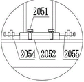
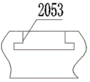
It should be noted that in this embodiment, the distance between the first bracket 201 and the second bracket 202 can be adjusted to adapt to the passage of electrodes with different diameters, pulley adjusting devices 205 are disposed at the bottoms of the first bracket 201 and the second bracket 202, each pulley adjusting device 205 includes a fixing screw 2051, a slider 2052, a sliding slot 2053, a first adjusting bolt 2054 and a second adjusting bolt 2055, the bottoms of the first bracket 201 and the second bracket 202 are mounted on the slider 2052 through the fixing screw 2051, the sliding slot 2053 corresponding to the slider 2052 is disposed on the support plate 101, the first adjusting bolt 2054 and the second adjusting bolt 2055 are disposed at two sides of the slider 2052, and the slider 2052 can be driven to move in the sliding slot 2053 by adjusting the extending lengths of the first adjusting bolt 2054 and the second adjusting bolt 2055 to realize the distance between the first bracket 201 and the second bracket 202.
The adjustment process is as follows: the slider 2052 and the sliding groove 2053 are connected in a soil-type manner, as shown in fig. 3, it is ensured that the first support 201 and the second support 202 can only move along the sliding groove 2053, and since the two sides of the slider 2052 are limited by the first adjusting bolt 2054 and the second adjusting bolt 2055, the distance between the first adjusting bolt 2054 and the second adjusting bolt 2055 can be stably adjusted by adjusting the extending length of the first adjusting bolt 2054 and the second adjusting bolt 2055.
In fig. 1, a driving device 3 is arranged on one side of a base 1 and drives a clamping and rotating device 4 to work through a gear; the tight rotating device 4 is used for clamping and driving the new electrode 7 to rotate so as to realize the threaded connection between the new electrode 7 and the old electrode 8, the tight rotating device 4 is installed at the top of the compensating device 5 through a bearing, and the compensating device 5 is installed inside the supporting plate 101.
The concrete structure of the compensating device 5 is shown in fig. 5, the compensating device 5 includes a bottom plate 501, a lifting plate 502, a guide cavity 503, a spring 504, a support rod 505 and a cushion washer 506, wherein: the bottom plate 501 is installed on the supporting plate 101 through screws, the guide cavity 503 is welded at the bottom of the lifting plate 502, the opening of the guide cavity 503 is downward, the bottom of the supporting rod 505 is fixed on the bottom plate 501, the top of the supporting rod 505 is installed inside the guide cavity 503, the spring 504 is installed in a space formed by the inner wall of the guide cavity 503 and the top of the supporting rod 505, and the buffer washer 506 is sleeved at the bottom of the supporting rod 505, wherein the supporting rod 505 is of a piston structure, and the buffer washer 506 is used for buffering impact force caused by sudden descending of the buffer washer 506.
As shown in fig. 6, the fixing device 6 is used for clamping the old electrode 8 and includes a driving cylinder 601, a cylinder base 602, a clamping rocker 603 and a rocker base 604, the bottom of the driving cylinder 601 is hinged to the cylinder base 602, the clamping rocker 603 is hinged to the rocker base 604, one end of the clamping rocker 603 is connected to the telescopic rod of the driving cylinder 601, the clamping rocker 603 is driven by the driving cylinder 601 to perform a swinging motion, and the other end of the clamping rocker 603 can extend into the guiding cavity 102 to fix the old electrode 8. It should be noted that the bottom of the fixing device 6 further includes a rocker arm slider 605 and a base adjusting device 606, the rocker arm base 604 is installed on the rocker arm slider 605, the base adjusting device 606 is disposed on two sides of the rocker arm slider 605, the position of the rocker arm base 604 can be adjusted by the base adjusting device 606 to change the action range of the clamping rocker arm 603, specifically, the adjusting principle of the base adjusting device 606 is the same as that of the pulley adjusting device 205, and both adopt a slider and chute structure.
During actual work, when the driving oil cylinder 601 extends, the clamping rocker 603 moves anticlockwise, the guide cavity 103 is provided with a notch at a position corresponding to the clamping rocker 603, the tail end of the clamping rocker 603 is sleeved with a rubber sleeve, the clamping rocker 603 rotates anticlockwise until the tail end of the clamping rocker 603 tightly fixes the old electrode 8, and at the moment, clamping work is completed.
As shown in fig. 7, the driving device 3 includes a motor 301, a decelerator 302 installed at an output end of the motor 301, and a driving gear 303 installed at an output end of the decelerator 302. In this embodiment, a torque sensor 304 is further disposed on the output shaft of the speed reducer 302, and when the torque is too large, the system is powered off, so that damage to the equipment due to too large torque is avoided.
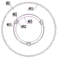
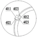
The working principle of the clamping and rotating device 4 is shown in fig. 8 and 9, the clamping and rotating device 4 comprises an outer ring 401, a transmission arm 402 and an inner ring 403, a gear ring 4011 is arranged outside the outer ring 401, the gear ring 4011 is in matched transmission with the driving gear 303, and a plurality of transmission gaps 4012 are arranged inside the outer ring 401; the inner ring 403 and the outer ring 401 are concentrically arranged, and a clamping notch 4031 is arranged at the position, close to the transmission notch 4012, of the inner ring 403; the driving arm 402 is rotatably installed on the clamping notch 4031, the driving arm 402 is composed of a driving end 4021, a mounting hole 4022 and a clamping end 4023, the driving end 4021 is arranged inside the driving notch 4012, and the clamping end 4023 can outwards extend around the inner pin shaft of the mounting hole 4022 under the poking of the driving end 4021 to clamp the fixed inner electrode 8.
During specific work, motor 301 installed on one side of base 1 is electric retarder 302 in proper order, drive gear 303 is rotatory, drive gear 303 meshes with gear circle 4011, outer lane 401 rotates under the effect of external force, along with the rotation of outer lane 401, the inside transmission breach 4012 of outer lane 401 also begins to rotate, when the inner wall of transmission breach 4012 contacts the transmission end 4021 of transmission arm 402, transmission arm 402 is stirred, when transmission arm 402 rotates to extreme position around the inside round pin axle of mounting hole 4022, the side of transmission arm 402 is blocked by the inner wall of step-up breach 4031, outer lane 401 and inner circle 403 link together through transmission arm 402, clockwise, during the motion, the step-up end 4023 of transmission arm 402 outwards stretches out in order to step up fixed inside electrode 7, new through the rotation has been realized, the butt joint of old electrode, the extension work of electrode has also been accomplished.
The utility model provides a novel device can utilize the leading truck of top to install extension electrode fast, can be high-efficient, reliable clamp tightly and drive new electrode rotation in order to realize the threaded connection between new, the old electrode based on novel tight rotary device that presss from both sides, simultaneously, this scheme has still designed bottom fixing device and has been used for pressing from both sides tight old electrode, has further increased the practicality of equipment, and the device's popularization can reduce off-line smelting auxiliary assembly in electrode extension's intensity of labour and potential safety hazard.
Finally, it should be noted that: the above embodiments are only used to illustrate the technical solution of the present invention, and not to limit it; although the present invention has been described in detail with reference to the foregoing embodiments, it should be understood by those skilled in the art that: the technical solutions described in the foregoing embodiments may still be modified, or some technical features may be equivalently replaced; such modifications and substitutions do not depart from the spirit and scope of the present invention in its corresponding aspects.
Claims (7)
1. The utility model provides an automatic extension device of electrode off-line, its characterized in that includes base (1), guide frame (2), drive arrangement (3), presss from both sides tight rotary device (4), compensation arrangement (5) and fixing device (6), wherein:
the base (1) is used as a load-bearing main body and comprises a supporting plate (101), a guiding cavity (102) and a connecting flange (103), the supporting plate (101) is installed at the top of the guiding cavity (102), and the connecting flange (103) is installed at the bottom of the guiding cavity (102) and used for being connected with a submerged arc furnace device;
the guide frame (2) is arranged at the top of the support plate (101) and used for guiding a new electrode (7) to enter the base (1), the guide frame (2) comprises a first support (201) and a second support (202) which are oppositely arranged, an upper guide wheel and a lower guide wheel (203) are arranged at the top of the first support (201), a rotary guide wheel (204) is arranged at the top of the second support (202), and a space for the new electrode (7) to pass through is formed between the upper guide wheel and the lower guide wheel (203) and the rotary guide wheel (204);
the driving device (3) is arranged on one side of the base (1) and drives the clamping and rotating device (4) to work through a gear;
the tight rotating device (4) is used for clamping and driving the new electrode (7) to rotate so as to realize threaded connection between the new electrode (7) and the old electrode (8), the tight rotating device (4) is installed at the top of the compensating device (5) through a bearing, and the compensating device (5) is installed inside the supporting plate (101);
fixing device (6) are used for pressing from both sides tight old electrode (8) and include actuating cylinder (601), hydro-cylinder seat (602), press from both sides tight rocking arm (603) and rocker arm base (604), the bottom of actuating cylinder (601) articulates on hydro-cylinder seat (602), press from both sides tight rocking arm (603) and articulate on rocker arm base (604), press from both sides the telescopic link of connecting actuating cylinder (601) of the one end of tight rocking arm (603), press from both sides tight rocking arm (603) and realize the swing motion under the drive of actuating cylinder (601), the other end that presss from both sides tight rocking arm (603) can stretch into guide chamber (102) inside and fix old electrode (8).
2. The off-line automatic electrode lengthening device according to claim 1, wherein the upper and lower guide wheels (203) comprise a first tapered wheel (2031) and a second tapered wheel (2032) which are symmetrically arranged, and the rotary guide wheel (204) comprises a first round wheel (2041) and a second round wheel (2042) which are symmetrically arranged, wherein:
the rotation centers of the first conical wheel (2031) and the second conical wheel (2032) are vertical to the center of the new electrode (7), and the side surfaces of the first conical wheel (2031) and the second conical wheel (2032) are used for leading the new electrode (7) to move up and down; the rotation centers of the first round wheel (2041) and the second round wheel (2042) are parallel to the center of the new electrode (7), and the side surfaces of the first round wheel (2041) and the second round wheel (2042) are used for guiding the screwing action of the old electrode (8).
3. The electrode offline automatic lengthening device according to claim 2, wherein the bottom of each of the first bracket (201) and the second bracket (202) is provided with a pulley adjusting device (205), the pulley adjusting device (205) comprises a fixing screw (2051), a slider (2052), a chute (2053), a first adjusting bolt (2054) and a second adjusting bolt (2055), wherein:
the bottom of first support (201) and second support (202) is installed on slider (2052) through fixed screw (2051), with spout (2053) that slider (2052) corresponds set up on backup pad (101), and first adjusting bolt (2054) and second adjusting bolt (2055) set up respectively in the both sides of slider (2052), can drive slider (2052) and remove in order to realize the distance between first support (201) and second support (202) in spout (2053) through the extension length of adjusting first adjusting bolt (2054) and second adjusting bolt (2055).
4. The electrode offline automatic lengthening device according to claim 3, wherein the fixing device (6) further comprises a rocker slider (605) and a base adjusting device (606), the rocker base (604) is mounted on the rocker slider (605), the base adjusting device (606) is arranged on two sides of the rocker slider (605), and the position of the rocker base (604) can be adjusted through the base adjusting device (606) to change the action range of the clamping rocker (603).
5. The electrode offline automatic lengthening device according to claim 4, wherein said compensation device (5) comprises a bottom plate (501), a lifting plate (502), a guide cavity (503), a spring (504), a support rod (505) and a cushion washer (506), wherein: the bottom plate (501) is installed on the supporting plate (101), the bottom of installing at lifter plate (502) of direction chamber (503), the opening of direction chamber (503) is down, the bottom of bracing piece (505) is fixed on bottom plate (501), the top of bracing piece (505) is installed inside direction chamber (503), spring (504) are installed in the space that direction chamber (503) inner wall and bracing piece (505) top formed, cushion ring (506) cover is established in the bottom of bracing piece (505).
6. The electrode offline automatic lengthening device according to claim 5, wherein the driving device (3) comprises a motor (301), a reducer (302) installed at the output end of the motor (301), and a driving gear (303) installed at the output end of the reducer (302), and a torque sensor (304) is further arranged on the output shaft of the reducer (302).
7. The electrode offline automatic lengthening device according to claim 6, wherein said clamping rotation device (4) comprises an outer ring (401), a transmission arm (402) and an inner ring (403), wherein: a gear ring (4011) is arranged outside the outer ring (401), the gear ring (4011) is in matched transmission with the driving gear (303), and a plurality of transmission notches (4012) are formed inside the outer ring (401); the inner ring (403) and the outer ring (401) are concentrically arranged, and a clamping notch (4031) is arranged at the position, close to the transmission notch (4012), of the inner ring (403); the rotatable installation of transmission arm (402) is on step up breach (4031), transmission arm (402) comprises transmission end (4021), mounting hole (4022) and step up end (4023), transmission end (4021) sets up inside transmission breach (4012), step up end (4023) can be under the stirring of transmission end (4021) outwards stretch out around mounting hole (4022) internal pin axle in order to step up fixed inside electrode (7).
Priority Applications (1)
| Application Number | Priority Date | Filing Date | Title |
|---|---|---|---|
| CN201921981701.2U CN211079211U (en) | 2019-11-18 | 2019-11-18 | Electrode off-line type automatic lengthening device |
Applications Claiming Priority (1)
| Application Number | Priority Date | Filing Date | Title |
|---|---|---|---|
| CN201921981701.2U CN211079211U (en) | 2019-11-18 | 2019-11-18 | Electrode off-line type automatic lengthening device |
Publications (1)
| Publication Number | Publication Date |
|---|---|
| CN211079211U true CN211079211U (en) | 2020-07-24 |
Family
ID=71638154
Family Applications (1)
| Application Number | Title | Priority Date | Filing Date |
|---|---|---|---|
| CN201921981701.2U Active CN211079211U (en) | 2019-11-18 | 2019-11-18 | Electrode off-line type automatic lengthening device |
Country Status (1)
| Country | Link |
|---|---|
| CN (1) | CN211079211U (en) |
Cited By (2)
| Publication number | Priority date | Publication date | Assignee | Title |
|---|---|---|---|---|
| CN114672613A (en) * | 2022-03-24 | 2022-06-28 | 广东韶钢松山股份有限公司 | Electrode connecting device |
| CN117650406A (en) * | 2024-01-29 | 2024-03-05 | 苏州朗信智能科技有限公司 | Electrode lengthening robot |
-
2019
- 2019-11-18 CN CN201921981701.2U patent/CN211079211U/en active Active
Cited By (2)
| Publication number | Priority date | Publication date | Assignee | Title |
|---|---|---|---|---|
| CN114672613A (en) * | 2022-03-24 | 2022-06-28 | 广东韶钢松山股份有限公司 | Electrode connecting device |
| CN117650406A (en) * | 2024-01-29 | 2024-03-05 | 苏州朗信智能科技有限公司 | Electrode lengthening robot |
Similar Documents
| Publication | Publication Date | Title |
|---|---|---|
| CN211079211U (en) | Electrode off-line type automatic lengthening device | |
| CN202701652U (en) | Welding manipulator with clamping mechanism | |
| CA2719334C (en) | Device for adjusting the locking point of an electrode | |
| CN219945210U (en) | Automatic electrode lengthening device | |
| CN112008350A (en) | Automatic electrode lengthening device | |
| CN102430684A (en) | Multifunctional hydraulic track forging manipulator | |
| CN102625508B (en) | Electrode lifting mechanism with adjustable electrode circle, furnace cover and electric arc furnace | |
| CN211084846U (en) | Automatic clamping device for electrode extension | |
| CN201132845Y (en) | Device for overturning electrode | |
| CN213738437U (en) | Lifting appliance lifter with rotary supporting arm | |
| CN211012461U (en) | Electric arc furnace and furnace cover thereof | |
| CN209639495U (en) | Continuous charging electric furnace arrangement for producing steel device | |
| CN210023753U (en) | Material receiving device for intermediate frequency furnace | |
| CN215638799U (en) | Electric arc furnace bell lifting arm | |
| CN214371657U (en) | Cantilever position detection device for electric arc furnace | |
| CN218320522U (en) | Steel rope tensioning and guiding mechanism of hoisting equipment for producing refractory stemming | |
| CN219829499U (en) | Telescopic cylinder for vacuum consumable stove | |
| CN220931681U (en) | Hydraulic motor driven mechanical rotary feeding device | |
| CN111994783B (en) | Automatic electrode lifting appliance | |
| CN202630699U (en) | Electrode-circle-adjustable novel electrode lifting mechanism and electric arc furnace | |
| CN110790119A (en) | Special lifting appliance for large electric furnace body | |
| CN215799695U (en) | Feeding device for ladle refining furnace | |
| CN210528965U (en) | Furnace wall telescopic carbon-oxygen gun manipulator | |
| CN219944612U (en) | Ladle tipping device of rotary table | |
| CN216192458U (en) | Molten iron desulfurizer adding device |
Legal Events
| Date | Code | Title | Description |
|---|---|---|---|
| GR01 | Patent grant | ||
| GR01 | Patent grant | ||
| TR01 | Transfer of patent right | ||
| TR01 | Transfer of patent right |
Effective date of registration: 20200811 Address after: 710075 2-2004, no.6, Gaoxin Road, Zhangba Street office, high tech Zone, Xi'an City, Shaanxi Province Patentee after: Xiye Technology Group Co., Ltd Address before: 710077 811, floor 8, Xinyuan center, Fenghe Road, Lianhu District, Xi'an City, Shaanxi Province Patentee before: Dongfang Huachuang Engineering Technology Co.,Ltd. |