CN211053296U - Automatic polishing equipment - Google Patents
Automatic polishing equipment Download PDFInfo
- Publication number
- CN211053296U CN211053296U CN201921542324.2U CN201921542324U CN211053296U CN 211053296 U CN211053296 U CN 211053296U CN 201921542324 U CN201921542324 U CN 201921542324U CN 211053296 U CN211053296 U CN 211053296U
- Authority
- CN
- China
- Prior art keywords
- along
- inner cavity
- sides
- slide
- workbench
- Prior art date
- Legal status (The legal status is an assumption and is not a legal conclusion. Google has not performed a legal analysis and makes no representation as to the accuracy of the status listed.)
- Expired - Fee Related
Links
Images


Abstract
The utility model discloses an automatic change equipment of polishing, including base and polisher, the top rear side central point of base puts and installs the polisher along upper and lower direction, the inner chamber front side central point of base puts along upper and lower direction screw connection has the motor, and the output of motor extends the top surface and the key-type connection of base has the gear, the front side that both sides are located the polisher around the top has the slide, two along the equal screw connection of left and right sides direction slide's the outside is located the top of base and has all seted up the slide rail, the inner chamber of slide is pegged graft and is had the slider, and both sides are connected with the pulley through the round pin hub connection along the left and right sides around the inner chamber of slider, the bottom of slider is extended to the bottom of pulley and. This automatic change equipment of polishing need not repeated material loading polish, can carry out stable centre gripping to the piece of polishing of thickness difference, has guaranteed workpiece surface's processing demand, has reduced the labour, has improved work efficiency, has improved processingquality.
Description
Technical Field
The utility model relates to the technical field of machining, specifically be an automatic change equipment of polishing.
Background
Polishing, one of surface modification technologies, generally refers to a processing method for changing physical properties of a material surface by friction with the help of a rough object (sand paper containing particles with higher hardness, etc.), and the main purpose is to remove burrs on the surface of a workpiece of a product, make the workpiece smooth, and easily continue to process or reach a finished product.
SUMMERY OF THE UTILITY MODEL
An object of the utility model is to provide an automatic change equipment of polishing to solve the problem that proposes among the above-mentioned background art.
In order to achieve the above object, the utility model provides a following technical scheme: an automatic polishing device comprises a base and a polishing machine, wherein the polishing machine is installed at the center position of the rear side of the top end of the base along the up-down direction, a motor is connected at the center position of the front side of an inner cavity of the base along the up-down direction through screws, the output end of the motor extends out of the surface of the top end of the base and is connected with a gear through keys, slide ways are connected at the front sides of the front side and the rear side of the top end of the base along the left-right direction through screws, slide rails are arranged at the top ends of the two slide ways on the outer side of the base, a slide block is inserted into the inner cavity of each slide way, pulleys are connected at the front sides and the rear sides of the inner cavity of each slide block along the left-right direction through pin shafts, the bottom end of each pulley extends out of the bottom end of each, the gear is meshed and connected with a rack on the front side of the baffle, a chute is arranged on the top end of an inner cavity of the workbench along the left-right direction, the upper side and the lower side of the inner cavity of the chute are respectively communicated with the top end of the workbench and the bottom end of the inner cavity of the workbench, pillars are inserted into the left side and the right side of the inner cavity of the chute along the up-down direction, the upper end and the lower end of each pillar respectively extend out of the outer wall on the top end of the workbench and the bottom end of the inner cavity of the workbench, the left side and the right side of the bottom end of the inner cavity of the workbench are respectively connected with a first screw rod through a bearing, the left end and the right end of the outer wall of the first screw rod extend out of the outer wall surface on the right side of the workbench and are connected with a first hand wheel in a key mode, the inner cavity of the groove is connected with a first connecting block through a bearing, the surface of the outer wall of the first connecting block is in interference fit with an inner ring of the bearing, the surface of the inner wall of the groove is fixedly connected with an outer ring of the bearing, the top ends of the outer sides of the two struts are inserted with second screw rods along the left-right direction, the second screw rods extend into the inner cavity of the groove and are in threaded connection with the first connecting block, the inner ends of the outer walls of the two second screw rods extend out of the inner sides of the two first connecting blocks and are connected with second connecting blocks through the bearing, the inner sides of the outer walls of the two second screw rods are in interference fit with the inner ring of the bearing, the surface of the outer sides of the two second connecting blocks is fixedly connected with the outer ring of the bearing, the front sides and the rear sides of the upper end and the lower end of the inner sides of the two first connecting blocks are symmetrically connected with clamping jaws along the, four the other end of ejector pin all puts through the round pin hub connection rather than the central point that corresponds the position clamping jaw, the draw-in groove has been seted up along circumference to the outer wall that the inboard of recess is located first connecting block, two the top of pillar has the bayonet lock along upper and lower direction spiro union, and the bottom of bayonet lock extend into the inner chamber of recess and with the draw-in groove joint, two the outer wall outer end of first screw rod all extends the outside surface and the key-type connection of two pillars and has the second hand wheel.
Preferably, at least five pulleys are installed in the inner cavity of the sliding block, and the pulleys are arranged at intervals in the left-right direction.
Preferably, the inner cavity of the slide way is in a dovetail groove shape, and the slide block is in adaptive insertion connection with the slide way.
Preferably, the two second screws are located on the same horizontal plane and on the same straight line.
Preferably, the four clamping jaws are equal in length, and inclined planes are arranged on the outer walls of the clamping jaws.
Compared with the prior art, the beneficial effects of the utility model are that: this automatic change equipment of polishing drives the baffle through motor drive gear, makes the workstation remove about and can polish repeatedly to the piece of polishing, does not need the repetition material loading to polish, and it is rotatory through second hand-wheel drive second screw rod, makes first connecting block drive ejector pin horizontal hunting drive clamping jaw expansion or shrink, can carry out stable centre gripping to the piece of polishing of thickness difference, has guaranteed workpiece surface's processing demand, has reduced the labour, has improved work efficiency, has improved processingquality.
Drawings
Fig. 1 is a front view of the present invention;
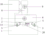
FIG. 2 is a front sectional view of the present invention;
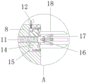
FIG. 3 is an enlarged view of the point A of the present invention;
fig. 4 is a left side view of the present invention.
In the figure: 1. the grinding machine comprises a base, 2, a slide rail, 3, a slide rail, 4, a slide block, 5, a gear, 6, a workbench, 7, a first hand wheel, 8, a support column, 9, a second hand wheel, 10, a grinding machine, 11, a second screw rod, 12, a clamping pin, 13, a pulley, 14, a first connecting block, 15, a groove, 16, a second connecting block, 17, an ejector rod, 18, a clamping jaw, 19, a motor, 20, a baffle plate, 21, a sliding groove, 22 and a first screw rod.
Detailed Description
The technical solutions in the embodiments of the present invention will be described clearly and completely with reference to the accompanying drawings in the embodiments of the present invention, and it is obvious that the described embodiments are only some embodiments of the present invention, not all embodiments. Based on the embodiments in the present invention, all other embodiments obtained by a person skilled in the art without creative work belong to the protection scope of the present invention.
Referring to fig. 1-4, the present invention provides a technical solution: an automatic polishing device comprises a base 1 and a polishing machine 10, wherein the polishing machine 10 is installed at the center position of the rear side of the top end of the base 1 along the up-down direction, a motor 19 is connected to the center position of the front side of an inner cavity of the base 1 along the up-down direction through screws, power is provided for a gear 5 driving workbench 6 through the motor 19, the output end of the motor 19 extends out of the top end surface of the base 1 and is connected with the gear 5 in a key mode, slide rails 2 are connected to the front side of the polishing machine 10 along the left-right direction through screws on the front side and the rear side of the top end of the base 1, slide rails 3 are arranged on the outer sides of the two slide rails 2 and are arranged at the top end of the base 1, a pulley 13 can stably move along the slide rails 3 through the slide rails 3, a slide block 4 is inserted into the inner cavity of the slide rails 2, the top end of the sliding block 4 is welded with a workbench 6, the bottom end of the workbench 6 is welded with a baffle 20 along the left-right direction, the front side of the baffle 20 is provided with racks along the left-right direction, the gear 5 is meshed with the racks on the front side of the baffle 20, the top end of the inner cavity of the workbench 6 is provided with a chute 21 along the left-right direction, the upper side and the lower side of the inner cavity of the chute 21 are respectively communicated with the top end of the workbench 6 and the bottom end of the inner cavity of the workbench 6, the left side and the right side of the inner cavity of the chute 21 are inserted with a strut 8 along the up-down direction, the upper end and the lower end of the strut 8 respectively extend out of the outer wall of the top end of the workbench 6 and the bottom end of the inner cavity of the workbench 6, the left side and the right side of the inner cavity of the workbench 6 are respectively connected with a first screw 22 through a bearing, the two ends of a polishing, the right end of the outer wall of the first screw 22 extends out of the right outer wall surface of the workbench 6 and is connected with a first hand wheel 7 in a key mode, the top end surfaces of the inner sides of the two struts 8 are respectively provided with a groove 15, the inner cavity of each groove 15 is connected with a first connecting block 14 through a bearing, the clamping jaws are fixed and rotated through the first connecting blocks 14, the outer wall surfaces of the first connecting blocks 14 are in interference fit with inner rings of the bearings, the inner wall surfaces of the grooves 15 are fixedly connected with outer rings of the bearings, the top ends of the outer sides of the two struts 8 are respectively inserted with second screws 11 along the left and right direction, the second connecting blocks 16 are pushed and pulled left and right through the second screws 11, the second screws 11 extend into the inner cavities of the grooves 15 and are in threaded connection with the first connecting blocks 14, the inner ends of the outer walls of the two second screws 11 extend out of the inner sides of the two first connecting blocks 14 and, inner sides of outer walls of the two second screw rods 11 are both in interference fit with an inner ring of a bearing, outer surfaces of outer sides of the two second connecting blocks 16 are both fixedly connected with an outer ring of the bearing, front and back sides of upper and lower ends of inner sides of the two first connecting blocks 14 are both symmetrically connected with clamping jaws 18 through pin shafts along the left and right direction, front and back sides of upper and lower ends of inner sides of the two second connecting blocks 16 are both symmetrically connected with one ends of ejector rods 17 through pin shafts along the left and right direction, the ejector rods 17 push and pull the clamping jaws 18 up and down, so that the grinding parts are clamped by the clamping jaws 18, the other ends of the four ejector rods 17 are connected with the central positions of the clamping jaws 18 corresponding to the other ends through pin shafts, the inner sides of the grooves 15 are positioned on the outer walls of the first connecting blocks 14 and are circumferentially provided with clamping grooves, clamping pins 12 are screwed on the top, and the bottom of bayonet lock 12 extends into the inner chamber of recess 15 and with the draw-in groove joint, the outer end of the outer wall of two first screw rods 11 all extends the outside surface of two pillars 8 and the key-type is connected with second hand wheel 9.
The following electric devices have the following types and functions:
the sander 10: is a double-sided grinding and polishing machine with the model of OB-80A and is used for grinding a grinding piece.
The motor 19: is a speed reducing motor with the model number of R107R77 and is used for driving the gear 5 to drive the workbench 6 to move left and right.
Preferably, at least five pulleys 13 are installed in the inner cavity of the sliding block 4, the pulleys 13 are arranged at intervals in the left-right direction, and the working table is supported by the pulleys 13, so that the stability of the working table in the moving process is ensured.
Preferably, the inner cavity of the slide way 2 is in a dovetail groove shape, the slide block 4 is inserted into the slide way 2 in a matching manner, and the slide block 4 can move stably along the inner cavity of the slide way 2 through the slide way 2.
As a preferred scheme, furthermore, the two second screws 7 are located on the same horizontal plane and on the same straight line, so that accurate clamping of the workpiece is guaranteed, and influence on processing quality is avoided.
Preferably, the four clamping jaws 18 are equal in length, and the outer walls of the clamping jaws 18 are provided with inclined surfaces, so that when the grinding part is sleeved on the clamping jaws 18 to be fixed, the contact area between the grinding part and the workpiece is increased through the inclined surfaces, and the clamping jaws 18 can be fixed to the workpiece more firmly.
All the electrical components in the present application are connected with the power supply adapted to the electrical components through the wires, and an appropriate controller should be selected according to actual conditions to meet the control requirements, and specific connection and control sequences should be obtained.
The detailed connection means is a technique known in the art, and the following mainly describes the working principle and process, and the specific operation is as follows.
When the grinding machine is used, the distance between two grinding wheels on the grinding machine 10 is adjusted according to the height of a grinding piece, the two ends of the grinding piece are inserted between the clamping jaws 18 or sleeved on the outer walls of the clamping jaws 18 according to the opening sizes of the two ends of the grinding piece, the first hand wheel 7 is rotated clockwise, the first hand wheel 7 drives the first screw 22 to drive the two upright rods 8 to move towards the center of the first screw 22, so that the grinding piece is clamped, the two second hand wheels 9 are rotated clockwise or anticlockwise respectively, the second hand wheel 9 drives the second screw 11 to push or pull the second connecting block 16 to move, the second connecting block 16 drives one end of the ejector rod 17 to swing, meanwhile, the second connecting block 16 pushes or pulls the other end of the ejector rod 17 upwards, so that the four clamping jaws 18 simultaneously contract inwards or expand outwards, so that the grinding piece is fixed and clamped, and the external power supply of the grinding machine 10 and the motor 19, the gear 5 is driven by the motor 19 to rotate clockwise, the gear 5 drives the rack to drive the workbench 6 to move rightwards, so that the upper end and the lower end of a polishing piece are simultaneously polished by the polisher 10, the pulley 13 supports the workbench 6 to roll rightwards along the slide rail 3, the rightwards movement distance of the workbench 6 reaches the maximum when the left end teeth of the rack are meshed with the gear 5, the motor 19 starts to rotate anticlockwise, the rack is driven to drive the workbench 6 to move leftwards, the leftward movement distance of the workbench 6 reaches the maximum when the right end teeth of the rack are meshed with the gear 5, the motor 19 continues to rotate clockwise, the workbench 6 is driven to move rightwards, the polishing piece is repeatedly polished, after the upper end and the lower end of the polishing piece are polished, the polisher 10 is stopped, the bayonet lock 12 is unscrewed, the bayonet lock 12 is separated from the first connecting block 16, the second wheel 9 is rotated, the polishing piece, make the locking of first connecting block 16, adjust the interval of the wheel of polishing on polisher 10 according to the processing demand, this equipment makes workstation 6 reciprocating motion about through the external power supply of switch-on motor 19 to carry out comprehensive polishing to the piece of polishing, to polishing a fixed stability, prevent to rock, improved the quality of machining precision and product, increased the practicality, more be favorable to promoting.
In the description of the present invention, it is to be understood that the terms "coaxial", "bottom", "one end", "middle", "other end", "upper", "one side", "top", "inner", "front", "center", "both ends", and the like, indicate orientations or positional relationships based on the orientations or positional relationships shown in the drawings, and are only for convenience of description and simplicity of description, and do not indicate or imply that the device or element being referred to must have a particular orientation, be constructed and operated in a particular orientation; also, unless expressly stated or limited otherwise, the terms "screw connection," "keyed connection," "plug-in connection," "welded connection," "pin connection," "engaged connection," "bearing connection," "interference fit," "fixed connection," "threaded connection," and the like are to be construed broadly and may be, for example, a fixed connection, a removable connection, or an integral part; can be mechanically or electrically connected; they may be directly connected or indirectly connected through an intermediate medium, and may be connected through the inside of two elements or in an interaction relationship between two elements, unless otherwise specifically defined, and the specific meaning of the above terms in the present invention will be understood by those skilled in the art according to specific situations.
Although embodiments of the present invention have been shown and described, it will be appreciated by those skilled in the art that changes, modifications, substitutions and alterations can be made in these embodiments without departing from the principles and spirit of the invention, the scope of which is defined in the appended claims and their equivalents.
Claims (5)
1. The utility model provides an automatic change equipment of polishing, includes base (1) and polisher (10), its characterized in that are installed along the upper and lower direction to the top rear side central point of base (1): the grinding machine is characterized in that a motor (19) is connected to the center of the front side of an inner cavity of the base (1) along the up-down direction through screws, the output end of the motor (19) extends out of the top surface of the base (1) and is in key connection with a gear (5), the front sides of the front side and the rear side of the top end of the base (1) are in screw connection with slide ways (2) along the left-right direction, slide rails (3) are arranged on the top ends of the base (1) at the outer sides of the two slide ways (2), a slide block (4) is inserted into the inner cavity of the slide way (2), pulleys (13) are connected to the front sides and the rear sides of the inner cavity of the slide block (4) along the left-right direction through pin shafts, the bottom end of each pulley (13) extends out of the bottom end of the slide block (4) and is inserted into the slide rails (3), the front side of the baffle plate (20) is provided with a rack along the left-right direction, the gear (5) is meshed and connected with the rack on the front side of the baffle plate (20), the top end of the inner cavity of the workbench (6) is provided with a chute (21) along the left-right direction, the upper side and the lower side of the inner cavity of the chute (21) are respectively communicated with the top end of the workbench (6) and the bottom end of the inner cavity of the workbench (6), the left side and the right side of the inner cavity of the chute (21) are respectively inserted with a strut (8) along the up-down direction, the upper end and the lower end of the strut (8) respectively extend out of the outer wall of the top end of the workbench (6) and the bottom end of the inner cavity of the workbench (6), the left side and the right side of the inner cavity bottom end of the workbench (6) are respectively connected with a first screw rod (22) through a bearing, the left end and the right, the right end of the outer wall of the first screw rod (22) extends out of the surface of the outer wall on the right side of the workbench (6) and is connected with a first hand wheel (7) in a key-joint mode, grooves (15) are formed in the top end surfaces of the inner sides of the two supporting columns (8), the inner cavities of the grooves (15) are connected with first connecting blocks (14) through bearings, the inner ring of the bearing is in interference fit with the surface of the outer wall of each first connecting block (14), the outer ring of the bearing is fixedly connected with the surface of the inner wall of each groove (15), second screw rods (11) are inserted into the top ends of the outer sides of the two supporting columns (8) in the left-right direction, the inner cavities of the second screw rods (11) extending into the grooves (15) are in threaded connection with the first connecting blocks (14), the inner ends of the outer walls of the two second screw rods (11) extend out of the inner sides of the two first connecting blocks (14) and are connected with second connecting blocks, the outer side surfaces of the two second connecting blocks (16) are fixedly connected with outer rings of bearings, the front and rear sides of the upper and lower ends of the inner sides of the two first connecting blocks (14) are symmetrically connected with clamping jaws (18) through pin shafts along the left and right direction, the front and rear sides of the upper and lower ends of the inner sides of the two second connecting blocks (16) are symmetrically connected with one end of a push rod (17) through pin shafts along the left and right direction, the other ends of the four push rods (17) are connected with the central position of the clamping jaws (18) at the corresponding positions through pin shafts, the inner side of the groove (15) is positioned on the outer wall of the first connecting block (14) and is provided with a clamping groove along the circumferential direction, the top ends of the two struts (8) are screwed with clamping pins (12) along the up-down direction, and the bottom of bayonet lock (12) extends into the inner chamber of recess (15) and with the bayonet lock joint, two the outer wall outer end of second screw rod (11) all extends the outside surface parallel key-type connection of two pillars (8) and has second hand wheel (9).
2. An automated milling apparatus according to claim 1, wherein: at least five pulleys (13) are installed in the inner cavity of the sliding block (4), and the pulleys (13) are arranged in a left-right direction at intervals.
3. An automated milling apparatus according to claim 1, wherein: the inner cavity of the slide way (2) is in a dovetail groove shape, and the sliding block (4) is in adaptive insertion connection with the slide way (2).
4. An automated milling apparatus according to claim 1, wherein: the two second screws (11) are positioned on the same horizontal plane and on the same straight line.
5. An automated milling apparatus according to claim 1, wherein: the four clamping jaws (18) are equal in length, and inclined planes are arranged on the outer walls of the clamping jaws (18).
Priority Applications (1)
| Application Number | Priority Date | Filing Date | Title |
|---|---|---|---|
| CN201921542324.2U CN211053296U (en) | 2019-09-17 | 2019-09-17 | Automatic polishing equipment |
Applications Claiming Priority (1)
| Application Number | Priority Date | Filing Date | Title |
|---|---|---|---|
| CN201921542324.2U CN211053296U (en) | 2019-09-17 | 2019-09-17 | Automatic polishing equipment |
Publications (1)
| Publication Number | Publication Date |
|---|---|
| CN211053296U true CN211053296U (en) | 2020-07-21 |
Family
ID=71594365
Family Applications (1)
| Application Number | Title | Priority Date | Filing Date |
|---|---|---|---|
| CN201921542324.2U Expired - Fee Related CN211053296U (en) | 2019-09-17 | 2019-09-17 | Automatic polishing equipment |
Country Status (1)
| Country | Link |
|---|---|
| CN (1) | CN211053296U (en) |
Cited By (1)
| Publication number | Priority date | Publication date | Assignee | Title |
|---|---|---|---|---|
| CN112345140A (en) * | 2020-10-22 | 2021-02-09 | 东莞理工学院 | Production equipment with stripping torque detection function for synchronous gear ring machining |
-
2019
- 2019-09-17 CN CN201921542324.2U patent/CN211053296U/en not_active Expired - Fee Related
Cited By (1)
| Publication number | Priority date | Publication date | Assignee | Title |
|---|---|---|---|---|
| CN112345140A (en) * | 2020-10-22 | 2021-02-09 | 东莞理工学院 | Production equipment with stripping torque detection function for synchronous gear ring machining |
Similar Documents
| Publication | Publication Date | Title |
|---|---|---|
| CN210209983U (en) | Numerical control machining machine tool for tungsten steel grinding head | |
| CN211414808U (en) | Integrative frock of usefulness is polished in welding | |
| CN209110183U (en) | A kind of double main shaft Automatic Lathes | |
| CN110524344B (en) | Automatic equipment and processing method for grinding plane and chamfer of silicon rod | |
| CN212794297U (en) | Polishing equipment based on stainless steel product edge | |
| CN211053296U (en) | Automatic polishing equipment | |
| CN113664719A (en) | Aluminum alloy die casting finishing machine and method thereof | |
| CN210548133U (en) | Vertical turning device for processing inner and outer spoke bottoms of automobile spokes | |
| CN209998927U (en) | Full-automatic internal polishing machine | |
| CN111745225A (en) | Engraving and milling device for machining and using method thereof | |
| CN111438570A (en) | Precision processing method for sintered and molded metal powder metallurgy product | |
| CN218081951U (en) | High-efficient automatic rotatory hydraulic pressure foundry goods processing frock | |
| CN215919308U (en) | Workpiece deburring device | |
| CN210499413U (en) | Workpiece transfer device for part machining | |
| CN211135675U (en) | Automatic end face milling machine for aluminum profile | |
| CN210209720U (en) | Hole repairing device for workpiece for machining | |
| CN215432832U (en) | Blade blank processingequipment with locate function | |
| CN112264889A (en) | Automobile part polishing device and polishing method thereof | |
| CN219945503U (en) | Tool for cylindrical grinding of long shaft part | |
| CN112025524A (en) | Burnishing device of hardware product processing usefulness convenient to location | |
| CN219094593U (en) | Clamp jig with pouring gate polishing function | |
| CN220561172U (en) | High-precision numerical control roller grinding machine | |
| CN216298865U (en) | Adjustable polishing device for machining mechanical parts | |
| CN220073472U (en) | Grinding machine for gear machining | |
| CN219805832U (en) | Adjustable deburring mechanism |
Legal Events
| Date | Code | Title | Description |
|---|---|---|---|
| GR01 | Patent grant | ||
| GR01 | Patent grant | ||
| CF01 | Termination of patent right due to non-payment of annual fee | ||
| CF01 | Termination of patent right due to non-payment of annual fee |
Granted publication date: 20200721 Termination date: 20210917 |