CN211020038U - Trimming means that garden lawn used - Google Patents
Trimming means that garden lawn used Download PDFInfo
- Publication number
- CN211020038U CN211020038U CN201921885532.2U CN201921885532U CN211020038U CN 211020038 U CN211020038 U CN 211020038U CN 201921885532 U CN201921885532 U CN 201921885532U CN 211020038 U CN211020038 U CN 211020038U
- Authority
- CN
- China
- Prior art keywords
- grass
- install
- adjusting screw
- organism
- machine body
- Prior art date
- Legal status (The legal status is an assumption and is not a legal conclusion. Google has not performed a legal analysis and makes no representation as to the accuracy of the status listed.)
- Active
Links
Images


Abstract
The utility model discloses a trimming means that garden lawn used, which comprises a bod, one side of organism is installed and is pushed away the handle, install two guide bars of symmetry in the organism, two equal sliding connection has the uide bushing on the guide bar, two install the mounting panel on the uide bushing jointly, install the motor on the mounting panel, install the grass cutting wheel on the output shaft of motor, two common fixedly connected with connecting rod in the uide bushing, the connector is installed to the connecting rod upper end, install adjusting screw on the connector. The utility model discloses an adjusting screw's rotation drives the change of mowing wheel height for planting grass to co-altitude not that can be better is pruned, and the thickness of better control pruning dredges the design of grass board and notch simultaneously, can comb planting grass, blocks objects such as great stone simultaneously, avoids bumping with mowing wheel, causes pedestrian's injury.
Description
Technical Field
The utility model relates to a garden instrument technical field especially relates to a trimming means that garden lawn used.
Background
In order to improve the trimming efficiency of the lawn, a lawn mower is generally adopted to trim the lawn, so that the labor intensity of manual trimming is reduced, and a common lawn mower generally pushes a machine body or drives the machine body manually, so as to trim the lawn along with the movement of the machine body;
traditional lawn mower blade is not convenient for adjust, is not convenient for prune according to the vegetation thickness on lawn, and the blade of just mowing when rotating, if meet objects such as stone, fly out easily under the centrifugal force effect, cause the influence easily to personal safety.
SUMMERY OF THE UTILITY MODEL
The utility model aims at solving the problems existing in the prior art and providing a pruning device for a garden lawn.
In order to achieve the above purpose, the utility model adopts the following technical scheme:
the utility model provides a trimming means that garden lawn used, includes the organism, one side of organism is installed and is pushed away the handle, install two guide bars of symmetry in the organism, two equal sliding connection has the uide bushing on the guide bar, two install the mounting panel on the uide bushing jointly, install the motor on the mounting panel, install grass cutting wheel on the output shaft of motor, two common fixedly connected with connecting rod is gone up to the uide bushing, the connector is installed to the connecting rod upper end, install adjusting screw on the connector, the organism is kept away from the one end that pushes away the handle and is installed grass thinning mechanism.
Preferably, grass thinning mechanism is including thinning out grass board, notch, connecting cylinder, backup pad, buffer spring, connecting rod and location screw thread, keep away from the one end fixedly connected with backup pad of push pedal on the inner wall of organism, the position threaded connection that the organism is located the backup pad upper end has two connecting rods, two the equal fixedly connected with connecting cylinder of lower extreme of connecting rod, install buffer spring in the connecting cylinder sliding connection have the guide arm the lower extreme of guide arm all welds and thins the grass board, thin and all set up a plurality of transverse arrangement's notch on the grass board, two all be provided with two location screw threads on the connecting rod.
Preferably, a rotating groove is formed in the connector, and the lower end of the adjusting screw is welded with the rotating head and rotates in the rotating groove.
Preferably, the lower end of the guide rod penetrates through the supporting plate, the upper end of the guide rod is positioned in the connecting cylinder and welded with the anti-falling head, the buffer spring is positioned between the anti-falling head and the inner wall of the connecting cylinder, and the upper end of the connecting rod penetrates out of the machine body.
Preferably, the mowing wheel is positioned in the middle of the lower end of the machine body, and the positions of the lower end of the machine body, which are positioned on two sides of the mowing wheel, are fixedly connected with protection plates.
Preferably, the machine body is provided with a threaded sleeve corresponding to the position of the adjusting screw rod, the adjusting screw rod is connected in the threaded sleeve in a threaded manner, and the upper end of the adjusting screw rod penetrates out of the machine body and is welded with a rotating hand.
Compared with the prior art, the utility model has the following benefits:
1. the utility model drives the height change of the grass cutting wheel through the rotation of the adjusting screw rod, so that the grass planting with different heights can be better trimmed, the trimming thickness can be better controlled, and simultaneously, the design of the grass trimming plate and the notch can comb the grass planting, and simultaneously, objects such as larger stones can be blocked, thereby avoiding colliding with the grass cutting wheel and causing pedestrian injury;
2. simultaneously can be according to the type of planting the groove, select the grass thinning board that corresponds, when planting the groove thick, the grass thinning board of optional broad notch for the pertinence is stronger, and the grass thinning board provides the buffer design, when the grass thinning board runs into the barrier, can reduce the harm of grass thinning board.
Drawings
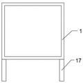
Fig. 1 is a structural diagram of a trimming device for a garden lawn according to the present invention;
fig. 2 is a schematic view of a grass thinning plate of the trimming device for the garden lawn of the present invention;
fig. 3 is a schematic diagram of a protection plate of the trimming device for the garden lawn of the present invention;
fig. 4 is the utility model provides a pruning device's that garden lawn used connector inside picture.
In the figure: the grass mowing machine comprises a machine body 1, a push handle 2, an adjusting screw rod 3, a connector 4, a mounting plate 5, a guide rod 6, a guide sleeve 7, a motor 8, a grass cutting wheel 9, a connecting rod 10, a positioning thread 11, a buffer spring 12, a connecting cylinder 13, a supporting plate 14, a grass thinning plate 15, a notch 16, a protection plate 17 and a rotating head 18.
Detailed Description
The technical solutions in the embodiments of the present invention will be described clearly and completely with reference to the accompanying drawings in the embodiments of the present invention, and it is obvious that the described embodiments are only some embodiments of the present invention, not all embodiments.
In the description of the present invention, it is to be understood that the terms "upper", "lower", "front", "rear", "left", "right", "top", "bottom", "inner", "outer", and the like indicate orientations or positional relationships based on the orientations or positional relationships shown in the drawings, and are only for convenience of description and simplicity of description, and do not indicate or imply that the device or element being referred to must have a particular orientation, be constructed and operated in a particular orientation, and therefore, should not be construed as limiting the present invention.
Referring to fig. 1-4, a pruning device for a garden lawn comprises a machine body 1, a push handle 2 is installed on one side of the machine body 1, two symmetrical guide rods 6 are installed in the machine body 1, guide sleeves 7 are slidably connected to the two guide rods 6, a mounting plate 5 is installed on the two guide sleeves 7, a motor 8 is installed on the mounting plate 5, a grass cutting wheel 9 is installed on an output shaft of the motor 8, a connecting rod is fixedly connected to the two guide sleeves 7, a connecting head 4 is installed at the upper end of the connecting rod, an adjusting screw rod 3 is installed on the connecting head 4, a grass thinning mechanism is installed at one end of the machine body 1 far away from the push handle 2, the grass thinning mechanism is used for combing planted grass and blocking objects such as large stones to avoid colliding with the grass cutting wheel 9 and flying out to hurt pedestrians, the safety of lawn pruning is ensured, the adjusting screw rod 3 is used for adjusting the height of the grass cutting wheel, thereby better controlling the thickness of the lawn mowing.
Specifically, the grass thinning mechanism comprises grass thinning plates 15, notches 16, connecting cylinders 13, supporting plates 14, buffer springs 12, connecting rods 10 and positioning threads 11, one end of the inner wall of the machine body 1, which is far away from the push plate, is fixedly connected with the supporting plate 14, the position of the machine body 1, which is positioned at the upper end of the supporting plate 14, is in threaded connection with the two connecting rods 10, the lower ends of the two connecting rods 10 are both fixedly connected with the connecting cylinders 13, the buffer springs 12 are installed in the connecting cylinders 13, guide rods are in sliding connection with the connecting cylinders 13, the grass thinning plates 15 are welded at the lower ends of the guide rods, the grass thinning plates 15 are respectively provided with a plurality of transversely arranged notches 16, the two connecting rods 10 are respectively provided with the two positioning threads 11, the grass planting plate 15 can comb the planted grass and block objects such as larger stones to avoid collision with the grass cutting wheel 9.
More specifically, a rotating groove is formed in the connecting head 4, and the rotating head 18 is welded at the lower end of the adjusting screw rod 3 and rotates in the rotating groove, so that the adjusting screw rod 3 only drives the connecting rod to move and does not rotate. The lower extreme of guide arm all passes backup pad 14, and the upper end of guide arm is located connecting cylinder 13 and has welded the anticreep head, and buffer spring 12 is located between anticreep head and the 13 inner walls of connecting cylinder, and organism 1 is all worn out to the upper end of connecting rod 10, receives the collision when grass thinning board 15 and can rise, drives guide arm extrusion buffer spring 12, then continues to reset. Grass cutting wheel 9 is located the lower extreme middle part of organism 1, and the equal fixedly connected with guard plate 17 in position that the lower extreme of organism 1 is located grass cutting wheel 9 both sides, and tiny stone and the collision departure of grass cutting wheel 9 can be avoided to guard plate 17. The position that organism 1 corresponds adjusting screw 3 installs the thread bush, and 3 threaded connection of adjusting screw are in the thread bush, and adjusting screw 3's upper end is worn out organism 1 and is welded and have the hand of changeing for adjusting screw 3 can sheathe in at the thread and remove.
The working principle is as follows: according to the thickness of the lawn vegetation, the height of the grass cutting wheel 9 is adjusted, the adjusting screw 3 can rotate, the adjusting screw 3 displaces on the threaded sleeve, the adjusting screw 3 rotates with the connector 4, so only the connecting rod and the guide sleeve 7 are driven to move, the height of the mounting plate 5 is adjusted, meanwhile, according to the planting type of the lawn, the corresponding grass cutting plate 15 is selected, the connecting rod 10 can be screwed, the positioning thread 11, close to the upper end, of the connecting rod 10 is fixed on the machine body 1, meanwhile, the positioning thread 11, close to the connecting cylinder 13, of the other connecting rod 10 is fixed on the machine body 1, the grass cutting plate 15 can comb the planting grass on the lawn, when the grass cutting plate collides with the obstacle, the grass cutting plate 15 can move upwards, the guide rod is driven to extrude the buffer spring 12, the damage to the grass cutting plate 15 can be reduced, meanwhile, objects such as stones can be blocked, and the grass cutting wheel 9 is prevented from colliding, the injury to the personnel is caused, and the protection plates 17 at the two ends of the machine body 1 can prevent fine stones from colliding with the mowing wheel 9 and flying out, so that the safety of lawn mowing is ensured.
The above, only be the concrete implementation of the preferred embodiment of the present invention, but the protection scope of the present invention is not limited thereto, and any person skilled in the art is in the technical scope of the present invention, according to the technical solution of the present invention and the utility model, the concept of which is equivalent to replace or change, should be covered within the protection scope of the present invention.
Claims (6)
1. The utility model provides a trimming means that garden lawn used, includes organism (1), its characterized in that, one side of organism (1) is installed and is pushed away (2), install two guide bars (6) of symmetry in organism (1), two equal sliding connection has uide bushing (7), two on guide bar (6) install mounting panel (5) jointly on uide bushing (7), install motor (8) on mounting panel (5), install grass cutting wheel (9), two on the output shaft of motor (8) common fixedly connected with connecting rod on uide bushing (7), connector (4) are installed to the connecting rod upper end, install adjusting screw (3) on connector (4), organism (1) is kept away from to push away the one end of (2) and is installed grass thinning mechanism.
2. The trimming device for the garden lawn according to claim 1, wherein the grass thinning mechanism comprises grass thinning plates (15), notches (16), connecting cylinders (13), supporting plates (14), buffer springs (12), connecting rods (10) and positioning threads (11), the supporting plate (14) is fixedly connected to one end of the inner wall of the machine body (1) far away from the pushing plate, two connecting rods (10) are connected to the position, located at the upper end of the supporting plate (14), of the machine body (1) in a threaded manner, the connecting cylinders (13) are fixedly connected to the lower ends of the two connecting rods (10), the buffer springs (12) are installed in the connecting cylinders (13), the guide rods are connected in the connecting cylinders (13) in a sliding manner, the grass thinning plates (15) are welded to the lower ends of the guide rods, and the grass thinning plates (15) are respectively provided with a plurality of transversely arranged notches (16), two positioning threads (11) are arranged on each of the two connecting rods (10).
3. The trimming device for garden lawns according to claim 1, wherein the connecting head (4) has a rotating groove therein, and the adjusting screw (3) has a rotating head (18) welded to the lower end thereof and rotates in the rotating groove.
4. The trimming device for garden lawns according to claim 2, wherein the lower ends of the guide rods pass through the support plate (14), the upper ends of the guide rods are positioned in the connecting cylinder (13) and welded with the anti-drop heads, the buffer springs (12) are positioned between the anti-drop heads and the inner wall of the connecting cylinder (13), and the upper ends of the connecting rods (10) all penetrate through the machine body (1).
5. The pruning device for garden lawns according to claim 1, wherein the grass cutting wheel (9) is located in the middle of the lower end of the machine body (1), and protection plates (17) are fixedly connected to the lower end of the machine body (1) at both sides of the grass cutting wheel (9).
6. The trimming device for garden lawns according to claim 1, wherein the body (1) is provided with a threaded sleeve corresponding to the position of the adjusting screw (3), the adjusting screw (3) is threaded in the threaded sleeve, and the upper end of the adjusting screw (3) penetrates through the body (1) and is welded with a rotating handle.
Priority Applications (1)
| Application Number | Priority Date | Filing Date | Title |
|---|---|---|---|
| CN201921885532.2U CN211020038U (en) | 2019-11-05 | 2019-11-05 | Trimming means that garden lawn used |
Applications Claiming Priority (1)
| Application Number | Priority Date | Filing Date | Title |
|---|---|---|---|
| CN201921885532.2U CN211020038U (en) | 2019-11-05 | 2019-11-05 | Trimming means that garden lawn used |
Publications (1)
| Publication Number | Publication Date |
|---|---|
| CN211020038U true CN211020038U (en) | 2020-07-17 |
Family
ID=71563575
Family Applications (1)
| Application Number | Title | Priority Date | Filing Date |
|---|---|---|---|
| CN201921885532.2U Active CN211020038U (en) | 2019-11-05 | 2019-11-05 | Trimming means that garden lawn used |
Country Status (1)
| Country | Link |
|---|---|
| CN (1) | CN211020038U (en) |
-
2019
- 2019-11-05 CN CN201921885532.2U patent/CN211020038U/en active Active
Similar Documents
| Publication | Publication Date | Title |
|---|---|---|
| US7117660B1 (en) | Self-propelled lawn mower | |
| CN207948158U (en) | A kind of grass trimmer of adjustable mowing height | |
| US6250056B1 (en) | Rotary blade pruning machine | |
| US6523337B2 (en) | SG pruning machine | |
| US2791875A (en) | Lawn mowing and trimming machine | |
| CN103404378A (en) | Hedgerow trimmer | |
| US7165382B2 (en) | Trimmer attachment for lawn mowers and tractors | |
| AU2021105205A4 (en) | A pruning machine with a cordon cutter | |
| CN211020038U (en) | Trimming means that garden lawn used | |
| CN212184190U (en) | Livestock-raising uses lawn mower convenient to adjust height of mowing | |
| CN209824519U (en) | Green belt trimmer | |
| US4747255A (en) | Cutter-bar support | |
| CN110800454A (en) | Mower with high trimming flatness and working method thereof | |
| CN208016354U (en) | A kind of multi-functional weeder suitable for garden landscape vegetation | |
| CN110199705A (en) | Hedgerow conical surface modeling scissors mechanism | |
| CN211378820U (en) | Mower with high trimming flatness | |
| AU2006100034B4 (en) | S G Pruning Machine for Clearing Windows of Vegetation | |
| CN108811673B (en) | Garden brush cutter | |
| CN210641434U (en) | Brush cutter with novel fender grass board | |
| CN213718741U (en) | Weeding robot and safety device thereof | |
| CN212367915U (en) | Unmanned mower | |
| CN213368696U (en) | Hand-push type multifunctional mower | |
| CN218789138U (en) | Hydraulic obstacle-avoiding mower | |
| CN109005994B (en) | Automatic trimming device for trimming garden shrubs | |
| CN219698475U (en) | Landscape construction ground mowing equipment |
Legal Events
| Date | Code | Title | Description |
|---|---|---|---|
| GR01 | Patent grant | ||
| GR01 | Patent grant |