CN211011663U - Air conditioner frame convenient to installation is dismantled - Google Patents
Air conditioner frame convenient to installation is dismantled Download PDFInfo
- Publication number
- CN211011663U CN211011663U CN201921923960.XU CN201921923960U CN211011663U CN 211011663 U CN211011663 U CN 211011663U CN 201921923960 U CN201921923960 U CN 201921923960U CN 211011663 U CN211011663 U CN 211011663U
- Authority
- CN
- China
- Prior art keywords
- frame
- air conditioner
- bar
- install
- easy
- Prior art date
- Legal status (The legal status is an assumption and is not a legal conclusion. Google has not performed a legal analysis and makes no representation as to the accuracy of the status listed.)
- Expired - Fee Related
Links
- 238000009434 installation Methods 0.000 title abstract description 9
- 238000004378 air conditioning Methods 0.000 claims description 2
- 239000003570 air Substances 0.000 description 19
- 238000010586 diagram Methods 0.000 description 3
- 230000005540 biological transmission Effects 0.000 description 2
- 239000012080 ambient air Substances 0.000 description 1
- 230000009286 beneficial effect Effects 0.000 description 1
- 238000005516 engineering process Methods 0.000 description 1
- 238000000034 method Methods 0.000 description 1
- 238000005057 refrigeration Methods 0.000 description 1
- XLYOFNOQVPJJNP-UHFFFAOYSA-N water Substances O XLYOFNOQVPJJNP-UHFFFAOYSA-N 0.000 description 1
Images


Landscapes
- Air Filters, Heat-Exchange Apparatuses, And Housings Of Air-Conditioning Units (AREA)
Abstract
本实用新型公开了一种便于安装拆卸的空调机架,包括架身,所述架身的两端表面中部开有限位槽,所述限位槽的顶端表面通过定位螺钉固定连接有条杆,所述架身的两端焊接有定位架,所述定位架的表面上方开有腰型孔,所述定位架的表面下方开有锁紧孔。该种实用新型通过设置有条杆、固定架、滑块、滑槽和调节槽,方便将空调外机架置在条杆和固定架上,空调外机上的锁紧片与调节槽表面相接触,滑块在滑槽内部进行移动,移动至锁紧片的正下方,此时通过安装螺钉贯穿锁紧片、调节槽与螺纹柱相接,再通过螺纹柱表面的内螺纹实现固定连接将放置在固定架上的锁紧片固定住,空调外机的另一端再通过安装螺钉穿入调节槽内部通过螺帽再进行紧固。
The utility model discloses an air conditioner rack which is easy to be installed and disassembled, comprising a frame body, a limit groove is formed in the middle of the two end surfaces of the frame body, and the top surface of the limit groove is fixedly connected with a bar through a positioning screw. The two ends of the frame body are welded with a positioning frame, the upper surface of the positioning frame is provided with a waist-shaped hole, and the lower surface of the positioning frame is provided with a locking hole. The utility model is provided with a bar, a fixing frame, a sliding block, a chute and an adjusting groove, so that the outer frame of the air conditioner is conveniently placed on the bar and the fixing frame, and the locking piece on the outer air conditioner is in contact with the surface of the adjusting groove. , the slider moves inside the chute and moves to just below the locking piece. At this time, the mounting screw penetrates the locking piece, the adjustment slot is connected to the threaded column, and then the internal thread on the surface of the threaded column is used to achieve a fixed connection. The locking piece on the fixing frame is fixed, and the other end of the outdoor unit of the air conditioner is then inserted into the adjustment groove through the installation screw and then fastened with the nut.
Description
技术领域technical field
本实用涉及空调装置技术领域,特别涉及一种便于安装拆卸的空调机架。The utility relates to the technical field of air conditioners, in particular to an air conditioner rack that is easy to install and disassemble.
背景技术Background technique
空调即空气调节器,是指用人工手段,对建筑或构筑物内环境空气的温度、湿度、流速等参数进行调节和控制的设备。An air conditioner is an air conditioner, which refers to a device that manually adjusts and controls the temperature, humidity, flow rate and other parameters of the ambient air in a building or structure.
一般包括冷源/热源设备,冷热介质输配系统,末端装置等几大部分和其他辅助设备。主要包括,制冷主机、水泵、风机和管路系统。末端装置则负责利用输配来的冷热量,具体处理空气状态,使目标环境的空气参数达到要求,现在对于空调外机的安装普遍都是装机工人一手拿空调机架另一手拿安装螺钉进行安装,这类安装方式不仅不方便且需要操作工人用机架紧贴墙面,安装起来较为费时费力。Generally, it includes cold source/heat source equipment, cold and hot medium transmission and distribution system, terminal devices and other auxiliary equipment. Mainly include, refrigeration host, water pump, fan and piping system. The terminal device is responsible for using the cold and heat from the transmission and distribution, specifically processing the air state, and making the air parameters of the target environment meet the requirements. Now, the installation of the air conditioner external unit is generally carried out by the assembler with the air conditioner rack in one hand and the installation screws in the other. Installation, this type of installation is not only inconvenient, but also requires operators to use the rack to stick to the wall, which is time-consuming and labor-intensive to install.
实用新型内容Utility model content
本实用新型的主要目的在于提供一种便于安装拆卸的空调机架,可以有效解决背景技术中的问题。The main purpose of the present invention is to provide an air conditioner rack that is easy to install and disassemble, which can effectively solve the problems in the background technology.
为实现上述目的,本实用新型采取的技术方案为:To achieve the above purpose, the technical scheme adopted by the present utility model is:
一种便于安装拆卸的空调机架,包括架身,所述架身的两端表面中部开有限位槽,所述限位槽的顶端表面通过定位螺钉固定连接有条杆,所述架身的两端焊接有定位架,所述定位架的表面上方开有腰型孔,所述定位架的表面下方开有锁紧孔,所述定位架与墙体紧密相接,所述架身的一端表面焊接有固定架,所述固定架的内部开有滑槽,所述滑槽的内部两端滑动连接有滑块,所述固定架和条杆的顶端两端开有调节槽,所述滑块底端中部固定连接有螺纹柱,所述螺纹柱的内部设置有内螺纹。An air conditioner rack that is easy to install and disassemble, including a frame body, a limit groove is opened in the middle of the surface of both ends of the frame body, and a top surface of the limit groove is fixedly connected with a bar through positioning screws, and the Both ends are welded with a positioning frame, a waist-shaped hole is opened above the surface of the positioning frame, a locking hole is opened under the surface of the positioning frame, the positioning frame is closely connected with the wall, and one end of the frame body is A fixing frame is welded on the surface, a chute is opened inside the fixing frame, a sliding block is slidably connected to the inner two ends of the sliding groove, and the top ends of the fixing frame and the bar are provided with adjustment grooves, and the sliding groove is The middle part of the bottom end of the block is fixedly connected with a threaded column, and the interior of the threaded column is provided with an internal thread.
进一步地,所述腰型孔的底端孔的直径大于顶端孔的直径,所述腰型孔关于架身对称分布。Further, the diameter of the bottom hole of the waist-shaped hole is larger than the diameter of the top hole, and the waist-shaped holes are symmetrically distributed with respect to the frame body.
进一步地,所述滑块为可拆卸结构,所述滑块呈书钉状结构,所述滑块与滑槽间隙配合。Further, the sliding block is a detachable structure, the sliding block is a staple-like structure, and the sliding block is in clearance fit with the chute.
进一步地,所述螺纹柱呈圆柱状结构,所述螺纹柱的内部为空心结构,所述螺纹柱设置在滑块的中部正下方。Further, the threaded column has a cylindrical structure, the interior of the threaded column is a hollow structure, and the threaded column is arranged just below the middle of the slider.
进一步地,所述调节槽均匀分布在条杆和固定架的两端,所述调节槽关于条杆和固定架对称分布。Further, the adjusting grooves are evenly distributed on both ends of the bar and the fixing frame, and the adjusting grooves are symmetrically distributed with respect to the bar and the fixing frame.
进一步地,所述条杆与固定架的高度相同,所述条杆为可拆卸结构。Further, the height of the bar is the same as that of the fixing frame, and the bar is a detachable structure.
进一步地,所述限位槽贯穿架身的内部,所述限位槽在架身的表面至少设置有两条。Further, the limiting grooves run through the inside of the frame body, and at least two limiting grooves are provided on the surface of the frame body.
与现有技术相比,本实用新型具有如下有益效果:Compared with the prior art, the utility model has the following beneficial effects:
(1):该种实用新型通过设置有定位架、腰型孔和锁紧孔,方便先测量两端腰型孔之间的距离再在墙体表面做好标记,然后在墙体表面做好标记处打孔安装螺钉,再将定位架两端的腰型孔挂在螺钉上,此时,操作工人用手将定位架的表面紧贴墙体表面,在锁紧孔处打孔安装锁紧螺钉,便于将整个定位架和架身进行固定;(1): This utility model is provided with a positioning frame, a waist-shaped hole and a locking hole, so that it is convenient to measure the distance between the waist-shaped holes at both ends, and then mark on the surface of the wall, and then make a mark on the surface of the wall. Drill holes at the marked places to install screws, and then hang the waist-shaped holes at both ends of the positioning frame on the screws. At this time, the operator presses the surface of the positioning frame against the wall surface by hand, and punches holes at the locking holes to install the locking screws. , it is convenient to fix the whole positioning frame and frame body;
(2):该种实用新型通过设置有条杆、固定架、滑块、滑槽和调节槽,方便将空调外机架置在条杆和固定架上,空调外机上的锁紧片与调节槽表面相接触,滑块在滑槽内部进行移动,移动至锁紧片的正下方,此时通过安装螺钉贯穿锁紧片、调节槽与螺纹柱相接,再通过螺纹柱表面的内螺纹实现固定连接将放置在固定架上的锁紧片固定住,空调外机的另一端再通过安装螺钉穿入调节槽内部通过螺帽再进行紧固。(2): The utility model is provided with a bar, a fixing frame, a slider, a chute and an adjusting groove, so that the outer frame of the air conditioner is conveniently placed on the bar and the fixing frame, and the locking piece on the outer air conditioner is adjusted to The surface of the groove is in contact, and the slider moves inside the chute and moves to just below the locking piece. At this time, the mounting screw penetrates the locking piece, the adjustment groove is connected to the threaded column, and then the internal thread on the surface of the threaded column is used to realize the The fixed connection fixes the locking piece placed on the fixing frame, and the other end of the air conditioner outdoor unit is then inserted into the adjustment groove through the installation screw and then tightened by the nut.
附图说明Description of drawings
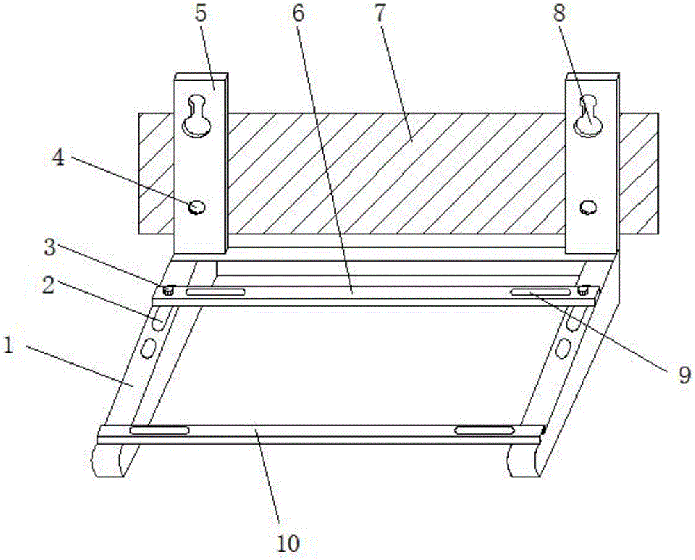
图1为本实用新型的整体的结构示意图。FIG. 1 is a schematic diagram of the overall structure of the present invention.
图2为本实用新型的固定架的局部结构示意图。FIG. 2 is a partial structural schematic diagram of the fixing frame of the present invention.
图3为本实用新型的滑块的整体结构示意图。3 is a schematic diagram of the overall structure of the slider of the present invention.
图4为本实用新型的滑块的左视图。FIG. 4 is a left side view of the slider of the present invention.
图中:1、架身;2、限位槽;3、定位螺钉;4、锁紧孔;5、定位架;6、条杆;7、墙体;8、腰型孔;9、调节槽;10、固定架;11、滑块;12、螺纹柱;13、内螺纹;14、滑槽。In the figure: 1. Frame; 2. Limit slot; 3. Positioning screw; 4. Locking hole; 5. Positioning frame; 6. Bar; 7. Wall; 8. Waist hole; 9. Adjustment slot ; 10, fixed frame; 11, slider; 12, threaded column; 13, internal thread; 14, chute.
具体实施方式Detailed ways
为使本实用新型实现的技术手段;创作特征;达成目的与功效易于明白了解,下面结合具体实施方式,进一步阐述本实用新型。In order to make the technical means, creative features, and achievement of the present utility model easy to understand and understand, the present utility model will be further described below with reference to the specific embodiments.
如图1-4所示,一种便于安装拆卸的空调机架,包括架身1,所述架身1的两端表面中部开有限位槽2,所述限位槽2的顶端表面通过定位螺钉3固定连接有条杆6,所述架身1的两端焊接有定位架5,所述定位架5的表面上方开有腰型孔8,所述定位架5的表面下方开有锁紧孔4,所述定位架5与墙体7紧密相接,所述架身1的一端表面焊接有固定架10,所述固定架10的内部开有滑槽14,所述滑槽14的内部两端滑动连接有滑块11,所述固定架10和条杆6的顶端两端开有调节槽9,所述滑块11底端中部固定连接有螺纹柱12,所述螺纹柱12的内部设置有内螺纹13。As shown in Figures 1-4, an air conditioner rack that is easy to install and disassemble includes a
其中,所述腰型孔8的底端孔的直径大于顶端孔的直径,所述腰型孔8关于架身1对称分布。Wherein, the diameter of the bottom hole of the waist-
其中,所述滑块11为可拆卸结构,所述滑块11呈书钉状结构,所述滑块11与滑槽14间隙配合,通过滑块11在滑槽14内部移动,便于根据不同的位置对空调外机进行安装固定。The
其中,所述螺纹柱12呈圆柱状结构,所述螺纹柱12的内部为空心结构,所述螺纹柱12设置在滑块11的中部正下方。The threaded
其中,所述调节槽9均匀分布在条杆6和固定架10的两端,所述调节槽9关于条杆6和固定架10对称分布。The adjusting grooves 9 are evenly distributed on both ends of the
其中,所述条杆6与固定架10的高度相同,所述条杆6为可拆卸结构。The height of the
其中,所述限位槽2贯穿架身1的内部,所述限位槽2在架身1的表面至少设置有两条。Wherein, the
需要说明的是,本实用新型为一种便于安装拆卸的空调机架,在使用过程中,首先,测量两端腰型孔8之间的距离,在墙体7表面做好记号,再在墙体7表面做好记号处打入安装螺钉,将定位架5两端的腰型孔8套挂在安装螺钉上,此时,定位架5和架身1悬挂在安装螺钉上,操作人员用手将定位架5紧贴墙体7,再在锁紧孔4处打入螺纹,对定位架5和架身1实现固定安装,通过定位螺钉3插入限位槽2内部通过螺帽将条杆6固定连接,空调外机的底端两端放置在条杆6和固定架10表面,空调外机靠近固定架10的底端两端锁紧片放置在固定架10两端的调节槽9上,通过滑块11在滑槽14内部滑动,使得滑块11移动至调节槽9处,安装螺钉贯穿锁紧片、调节槽9与螺纹柱12相接,再旋入内螺纹13内部实现固定,空调外机底端架置在条杆6两端通过安装螺钉穿入锁紧片和调节槽9再通过螺帽进行固定连接,实现对空调外机的固定。It should be noted that the utility model is an air-conditioning rack that is easy to install and disassemble. During use, first, measure the distance between the waist-
以上显示和描述了本实用新型的基本原理和主要特征和本实用新型的优点。本行业的技术人员应该了解,本实用新型不受上述实施例的限制,上述实施例和说明书中描述的只是说明本实用新型的原理,在不脱离本实用新型精神和范围的前提下,本实用新型还会有各种变化和改进,这些变化和改进都落入要求保护的本实用新型范围内。本实用新型要求保护范围由所附的权利要求书及其等效物界定。The basic principles and main features of the present invention and the advantages of the present invention are shown and described above. It should be understood by those skilled in the art that the present invention is not limited by the above-mentioned embodiments. The above-mentioned embodiments and descriptions only illustrate the principle of the present invention. Without departing from the spirit and scope of the present invention, the present invention There will also be various changes and improvements in the new model, which all fall within the scope of the claimed invention. The claimed scope of the present invention is defined by the appended claims and their equivalents.
Claims (7)
Priority Applications (1)
| Application Number | Priority Date | Filing Date | Title |
|---|---|---|---|
| CN201921923960.XU CN211011663U (en) | 2019-11-09 | 2019-11-09 | Air conditioner frame convenient to installation is dismantled |
Applications Claiming Priority (1)
| Application Number | Priority Date | Filing Date | Title |
|---|---|---|---|
| CN201921923960.XU CN211011663U (en) | 2019-11-09 | 2019-11-09 | Air conditioner frame convenient to installation is dismantled |
Publications (1)
| Publication Number | Publication Date |
|---|---|
| CN211011663U true CN211011663U (en) | 2020-07-14 |
Family
ID=71507762
Family Applications (1)
| Application Number | Title | Priority Date | Filing Date |
|---|---|---|---|
| CN201921923960.XU Expired - Fee Related CN211011663U (en) | 2019-11-09 | 2019-11-09 | Air conditioner frame convenient to installation is dismantled |
Country Status (1)
| Country | Link |
|---|---|
| CN (1) | CN211011663U (en) |
-
2019
- 2019-11-09 CN CN201921923960.XU patent/CN211011663U/en not_active Expired - Fee Related
Similar Documents
| Publication | Publication Date | Title |
|---|---|---|
| CN211011663U (en) | Air conditioner frame convenient to installation is dismantled | |
| CN217817046U (en) | Wall-mounted air conditioner installation assembly | |
| CN216286212U (en) | Intelligent building air conditioner energy-saving monitoring device | |
| CN208399051U (en) | A kind of temperature-detecting device of easy-to-dismount heat insulating coatings | |
| CN217385300U (en) | A kind of building door and window thermal insulation performance testing equipment | |
| CN207528582U (en) | A kind of aluminium flake frosting performance testing device | |
| CN208063635U (en) | A kind of data analysis equipment radiator being easily installed | |
| CN216790368U (en) | Novel inside anti-cold bridge insulation construction of machine in air conditioning | |
| CN207178899U (en) | A kind of channel bend supporting construction | |
| CN109442719A (en) | Central air-conditioning outlet air guide frame | |
| CN211876197U (en) | A safety fixing device applied to the installation of HVAC outdoor units | |
| CN211119727U (en) | Air conditioner external unit support frame capable of avoiding condensed water accumulation | |
| CN221924202U (en) | Air curtain cabinet air curtain debugging device | |
| CN210772523U (en) | Novel air conditioner mounting bracket with adjustable easy dismouting | |
| CN210486032U (en) | Adjustable hanging rack of central air conditioner indoor unit | |
| CN219656196U (en) | Air conditioner fixing mounting frame | |
| CN111829162A (en) | A self-assembled central air conditioning system positioning device | |
| CN222103882U (en) | A central air conditioning duct installation hanger | |
| CN219084803U (en) | Light plastering gypsum construction variable performance inspection box | |
| CN218935469U (en) | Intelligent balance valve containing energy meter and used for hydraulic balance of heating ventilation air conditioner | |
| CN205425353U (en) | Cloth wind ware with adjustable cloth wind dish | |
| CN213480399U (en) | Free ceiling type air conditioner | |
| CN219160490U (en) | Air conditioner support convenient to adjust | |
| CN219868424U (en) | Direction-adjustable air deflector of air conditioner | |
| CN220152910U (en) | Air conditioner air pipe orifice capable of evenly discharging air |
Legal Events
| Date | Code | Title | Description |
|---|---|---|---|
| GR01 | Patent grant | ||
| GR01 | Patent grant | ||
| TR01 | Transfer of patent right | ||
| TR01 | Transfer of patent right |
Effective date of registration: 20230602 Address after: 214000 Huaqing Chuangzhi Park 8-603-1, Huishan Economic Development Zone, Wuxi City, Jiangsu Province Patentee after: Wuxi Zhaojian Mechanical and Electrical Installation Co.,Ltd. Address before: 336000 no.6-2, Jieshang group, Songbu village, Songbu Town, Fengxin County, Yichun City, Jiangxi Province Patentee before: Song Fangfang |
|
| CF01 | Termination of patent right due to non-payment of annual fee | ||
| CF01 | Termination of patent right due to non-payment of annual fee |
Granted publication date: 20200714 |