CN210952262U - Scale graphite drying device - Google Patents
Scale graphite drying device Download PDFInfo
- Publication number
- CN210952262U CN210952262U CN201922025349.1U CN201922025349U CN210952262U CN 210952262 U CN210952262 U CN 210952262U CN 201922025349 U CN201922025349 U CN 201922025349U CN 210952262 U CN210952262 U CN 210952262U
- Authority
- CN
- China
- Prior art keywords
- drying
- fixedly connected
- box
- driving motor
- drying device
- Prior art date
- Legal status (The legal status is an assumption and is not a legal conclusion. Google has not performed a legal analysis and makes no representation as to the accuracy of the status listed.)
- Active
Links
Images

Abstract
The utility model discloses a scale graphite drying device, including the drying cabinet, the upside fixedly connected with delivery box of drying cabinet, the upside fixedly connected with feeder hopper of delivery box, be provided with the feed inlet between feeder hopper and the delivery box, the lateral wall fixedly connected with driving motor of delivery box, driving motor's output shaft end extends to the inside and the fixedly connected with pivot of delivery box, the cover is equipped with the spiral delivery leaf in the pivot, and both fixed connection, the one end that driving motor was kept away from in the pivot extends to the outside of delivery box. The utility model has the advantages of reasonable design, can carry out the at the uniform velocity feeding with the material, prevent that the condition of jam from appearing in the material, at dry in-process, still turn the material to abundant dry material can guarantee the drying effect of material, and heatable water when steam discharges improves the utilization ratio of hot gas flow, reduces the waste of the energy.
Description
Technical Field
The utility model relates to a graphite drying device technical field especially relates to a scale graphite drying device.
Background
The flake graphite is natural aphanitic graphite which is shaped like fish phosphorus, belongs to a hexagonal system, is in a layered structure and has good performances of high temperature resistance, electric conduction, heat conduction, lubrication, plasticity, acid and alkali resistance and the like. The flake graphite is a natural solid lubricant with a layered structure, is rich in resources and low in price
During the processing of flake graphite, the drying of graphite in the pretreatment of raw materials or the post-treatment stage of products is indispensable. The existing graphite drying equipment is generally single in structure, and the graphite material cannot be fully dried during drying, so that the drying efficiency of the material is not high, and the processing quality of the material is even affected.
SUMMERY OF THE UTILITY MODEL
The utility model aims at solving the shortcoming that exists among the prior art, and the scale graphite drying device who provides, it can carry out the at the uniform velocity feeding with the material, prevents that the condition of jam from appearing in the material, at dry in-process, still turns the material to abundant dry material can guarantee the drying effect of material, and heatable water when steam discharges improves the utilization ratio of hot gas flow, reduces the waste of the energy.
In order to achieve the above purpose, the utility model adopts the following technical scheme:
a flake graphite drying device comprises a drying box, wherein a conveying box is fixedly connected to the upper side of the drying box, a feeding hopper is fixedly connected to the upper side of the conveying box, a feeding port is arranged between the feeding hopper and the conveying box, a driving motor is fixedly connected to the side wall of the conveying box, the tail end of an output shaft of the driving motor extends into the conveying box and is fixedly connected with a rotating shaft, a spiral conveying blade is sleeved on the rotating shaft and is fixedly connected with the spiral conveying blade, one end, far away from the driving motor, of the rotating shaft extends to the outer side of the conveying box, a rotatable rotating rod is arranged in the drying box, a plurality of turning blades are arranged on the outer side of the rotating rod at equal intervals, one end of the rotating rod extends to the outer portion of the drying box, the rotating rod is in transmission connection with the rotating shaft through a transmission mechanism, and a, the upside of drying cabinet is provided with the exhaust pipe, the inside of exhaust pipe is provided with the filter screen, the outside cover of exhaust pipe is equipped with heating mechanism, the downside of drying cabinet is provided with the discharge gate.
Preferably, the transmission mechanism comprises two transmission wheels which are respectively and fixedly connected to the rotating shaft and the left end of the rotating rod, and the two transmission wheels are in transmission connection through a transmission belt.
Preferably, a discharge opening is arranged between the conveying box and the drying box and is positioned at the upper left end position of the drying box.
Preferably, the hot air mechanism comprises a hot air generator fixedly connected to the lower side of the drying box, an annular plate is fixedly connected to the left side of the drying box, an inner cavity is formed in the annular plate, a plurality of air outlets which are communicated are formed in the circumferential direction between the inner cavity and the drying box at equal intervals, and the annular plate and the hot air generator are connected through a communicating pipe.
Preferably, heating mechanism is equipped with the heating jacket in the exhaust pipe outside including the cover, and both fixed connection, the inside of heating jacket is provided with the heating runner, the end of intaking and the play water end of heating runner all are provided with the joint.
Preferably, the heating flow channel has a spiral structure.
The utility model discloses possess following beneficial effect:
1. the rotating shaft is driven to rotate by the driving motor, so that materials can be fed at a constant speed by the spiral conveying blade, the blockage during feeding is avoided, the drying effect can be improved, meanwhile, the rotating rod and the rotating shaft synchronously rotate through the transmission mechanism, the materials can be turned by turning the blade, and the materials can be sufficiently dried;
2. the filter screen is used for filtering in the discharging process, so that air pollution is avoided, and in the discharging process, the heat in the hot air flow can heat the water in the heating flow channel, so that the utilization rate of the hot air flow is improved, and the waste of energy is reduced.
Drawings
Fig. 1 is a schematic sectional structure diagram of an flake graphite drying device according to the present invention;
fig. 2 is a schematic front view of the flake graphite drying device according to the present invention.
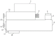
In the figure: the device comprises a feed hopper 1, a drive motor 2, an exhaust pipe 3, a filter screen 4, a heating jacket 5, a drying box 6, an overturning blade 7, a rotating rod 8, a discharge port 9, a hot air generator 10, a communicating pipe 11, an annular plate 12, a driving wheel 13, an inner cavity 14, a driving belt 15, an air outlet 16, a rotating shaft 17, a spiral conveying blade 18, a feed inlet 19, a heating flow channel 20 and a conveying box 21.
Detailed Description
The technical solutions in the embodiments of the present invention will be described clearly and completely with reference to the accompanying drawings in the embodiments of the present invention, and it is obvious that the described embodiments are only some embodiments of the present invention, not all embodiments.
In the description of the present invention, it is to be understood that the terms "upper", "lower", "front", "rear", "left", "right", "top", "bottom", "inner", "outer", and the like indicate orientations or positional relationships based on the orientations or positional relationships shown in the drawings, and are only for convenience of description and simplicity of description, and do not indicate or imply that the device or element being referred to must have a particular orientation, be constructed and operated in a particular orientation, and therefore, should not be construed as limiting the present invention.
Referring to fig. 1-2, a flake graphite drying device comprises a drying box 6, a conveying box 21 is fixedly connected to the upper side of the drying box 6, a feeding hopper 1 is fixedly connected to the upper side of the conveying box 21, a feeding port 19 is arranged between the feeding hopper 1 and the conveying box 21, a driving motor 2 is fixedly connected to the side wall of the conveying box 21, the tail end of an output shaft of the driving motor 2 extends into the conveying box 21 and is fixedly connected with a rotating shaft 17, a spiral conveying blade 18 is sleeved on the rotating shaft 17 and is fixedly connected with the same, one end of the rotating shaft 17 far away from the driving motor 2 extends to the outer side of the conveying box 21, a rotatable rotating rod 8 is arranged in the drying box 6, a plurality of turning blades 7 are arranged at equal intervals outside of the rotating rod 8, one end of the rotating rod 8 extends to the outside of the drying box 6, the rotating rod 8 is in transmission connection with the rotating shaft 17 through a, the upside of drying cabinet 6 is provided with exhaust pipe 3, and the inside of exhaust pipe 3 is provided with filter screen 4, and the outside cover of exhaust pipe 3 is equipped with heating mechanism, and the downside of drying cabinet 6 is provided with discharge gate 9, is provided with the bin outlet between delivery box 21 and the drying cabinet 6, and the bin outlet is located the upside left end position of drying cabinet 6.
Specifically, the transmission mechanism comprises two transmission wheels 13 fixedly connected to the left ends of the rotating shaft 17 and the rotating rod 8 respectively, and the two transmission wheels 13 are in transmission connection through a transmission belt 15, so that the rotating rod 8 and the rotating shaft 17 can rotate synchronously.
Specifically, hot-blast mechanism includes hot-blast generator 10 of fixed connection in the drying cabinet 6 downside, the left side fixedly connected with annular plate 12 of drying cabinet 6, the inside of annular plate 12 is provided with inner chamber 14, the equidistant a plurality of air outlets 16 that are provided with the link up of circumference between inner chamber 14 and the drying cabinet 6, connect through communicating pipe 11 between annular plate 12 and the hot-blast generator 10, this structure produces the hot air current through the operation of hot-blast generator 10 and can heat drying process the material.
The hot wind generator 10 is prior art and does not do too much of the wart here.
Specifically, heating mechanism is including the cover being equipped with heating jacket 5 in the exhaust pipe 3 outside, and both fixed connection, and the inside of heating jacket 5 is provided with heating runner 20, and heating runner 20's the end of intaking and the end of play water all are provided with the joint, and heating runner 20 is the heliciform structure, utilizes the heat in the hot gas stream to carry out the heat treatment to the water in the heating runner 20, improves the utilization ratio of hot gas stream, reduces the waste of the energy.
When the drying device works, firstly, materials are put into the feeding hopper 1, the driving motor 2 is started, the output shaft of the driving motor 2 rotates to drive the rotating shaft 17 to rotate, the rotating shaft 17 rotates to drive the spiral conveying blade 18 to rotate, so that the materials can be fed at a constant speed and enter the drying box 6 through the discharge hole, the hot air generator 10 is utilized to generate hot air, the hot air enters the inner cavity 14 of the annular plate 12 through the communicating hole 11 and is sprayed out through the air outlet 16, the materials can be dried, in the rotating process of the rotating shaft 17, the rotating rod 8 rotates through the matching between the two driving wheels 13 and the driving belt 15, so that the turning blade 7 can rotate, the materials can be turned conveniently, the drying effect is improved, the dried materials can be discharged through the discharge hole 9 under the action of the hot air, the hot air can be discharged through the exhaust pipe 3, and can be filtered through the filter screen 4 in the, the pollution of air is avoided, and in the discharging process, the heat in the hot air flow can heat the water in the heating flow channel 20, so that the utilization rate of the hot air flow is improved, and the waste of energy is reduced.
Above, only be the concrete implementation of the preferred embodiment of the present invention, but the protection scope of the present invention is not limited thereto, and any person skilled in the art is in the technical scope of the present invention, according to the technical solution of the present invention and the design of the present invention, equivalent replacement or change should be covered within the protection scope of the present invention.
Claims (6)
1. The flake graphite drying device comprises a drying box (6) and is characterized in that a conveying box (21) is fixedly connected to the upper side of the drying box (6), a feeding hopper (1) is fixedly connected to the upper side of the conveying box (21), a feeding port (19) is formed between the feeding hopper (1) and the conveying box (21), a driving motor (2) is fixedly connected to the side wall of the conveying box (21), the tail end of an output shaft of the driving motor (2) extends into the conveying box (21) and is fixedly connected with a rotating shaft (17), a spiral conveying blade (18) is sleeved on the rotating shaft (17) and is fixedly connected with the rotating shaft (17), one end, far away from the driving motor (2), of the rotating shaft (17) extends to the outer side of the conveying box (21), a rotatable rotating rod (8) is arranged inside the drying box (6), a plurality of turning blades (7) are arranged on the outer side of the rotating rod (8) at equal intervals, the one end of dwang (8) extends to the outside of drying cabinet (6), connect through the drive mechanism transmission between dwang (8) and pivot (17), the outside of drying cabinet (6) is provided with the hot-blast mechanism that is used for drying, the upside of drying cabinet (6) is provided with exhaust pipe (3), the inside of exhaust pipe (3) is provided with filter screen (4), the outside cover of exhaust pipe (3) is equipped with heating mechanism, the downside of drying cabinet (6) is provided with discharge gate (9).
2. Flake graphite drying device according to claim 1, characterized in that the transmission mechanism comprises two transmission wheels (13) fixedly connected to the rotation shaft (17) and the left end of the rotation lever (8), respectively, the two transmission wheels (13) being in transmission connection with each other via a transmission belt (15).
3. Flake graphite drying device according to claim 1, characterized in that a discharge opening is provided between the delivery box (21) and the drying box (6), said discharge opening being located at the upper left end position of the drying box (6).
4. The flake graphite drying device according to claim 1, wherein the hot air mechanism comprises a hot air generator (10) fixedly connected to the lower side of the drying box (6), an annular plate (12) is fixedly connected to the left side of the drying box (6), an inner cavity (14) is arranged inside the annular plate (12), a plurality of through air outlets (16) are circumferentially arranged between the inner cavity (14) and the drying box (6) at equal intervals, and the annular plate (12) and the hot air generator (10) are connected through a communication pipe (11).
5. The flake graphite drying device according to claim 1, wherein the heating mechanism comprises a heating sleeve (5) sleeved outside the exhaust pipe (3) and fixedly connected with the exhaust pipe, a heating flow channel (20) is arranged inside the heating sleeve (5), and a joint is arranged at both a water inlet end and a water outlet end of the heating flow channel (20).
6. Flake graphite drying device according to claim 5, characterized in that the heating channel (20) is of a helical structure.
Priority Applications (1)
| Application Number | Priority Date | Filing Date | Title |
|---|---|---|---|
| CN201922025349.1U CN210952262U (en) | 2019-11-21 | 2019-11-21 | Scale graphite drying device |
Applications Claiming Priority (1)
| Application Number | Priority Date | Filing Date | Title |
|---|---|---|---|
| CN201922025349.1U CN210952262U (en) | 2019-11-21 | 2019-11-21 | Scale graphite drying device |
Publications (1)
| Publication Number | Publication Date |
|---|---|
| CN210952262U true CN210952262U (en) | 2020-07-07 |
Family
ID=71389909
Family Applications (1)
| Application Number | Title | Priority Date | Filing Date |
|---|---|---|---|
| CN201922025349.1U Active CN210952262U (en) | 2019-11-21 | 2019-11-21 | Scale graphite drying device |
Country Status (1)
| Country | Link |
|---|---|
| CN (1) | CN210952262U (en) |
Cited By (1)
| Publication number | Priority date | Publication date | Assignee | Title |
|---|---|---|---|---|
| CN113580418A (en) * | 2021-06-17 | 2021-11-02 | 安徽艾雅伦新材料科技有限公司 | Drying device is used in processing of PVC substrate |
-
2019
- 2019-11-21 CN CN201922025349.1U patent/CN210952262U/en active Active
Cited By (1)
| Publication number | Priority date | Publication date | Assignee | Title |
|---|---|---|---|---|
| CN113580418A (en) * | 2021-06-17 | 2021-11-02 | 安徽艾雅伦新材料科技有限公司 | Drying device is used in processing of PVC substrate |
Similar Documents
| Publication | Publication Date | Title |
|---|---|---|
| CN207546669U (en) | It is pulverized and mixed coal briquette processing drying unit | |
| CN207688530U (en) | A kind of centrifugal energy saving feed drying device | |
| CN210952262U (en) | Scale graphite drying device | |
| CN105084707A (en) | Sludge fragmentation-type drying device | |
| CN201667980U (en) | Airflow stirring curing conditioner | |
| CN101900479B (en) | Poultry excrement drying device | |
| CN208254140U (en) | A kind of drying conveying device based on nanometer calcium carbonate wet feed | |
| CN213363269U (en) | Energy-saving grain conveying special drying fan | |
| CN213514821U (en) | Flash evaporation dryer for rapidly drying clostridium butyricum viable bacteria preparation | |
| CN204310939U (en) | sludge heat drying device | |
| CN108174706A (en) | A kind of portable stalk crushes drying device | |
| CN204714677U (en) | The rotor drying equipment that anti-mud hardens | |
| CN208223121U (en) | A kind of multiple-element long active composite heat transfer dryer | |
| CN112503889A (en) | Composite particle drying device | |
| CN208574682U (en) | A kind of grinding device of synthetic rubber raw material | |
| CN207600116U (en) | A kind of suspended state breaks up dryer | |
| CN111250241B (en) | Feed milk powder drying device | |
| CN204310934U (en) | Sludge crushing formula drying equipment | |
| CN220582982U (en) | Organic fertilizer production roller drying device | |
| CN204714678U (en) | Reverse-flow mud drying device | |
| CN219637076U (en) | Sludge waste heat drying device | |
| CN217967756U (en) | Mixer for plastics processing | |
| CN219607643U (en) | Raw material drying device for woven bag production | |
| CN111322856B (en) | Dihydrate gypsum drying device | |
| CN214842208U (en) | Airflow dryer for chitin production |
Legal Events
| Date | Code | Title | Description |
|---|---|---|---|
| GR01 | Patent grant | ||
| GR01 | Patent grant |