CN210937726U - Over-and-under type exchange platform for laser cutting machine - Google Patents
Over-and-under type exchange platform for laser cutting machine Download PDFInfo
- Publication number
- CN210937726U CN210937726U CN201921429282.1U CN201921429282U CN210937726U CN 210937726 U CN210937726 U CN 210937726U CN 201921429282 U CN201921429282 U CN 201921429282U CN 210937726 U CN210937726 U CN 210937726U
- Authority
- CN
- China
- Prior art keywords
- guide rail
- workbench
- cutting machine
- laser cutting
- exchange platform
- Prior art date
- Legal status (The legal status is an assumption and is not a legal conclusion. Google has not performed a legal analysis and makes no representation as to the accuracy of the status listed.)
- Active
Links
Images


Abstract
The utility model discloses a lifting exchange platform for a laser cutting machine, which comprises a supporting frame, a lifting driving unit arranged on the supporting frame, a guide rail unit driven by the lifting driving unit to move up and down, a first workbench and a second workbench which horizontally slide on the guide rail unit and are distributed in an up-and-down laminated manner, and a cutting scrap collecting box which is arranged at the bottom of the supporting frame and is used for collecting cutting scraps, the lifting driving unit is provided with two groups of front and rear parts which are positioned on the supporting frames and comprise a rotary shaft which is rotatably erected between the supporting frames, a servo driving part which drives the rotary shaft to rotate, driving sprockets which are fixed at two ends of the rotary shaft, driven sprockets which realize transmission through chains and the driving sprockets, and connecting plates which are fixed on the chains, wherein the connecting plates are fixedly connected with the guide rail unit. The utility model provides high stability, the platform positional stability that the platform goes up and down.
Description
[ technical field ] A method for producing a semiconductor device
The utility model belongs to the technical field of special type processing laser cutting, especially, relate to an over-and-under type exchange platform for laser cutting machine.
[ background of the invention ]
The laser cutting is used as a special processing means, the main principle is that high-power density energy generated after laser generated by a laser is focused under an optical path system is used for cutting off materials, the laser cutting device can be widely applied to processing of various metals such as carbon steel, manganese steel, stainless steel, galvanized plates, aluminum plates, copper plates and the like, and the laser cutting device has the advantages of being narrow in cut, small in heat affected zone, smooth in cut and capable of cutting any shape.
Traditional single platform laser cutting machine, after the steel sheet was accomplished in the cutting on the workstation, needed the machine to stop the cutting to move to the machine rear end, operating personnel took off the work piece that the cutting was good from the workstation this moment totally, and cleared up the tails, wait that the clean-up just can transport new panel to the workstation on, then began the cutting. The process of unloading and clearance tails consuming time longer in this period, and the cutting machine must be in the shutdown state this moment, and serious waste time has greatly reduced cutting efficiency.
Some exchange type double working platforms are also developed in the prior art to realize automatic replacement, but certain defects exist in the lifting stability of the working platform, for example, patent application No. 201720355884.1 discloses a working platform lifting exchange type laser cutting machine, the lifting of which is realized by adopting an oil cylinder, and the phenomenon that a workpiece placed on the working platform is bumpy or bounced and shifted is easily caused by instant pause and contusion impact during the lifting process; when the working platform is positioned at a feeding or discharging position, no fixed guarantee measures are provided, so that the sliding of the working platform in the process of feeding and discharging workpieces is easy to influence the working platform being processed; in the feeding and discharging process, a large number of machining chips are remained on the working platform, the machining chips are scattered below the exchange type platform to cause a messy phenomenon, and the machining chips can fall into a platform guide rail to cause the platform to be blocked seriously.
Therefore, a new lift type exchange platform for a laser cutting machine is needed to solve the above problems.
[ Utility model ] content
A primary object of the utility model is to provide a laser cutting machine is with over-and-under type exchange platform has improved the stability, the platform positional stability that the platform goes up and down.
The utility model discloses a following technical scheme realizes above-mentioned purpose: the lifting type exchange platform for the laser cutting machine comprises a supporting frame, a lifting driving unit arranged on the supporting frame, a guide rail unit driven by the lifting driving unit to move up and down, a first workbench and a second workbench which are horizontally sliding and vertically distributed in a stacked mode on the guide rail unit, a chip collecting box arranged at the bottom of the supporting frame and used for collecting chips, a positioning mechanism arranged at one end of the guide rail unit and used for fixing the first workbench and the second workbench, and two groups of lifting driving units which are arranged at the front part and the rear part of the supporting frame and comprise a rotating shaft rotatably erected between the supporting frames, a servo driving piece driving the rotating shaft to rotate, a driving chain wheel fixed at the two ends of the rotating shaft, a driven chain wheel realizing transmission through the chain and the driving chain wheel, And the connecting plate is fixed on the chain and is fixedly connected with the guide rail unit.
Further, the protective enclosure comprises a protective enclosure which encloses the three vertical surfaces of the supporting frame, the three vertical surfaces of the supporting frame are enclosed by the protective enclosure, and the first workbench and the second workbench enter and exit from the fourth opening direction.
Furthermore, the guide rail unit comprises a C-shaped support beam arranged on the left side and the right side of the support frame in parallel, a first support surface and a second support surface which are arranged on the C-shaped support beam and are distributed in an up-and-down laminated manner, a first guide rail arranged on the first support surface, and a second guide rail arranged on the second support surface.
Furthermore, the first working table frame is arranged on the two first guide rails, and the second working table frame is arranged on the two second guide rails.
Furthermore, the cutting scrap collecting box is of a drawer type structure, the bottom of the cutting scrap collecting box is provided with a roller, and the end part of the cutting scrap collecting box is provided with a pull rod.
Furthermore, the first workbench and the second workbench are provided with a traction block close to the outlet end of the support frame.
Furthermore, the traction block is provided with clamping grooves which are vertically distributed and have outward openings.
Furthermore, first workstation with the one end both sides of second workstation still are provided with the location fixture block, positioning mechanism is provided with four and divide into two sets of being located two on the guide rail unit, and including fixing location cylinder on the C type supporting beam, receive location cylinder drive carries out horizontal migration and card income spacing post in the location fixture block.
Compared with the prior art, the utility model relates to a laser cutting machine is with over-and-under type exchange platform's beneficial effect lies in: the automatic switching between the cutting area and the loading and unloading positions of the upper and lower laminated working platforms is realized, the up-and-down movement of the guide rail unit is realized through the chain wheel and the chain, the working platform is driven to realize the lifting movement, the chain wheel and the chain are driven and driven by the servo motor, the pause and the frustration of the driving of the oil cylinder or the air cylinder are effectively avoided, and the lifting stability of the working platform is greatly improved; the guide rail unit is provided with the positioning mechanism, so that the working table top can be kept stable and does not slide when being arranged on the guide rail unit, and the machining precision of the workpiece is guaranteed; the cuttings collection box arranged below the workbench effectively prevents cuttings from falling into the guide rail to influence the sliding of the platform.
[ description of the drawings ]
Fig. 1 is a schematic structural diagram of an embodiment of the present invention;
fig. 2 is a partial schematic structural diagram of an embodiment of the present invention;
fig. 3 is a schematic view of a partial structure of the positioning mechanism and the guide rail unit in the embodiment of the present invention;
fig. 4 is a schematic view of a partial structure of a lifting driving unit in an embodiment of the present invention;
FIG. 5 is a schematic structural view of a traction block and a positioning fixture block at the end of a workbench according to an embodiment of the present invention;
the figures in the drawings represent:
100, a lifting exchange platform for a laser cutting machine;
1 supporting a frame; 2, protecting the enclosure; 3, a lifting driving unit, 31 a rotating shaft, 32 a servo driving piece, 33 a driving chain wheel, 34 a chain, 35 a driven chain wheel and 36 a connecting plate; 4 guide rail units, 41C-shaped support beams, 42 first supporting surfaces, 43 second supporting surfaces, 44 first guide rails and 45 second guide rails; 5, a first workbench, a 51 traction block, a 52 clamping groove and a 53 positioning clamping block; 6 a second worktable; 7 a chip collection box; 8 positioning mechanism, 81 positioning cylinder and 82 spacing column.
[ detailed description ] embodiments
Example (b):
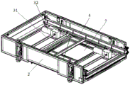
referring to fig. 1 to 5, the present embodiment is a lifting exchange platform 100 for a laser cutting machine, which includes a supporting frame 1, a protective enclosure 2 covering three vertical surfaces of the supporting frame 1, a lifting driving unit 3 disposed on the supporting frame 1, a guide rail unit 4 driven by the lifting driving unit 3 to move up and down, a first working table 5 and a second working table 6 horizontally sliding on the guide rail unit 4 and vertically stacked, a chip collecting box 7 disposed at the bottom of the supporting frame 1 and used for collecting chips, and a positioning mechanism 8 disposed at one end of the guide rail unit 4 and used for fixing the first working table 5 and the second working table 6.
Three vertical surfaces of the support frame 1 are enclosed by the protective enclosure 2, and the first work table 5 and the second work table 6 enter and exit from the fourth opening direction.
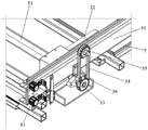
The lifting driving unit 3 is provided with two sets of front and rear parts located on the supporting frames 1, and comprises a rotating shaft 31 rotatably erected between the supporting frames 1, a servo driving part 32 driving the rotating shaft 31 to rotate, driving sprockets 33 fixed at two ends of the rotating shaft 31, driven sprockets 35 realizing transmission with the driving sprockets 33 through a chain 34, and a connecting plate 36 fixed on the chain 34, wherein the connecting plate 36 is fixedly connected with the guide rail unit 4. The two servo driving pieces 32 simultaneously drive the rotating shaft 31 to rotate, then drive the driving chain wheel 33 to rotate, the chain 34 performs a circulating motion, and the connecting plate 36 fixed on the chain 34 performs an up-and-down motion along with the chain 34, thereby performing an up-and-down motion of the guide rail unit 4.
The guide rail unit 4 includes C-shaped support beams 41 disposed in parallel on the left and right sides of the support frame 1, a first support surface 42 and a second support surface 43 disposed on the C-shaped support beams 41 and stacked up and down, a first guide rail 44 disposed on the first support surface 42, and a second guide rail 45 disposed on the second support surface 43. The first table 5 is mounted on two first rails 44, and the second table 6 is mounted on two second rails 45.
The cutting chip collecting box 7 is of a drawer type structure, the bottom of the cutting chip collecting box is provided with the idler wheels, and the end of the cutting chip collecting box 7 is provided with the pull rod, so that an operator can pull the cutting chip collecting box out conveniently.
The first workbench 5 and the second workbench 6 are provided with a traction block 51 near the outlet end of the support frame 1, and the traction block 51 is used for being in butt joint with a traction mechanism to realize position switching between the feeding and discharging area and the cutting area of the first workbench 5 or the second workbench 6. The traction block 51 is provided with vertically distributed clamping grooves 52 with outward openings. The clamping grooves 52 are vertically distributed, so that the freedom degree of the traction shaft is limited in the moving direction of the workbench after the traction shaft is clamped in the clamping grooves 52, and the driving is realized; and the opening of the clamping groove 52 is arranged outwards, so that the action that the traction shaft is clamped into the clamping groove 52 can be finished through the up-and-down movement of the workbench, and the workbench does not need to perform horizontal transplanting movement.
During working, firstly, an operator places a workpiece on the first workbench 5, then drives the guide rail unit 4 to move up and down through the lifting driving unit 3, drives the first workbench 5 to move to the corresponding height of the external traction unit, so that an external traction shaft extends into the clamping groove 52 in the traction block 51, and the external traction unit pulls out the first workbench 5 to enter a cutting area for processing; in the machining process, an operator places a workpiece to be machined on the second workbench 6; after the machining is finished, the external traction unit pushes the first workbench 5 back to the guide rail unit 4 and is positioned by the positioning mechanism 8; then lifting drive unit 3 drive guide rail unit 4 up-and-down motion takes second workstation 6 to move to outside traction unit and corresponds the height, make outside traction shaft stretch into in the traction block 51 on second workstation 6, and pull out second workstation 6 and process to cutting area, at this moment, operating personnel takes off the work piece of processing on with first workstation 5 and accomplishes the unloading, the unloading in-process, the smear metal on the workstation can fall into in the smear metal collection box 7 of below through the table surface of fretwork.
The lifting exchange platform 100 for the laser cutting machine of the embodiment realizes automatic switching between the upper and lower laminated working platforms in a cutting area and a loading and unloading position, realizes up-and-down movement of a guide rail unit through a chain wheel and a chain, simultaneously drives the working platform to realize lifting movement, is driven by the chain wheel and the chain and driven by a servo motor, effectively avoids pause and frustration of oil cylinder or air cylinder driving, and greatly improves the lifting stability of the working platform; the guide rail unit is provided with the positioning mechanism, so that the working table top can be kept stable and does not slide when being arranged on the guide rail unit, and the machining precision of the workpiece is guaranteed; the cuttings collection box arranged below the workbench effectively prevents cuttings from falling into the guide rail to influence the sliding of the platform.
What has been described above are only some embodiments of the invention. For those skilled in the art, without departing from the inventive concept, several modifications and improvements can be made, which are within the scope of the invention.
Claims (8)
1. The utility model provides a laser cutting machine is with over-and-under type exchange platform which characterized in that: which comprises a supporting frame, a lifting driving unit arranged on the supporting frame, a guide rail unit driven by the lifting driving unit to move up and down, a first workbench and a second workbench which horizontally slide on the guide rail unit and are distributed in an up-and-down laminated manner, a cutting scrap collecting box arranged at the bottom of the supporting frame and used for collecting cutting scraps, and a positioning mechanism arranged at one end of the guide rail unit and used for fixing the first workbench and the second workbench, the lift drive unit is provided with two sets of being located support frame's front and back part just includes rotatable erects pivot, drive between the support frame the rotatory servo driving piece of pivot, fix the drive sprocket at pivot both ends, through the chain with drive sprocket realizes driven sprocket, fixes connecting plate on the chain, the connecting plate with guide rail unit fixed connection.
2. The lift-type exchange platform for a laser cutting machine of claim 1, wherein: still including the parcel live the fender of the three vertical face of braced frame encloses the fender, braced frame's three vertical face quilt the protection encloses the fender and encloses, first workstation with the second workstation passes in and out from fourth opening direction.
3. The lift-type exchange platform for a laser cutting machine of claim 1, wherein: the guide rail unit comprises C-shaped supporting beams arranged on the left side and the right side of the supporting frame in parallel, a first supporting surface and a second supporting surface which are arranged on the C-shaped supporting beams and distributed in an up-and-down laminated mode, a first guide rail arranged on the first supporting surface, and a second guide rail arranged on the second supporting surface.
4. The lift-type exchange platform for a laser cutting machine of claim 3, wherein: the first working table is arranged on the two first guide rails, and the second working table is arranged on the two second guide rails.
5. The lift-type exchange platform for a laser cutting machine of claim 1, wherein: the cutting chip collecting box is of a drawer type structure, the bottom of the cutting chip collecting box is provided with a roller, and the end part of the cutting chip collecting box is provided with a pull rod.
6. The lift-type exchange platform for a laser cutting machine of claim 1, wherein: and the first workbench and the second workbench are close to the outlet end of the support frame and are provided with traction blocks.
7. The lift-type exchange platform for a laser cutting machine of claim 6, wherein: the traction block is provided with clamping grooves which are vertically distributed and have outward openings.
8. The lift-type exchange platform for a laser cutting machine of claim 3, wherein: first workstation with the one end both sides of second workstation still are provided with the location fixture block, positioning mechanism is provided with four and divide into two sets of being located two on the guide rail unit, and including fixing location cylinder on the C type supporting beam, receive location cylinder drive carries out horizontal migration and card income spacing post in the location fixture block.
Priority Applications (1)
| Application Number | Priority Date | Filing Date | Title |
|---|---|---|---|
| CN201921429282.1U CN210937726U (en) | 2019-08-30 | 2019-08-30 | Over-and-under type exchange platform for laser cutting machine |
Applications Claiming Priority (1)
| Application Number | Priority Date | Filing Date | Title |
|---|---|---|---|
| CN201921429282.1U CN210937726U (en) | 2019-08-30 | 2019-08-30 | Over-and-under type exchange platform for laser cutting machine |
Publications (1)
| Publication Number | Publication Date |
|---|---|
| CN210937726U true CN210937726U (en) | 2020-07-07 |
Family
ID=71369918
Family Applications (1)
| Application Number | Title | Priority Date | Filing Date |
|---|---|---|---|
| CN201921429282.1U Active CN210937726U (en) | 2019-08-30 | 2019-08-30 | Over-and-under type exchange platform for laser cutting machine |
Country Status (1)
| Country | Link |
|---|---|
| CN (1) | CN210937726U (en) |
-
2019
- 2019-08-30 CN CN201921429282.1U patent/CN210937726U/en active Active
Similar Documents
| Publication | Publication Date | Title |
|---|---|---|
| CN113478235A (en) | Efficient processing production line and processing method for door and window profiles | |
| CN204771172U (en) | Double -deck exchange formula workstation of laser cutting machine | |
| CN201154421Y (en) | Laser cutting machine | |
| CN210937695U (en) | Over-and-under type exchange platform laser cutting machine of rapid cooling | |
| LU501497B1 (en) | Double-station movable worktable for laser cutting machine | |
| US20050031426A1 (en) | Machine tool | |
| CN210937726U (en) | Over-and-under type exchange platform for laser cutting machine | |
| CN216028839U (en) | Guide rail module processing laser cutting machine | |
| CN218904014U (en) | Fiber laser cutting machine capable of pushing blanking | |
| CN115922105A (en) | Double-workbench type three-dimensional laser cutting machine | |
| CN110653880A (en) | Automatic processing machine for woodworking saw cutting with suspended cutter | |
| CN216607462U (en) | Vertical saw cutting machining device for door and window profile | |
| CN115091037A (en) | Laser edge cleaning cutting machine with automatic material receiving function | |
| CN212977173U (en) | Laser cutting machine | |
| CN210999128U (en) | Double-end horizontal saw device | |
| CN210588394U (en) | Automatic milling processing equipment | |
| CN209969884U (en) | Integrative cutting machine of two longmen board pipes | |
| CN112404546A (en) | Iron plate cutting production line for angle steel tower | |
| CN220196647U (en) | Engraving cutting machine convenient for feeding and discharging | |
| CN111805098A (en) | Exchange workbench type laser cutting machine | |
| CN219986558U (en) | Laser cutting processing table | |
| CN220591956U (en) | Gantry linear motor laser cutting equipment | |
| CN218253404U (en) | Laser edge cleaning cutting machine with automatic material receiving function | |
| CN216097034U (en) | A unloader for sheet metal component processing | |
| CN214868999U (en) | Subway junction box panel machining center |
Legal Events
| Date | Code | Title | Description |
|---|---|---|---|
| GR01 | Patent grant | ||
| GR01 | Patent grant |