CN210907039U - Dust collector for double electric layer capacitor - Google Patents
Dust collector for double electric layer capacitor Download PDFInfo
- Publication number
- CN210907039U CN210907039U CN201921923902.7U CN201921923902U CN210907039U CN 210907039 U CN210907039 U CN 210907039U CN 201921923902 U CN201921923902 U CN 201921923902U CN 210907039 U CN210907039 U CN 210907039U
- Authority
- CN
- China
- Prior art keywords
- fixedly connected
- dust
- cabinet
- servo motor
- layer capacitor
- Prior art date
- Legal status (The legal status is an assumption and is not a legal conclusion. Google has not performed a legal analysis and makes no representation as to the accuracy of the status listed.)
- Active
Links
Images


Abstract
The utility model discloses a dust collector for electric double layer capacitor, including the bottom plate, the one end fixedly connected with collection dirt cabinet at bottom plate top, the one end fixed mounting at collection dirt cabinet top has control panel, and control panel's one end fixedly connected with guard box is kept away from at collection dirt cabinet's top, and the bottom fixed mounting of guard box inner wall has the suction fan, and two fixed plates of one end fixedly connected with of collection dirt cabinet are kept away from at the top of bottom plate, the utility model discloses the beneficial effect who reaches is: the utility model discloses compact structure, easy operation is convenient, and the practicality is strong, controls drive mechanism through setting up, drives the brush of certain quantity and removes to clean the dust on electric double layer capacitor surface, adsorb the dust of the clean production of brush through setting up the suction fan simultaneously, thereby prevent that the dust from flying in disorder, in addition through setting up the screw drive, make equipment can clean the position of eminence, thereby very big increase clear scope, and reduced staff's intensity of labour.
Description
Technical Field
The utility model relates to a dust collector, in particular to dust collector for electric double layer capacitor belongs to dust collector technical field.
Background
In the existing life, a direct current power supply is taken as a power supply source, plays an important role in power supply systems of substations, power plants, large and medium-sized factory and mining enterprises and the like, is mainly used for supplying power to transmission mechanisms of switching-on and switching-off operation, control, protection, communication equipment, automatic device operation machinery and adjusting machinery, and can also be taken as an independent emergency lighting power supply, so the performance and reliability of the direct current power supply directly influence the normal and safe operation of the whole power supply system, at present, most direct currents adopt storage batteries as energy storage elements, but charging devices of storage battery packs are complex, the charger is required to be charged according to charging curves of battery characteristics under the conditions of voltage limiting and current limiting, the ripple coefficient of charging voltage is overlarge, the service life of the storage batteries is damaged, therefore, the charger needs to be provided with a filter device, the storage batteries have high requirements on, consequently can adopt the mixed energy storage DC power supply scheme of electric double layer capacitor and battery in the current transformer substation, but electric double layer capacitor can produce a lot of dusts on long-term in-process surface of using, if untimely handling, can influence the use, but at present to the cleanness of electric double layer capacitor surface dust, remove dust through artifical air-blower, perhaps remove dust with the brush, can't clean the dust of eminence, and cause the indiscriminate condition about flying of dust to take place easily, simultaneously cleaning efficiency is low, very big increase the amount of labour.
SUMMERY OF THE UTILITY MODEL
The to-be-solved technical problem of the utility model is to overcome prior art's defect, provide a dust collector for electric double layer capacitor.
In order to solve the technical problem, the utility model provides a following technical scheme:
the utility model relates to a dust collector for double electric layer capacitor, which comprises a base plate, one end at the top of the base plate is fixedly connected with a dust collecting cabinet, one end at the top of the dust collecting cabinet is fixedly provided with a control panel, one end at the top of the dust collecting cabinet far away from the control panel is fixedly connected with a protection box, the bottom of the inner wall of the protection box is fixedly provided with a suction fan, one end at the top of the base plate far away from the dust collecting cabinet is fixedly connected with two fixed plates, two fixed plates are fixedly connected with a transverse plate between the tops of the fixed plates, one end at the top of the transverse plate is fixedly provided with a first servo motor, a slide bar is fixedly connected between one end at the bottom of the transverse plate and the top of the base plate, a screw rod is rotatably connected between one end at the bottom of the transverse plate far, the outer side of the screw rod is in threaded connection with a transmission case, one end of the transmission case, far away from the screw rod, is in sliding connection with the slide rod, two sides of the transmission case are in sliding connection with corresponding fixed plates, one end of the bottom of the transmission case, far away from the dust collection cabinet, is fixedly connected with a connecting plate, one side of the connecting plate, far away from the dust collection cabinet, is fixedly connected with a dust suction nozzle, one side of the transmission case, far away from the dust collection cabinet, is provided with a chute, one end of the bottom of the inner wall of the transmission case is fixedly provided with a second servo motor, an output shaft of the second servo motor is fixedly connected with a rotating wheel, the outer side of the rotating wheel is provided with a limiting groove, one side of the bottom of the inner wall of the transmission case, which is positioned at the bottom of the second servo motor, is fixedly connected with a fixed, two fixedly connected with carriage release lever between the top of slider, one side that the carriage release lever is close to the rotation wheel is dug and is had the rotation groove, the inside rotation in rotation groove is connected with the gyro wheel, the one end that the carriage release lever was kept away from to the gyro wheel extend to the inside of spacing groove and with spacing groove sliding connection, one side equidistance fixedly connected with a plurality of connecting rod of carriage release lever, the one end that the carriage release lever was kept away from to the connecting rod all runs through the outside that the spout extended to the transmission case, the connecting rod all with spout sliding connection, the one end of connecting rod just is located the equal fixedly connected with brush in the outside of transmission case.
As an optimized scheme of the utility model, the equal fixed mounting in four corners of bottom plate bottom has the auto-lock wheel.
As an optimized scheme of the utility model, one side of collection dirt cabinet is rotated and is connected with the cabinet door, cabinet door outside one end is excavated fluted handle.
As a preferred scheme of the utility model, the output of suction fan extends to the outside of guard box and the first connecting pipe of fixedly connected with, the one end that the suction fan was kept away from to first connecting pipe extends to the inside of album dirt cabinet, the input of suction fan extends to the outside of guard box and fixedly connected with second connecting pipe, the one end of keeping away from the suction fan of second connecting pipe runs through the connecting plate and communicates with each other with the inside of dust absorption mouth, just one side equidistance of guard box is dug and is had a plurality of louvre.
As an optimal solution of the present invention, the rotating wheel is eccentrically connected to the second servo motor.
As a preferred scheme of the utility model, one side fixedly connected with return spring of second servo motor is kept away from to the inner wall of dead lever, return spring keeps away from the one end of dead lever inner wall and the slider fixed connection who corresponds.
As an optimized scheme of the utility model, equal and the control panel electric connection of suction fan, first servo motor, second servo motor.
The utility model discloses the beneficial effect who reaches is: the utility model discloses compact structure, easy operation is convenient, and the practicality is strong, controls drive mechanism through setting up, drives the brush of certain quantity and removes to clean the dust on electric double layer capacitor surface, adsorb the dust of the clean production of brush through setting up the suction fan simultaneously, thereby prevent that the dust from flying in disorder, in addition through setting up the screw drive, make equipment can clean the position of eminence, thereby very big increase clear scope, and reduced staff's intensity of labour.
Drawings
The accompanying drawings are included to provide a further understanding of the invention, and are incorporated in and constitute a part of this specification, illustrate embodiments of the invention, and together with the description serve to explain the invention and not to limit the invention. In the drawings:
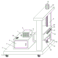
FIG. 1 is a schematic view of the overall structure of the present invention;
FIG. 2 is a front view of the present invention;
fig. 3 is a side view of the present invention;
fig. 4 is a schematic view of a part of the structure of the present invention.
In the figure: 1. a base plate; 2. a self-locking wheel; 3. a dust collecting cabinet; 4. a cabinet door; 5. a protection box; 6. a suction fan; 7. a first connecting pipe; 8. a second connecting pipe; 9. a fixing plate; 10. a transverse plate; 11. a first servo motor; 12. a slide bar; 13. a screw rod; 14. a transmission case; 15. a connecting plate; 16. a dust suction nozzle; 17. a second servo motor; 18. a rotating wheel; 19. a limiting groove; 20. fixing the rod; 21. a slider; 22. a return spring; 23. a travel bar; 24. a rotating groove; 25. a roller; 26. a connecting rod; 27. a brush; 28. a control panel; 29. a chute.
Detailed Description
The preferred embodiments of the present invention will be described in conjunction with the accompanying drawings, and it will be understood that they are presented herein only to illustrate and explain the present invention, and not to limit the present invention.
Examples
As shown in fig. 1-4, the utility model provides a dust removing device for a double electric layer capacitor, which comprises a bottom plate 1, wherein a dust collecting cabinet 3 is fixedly connected with one end of the top of the bottom plate 1, so that dust can be better collected; a control panel 28 is fixedly installed at one end of the top of the dust collection cabinet 3, a protection box 5 is fixedly connected at one end of the top of the dust collection cabinet 3 far away from the control panel 28, a suction fan 6 is fixedly installed at the bottom of the inner wall of the protection box 5, and the suction fan 6 is protected better through the protection box 5; the end, far away from the dust collecting cabinet 3, of the top of the bottom plate 1 is fixedly connected with two fixing plates 9, a transverse plate 10 is fixedly connected between the tops of the two fixing plates 9, one end of the top of the transverse plate 10 is fixedly provided with a first servo motor 11, a slide rod 12 is fixedly connected between one end of the bottom of the transverse plate 10 and the top of the bottom plate 1, a lead screw 13 is rotatably connected between one end, far away from the slide rod 12, of the bottom of the transverse plate 10 and the top of the bottom plate 1, an output shaft of the first servo motor 11 extends to the bottom of the transverse plate 10 and is fixedly connected with the lead screw 13 through a coupler, the outer side of the lead screw 13 is in threaded connection with a transmission case 14, one end, far away from the lead screw 13, of the transmission case 14 is in sliding connection with; one end of the bottom of the transmission box 14, which is far away from the dust collecting cabinet 3, is fixedly connected with a connecting plate 15, and one side of the connecting plate 15, which is far away from the dust collecting cabinet 3, is fixedly connected with a dust suction nozzle 16, so that dust can be better adsorbed; a sliding groove 29 is formed in one side, away from the dust collection cabinet 3, of the transmission box 14, a second servo motor 17 is fixedly mounted at one end of the bottom of the inner wall of the transmission box 14, an output shaft of the second servo motor 17 is fixedly connected with a rotating wheel 18, a limiting groove 19 is formed in the outer side of the rotating wheel 18, a fixing rod 20 of a U-shaped structure is fixedly connected to one side, located on the second servo motor 17, of the bottom of the inner wall of the transmission box 14, two sliding blocks 21 are slidably connected to the outer side of the fixing rod 20, and the bottoms of the sliding blocks 21 are slidably connected with the bottom of the inner wall of the transmission box 14, so that the sliding blocks 21; fixedly connected with carriage release lever 23 between the top of two sliders 21, one side that carriage release lever 23 is close to and rotates wheel 18 is dug and is had rotation groove 24, the internal rotation that rotates groove 24 is connected with gyro wheel 25, the one end that carriage release lever 23 was kept away from to gyro wheel 25 extends to the inside of spacing groove 19 and with spacing groove 19 sliding connection, one side equidistance fixedly connected with a plurality of connecting rod 26 of carriage release lever 23, the one end that moving lever 23 was kept away from to connecting rod 26 all runs through the outside that spout 29 extended to transmission case 14, connecting rod 26 all with spout 29 sliding connection, the one end of connecting rod 26 just is located the equal fixedly connected with brush 27 in the outside of transmission case 14, be convenient for better clean the dust on electric double layer capacitor surface.
Further, the four corners of the bottom plate 1 are fixedly provided with self-locking wheels 2, so that the equipment can be moved and fixed better.
Further, one side of the dust collecting cabinet 3 is rotatably connected with a cabinet door 4, one end of the outer side of the cabinet door 4 is provided with a groove handle, and the cabinet door 4 can be conveniently and better opened through the groove handle, so that the dust in the dust collecting cabinet 3 can be better treated.
Further, the output of suction fan 6 extends to the outside of guard box 5 and the first connecting pipe 7 of fixedly connected with, the one end that first connecting pipe 7 kept away from suction fan 6 extends to the inside of collection dirt cabinet 3, the input of suction fan 6 extends to the outside of guard box 5 and fixedly connected with second connecting pipe 8, the one end of keeping away from suction fan 6 of second connecting pipe 8 runs through connecting plate 15 and communicates with each other with the inside of dust absorption mouth 16, and one side equidistance of guard box 5 is dug and is had a plurality of louvre, be convenient for better dispel the heat to suction fan 6 through the louvre, simultaneously through first connecting pipe 7, the cooperation between second connecting pipe 8 and the suction fan 6 can be better collect the dust, prevent that the dust from flying in a disorderly.
Further, the rotating wheel 18 is eccentrically connected with the second servo motor 17, and the moving rod 23 can be pushed to move left and right through the eccentrically connected rotating wheel 18.
Further, one side of the inner wall of the fixing rod 20, which is far away from the second servo motor 17, is fixedly connected with a return spring 22, one end of the return spring 22, which is far away from the inner wall of the fixing rod 20, is fixedly connected with the corresponding sliding block 21, and under the action of the return spring 22, the roller 25 can be always located inside the limiting groove 19.
Furthermore, the suction fan 6, the first servo motor 11 and the second servo motor 17 are electrically connected with the control panel 28, so that the equipment can be better controlled.
Specifically, the device is moved to a designated position through the self-locking wheel 2, so that the brush 27 can contact the surface of the electric double layer capacitor, then the device is powered on, the second servo motor 17 is controlled to work through the control panel 28, the rotating wheel 18 is driven to rotate, the moving rod 23 and the sliding block 21 are driven to slide back and forth outside the fixed rod 20 through the cooperation between the roller 25 and the return spring 22, the connecting rod 26 and the brush 27 can be driven to slide inside the sliding groove 29, so that the dust on the surface of the electric double layer capacitor is cleaned, meanwhile, the suction fan 6 is controlled to work through the control panel 28, the dust swept by the brush 27 is sucked into the dust collection cabinet 3 through the dust suction nozzle 16 for storage, the dust is prevented from flying in a mess, then the rotor inside the first servo motor 11 is controlled to rotate forward and backward through the control panel 28, the lead screw 13 is driven to rotate, so that the transmission case 14 is driven to, make brush 27 can clean the dust of different height positions to increased clear scope, after clean the completion, open cabinet door 4 through the recess handle, handle the dust of collection dirt cabinet 3 inside can.
Finally, it should be noted that: although the present invention has been described in detail with reference to the foregoing embodiments, it will be apparent to those skilled in the art that modifications may be made to the embodiments described in the foregoing embodiments, or equivalents may be substituted for elements thereof. Any modification, equivalent replacement, or improvement made within the spirit and principle of the present invention should be included in the protection scope of the present invention.
Claims (7)
1. The utility model provides a dust collector for double electric layer capacitor, includes bottom plate (1), its characterized in that, the one end fixedly connected with collection dirt cabinet (3) at bottom plate (1) top, the one end fixed mounting at collection dirt cabinet (3) top has control panel (28), the one end fixedly connected with guard box (5) of control panel (28) are kept away from at the top of collection dirt cabinet (3), the bottom fixed mounting of guard box (5) inner wall has suction fan (6), the one end fixedly connected with two fixed plates (9) of collection dirt cabinet (3) are kept away from at the top of bottom plate (1), two fixedly connected with diaphragm (10) between the top of fixed plate (9), the one end fixed mounting at diaphragm (10) top has first servo motor (11), fixedly connected with slide bar (12) between the one end of diaphragm (10) bottom and the top of bottom plate (1), the bottom of the transverse plate (10) is far away from a screw rod (13) between one end of the sliding rod (12) and the top of the bottom plate (1), an output shaft of the first servo motor (11) extends to the bottom of the transverse plate (10) and is fixedly connected with the screw rod (13) through a coupler, the outer side of the screw rod (13) is in threaded connection with a transmission box (14), one end of the transmission box (14), far away from the screw rod (13), is in sliding connection with the sliding rod (12), the two sides of the transmission box (14) are in sliding connection with corresponding fixing plates (9), one end of the bottom of the transmission box (14), far away from the dust collection cabinet (3), is fixedly connected with a connecting plate (15), one side of the connecting plate (15), far away from the dust collection cabinet (3), one side of the transmission box (14), far away from the dust collection cabinet (3), is provided with a sliding groove (29), one end fixed mounting of transmission case (14) inner wall bottom has second servo motor (17), the output shaft fixedly connected with of second servo motor (17) rotates wheel (18), the outside of rotating wheel (18) is excavated spacing groove (19), the bottom of transmission case (14) inner wall just is located dead lever (20) of one side fixedly connected with "U" style of calligraphy structure of second servo motor (17), the outside sliding connection of dead lever (20) has two sliders (21), the bottom of slider (21) all with the bottom sliding connection of transmission case (14) inner wall, two fixedly connected with carriage release lever (23) between the top of slider (21), carriage release lever (23) are close to one side of rotating wheel (18) and are excavated and have rotation groove (24), the inside rotation of rotation groove (24) is connected with gyro wheel (25), gyro wheel (25) keep away from the one end of carriage release lever (23) extend to the inside of spacing groove (19) and with spacing groove (19), the spacing Groove (19) sliding connection, one side equidistance fixedly connected with a plurality of connecting rod (26) of carriage release lever (23), the one end that carriage release lever (23) was kept away from in connecting rod (26) all runs through the outside that spout (29) extended to transmission case (14), connecting rod (26) all with spout (29) sliding connection, the one end of connecting rod (26) just is located equal fixedly connected with brush (27) in the outside of transmission case (14).
2. The dust removing device for the electric double layer capacitor as claimed in claim 1, wherein the self-locking wheels (2) are fixedly mounted at four corners of the bottom plate (1).
3. The dust removing device for the electric double layer capacitor as recited in claim 1, wherein a cabinet door (4) is rotatably connected to one side of the dust collecting cabinet (3), and a handle with a groove is formed at one end of the outer side of the cabinet door (4).
4. The dust removing device for the electric double layer capacitor as recited in claim 1, wherein the output end of the suction fan (6) extends to the outer side of the protection box (5) and is fixedly connected with a first connecting pipe (7), one end of the first connecting pipe (7) far away from the suction fan (6) extends to the inside of the dust collection cabinet (3), the input end of the suction fan (6) extends to the outer side of the protection box (5) and is fixedly connected with a second connecting pipe (8), one end of the second connecting pipe (8) far away from the suction fan (6) penetrates through the connecting plate (15) and is communicated with the inside of the dust collection nozzle (16), and a plurality of heat dissipation holes are drilled in one side of the protection box (5) at equal intervals.
5. The precipitator for electric double layer capacitors according to claim 1, wherein the rotating wheel (18) is eccentrically connected to the second servomotor (17).
6. The dust removing device for the electric double layer capacitor as recited in claim 1, wherein a return spring (22) is fixedly connected to a side of the inner wall of the fixing rod (20) away from the second servo motor (17), and one end of the return spring (22) away from the inner wall of the fixing rod (20) is fixedly connected to the corresponding slider (21).
7. The dust removing device for the electric double layer capacitor as recited in claim 1, wherein the suction fan (6), the first servo motor (11) and the second servo motor (17) are electrically connected with the control panel (28).
Priority Applications (1)
| Application Number | Priority Date | Filing Date | Title |
|---|---|---|---|
| CN201921923902.7U CN210907039U (en) | 2019-11-09 | 2019-11-09 | Dust collector for double electric layer capacitor |
Applications Claiming Priority (1)
| Application Number | Priority Date | Filing Date | Title |
|---|---|---|---|
| CN201921923902.7U CN210907039U (en) | 2019-11-09 | 2019-11-09 | Dust collector for double electric layer capacitor |
Publications (1)
| Publication Number | Publication Date |
|---|---|
| CN210907039U true CN210907039U (en) | 2020-07-03 |
Family
ID=71364673
Family Applications (1)
| Application Number | Title | Priority Date | Filing Date |
|---|---|---|---|
| CN201921923902.7U Active CN210907039U (en) | 2019-11-09 | 2019-11-09 | Dust collector for double electric layer capacitor |
Country Status (1)
| Country | Link |
|---|---|
| CN (1) | CN210907039U (en) |
Cited By (2)
| Publication number | Priority date | Publication date | Assignee | Title |
|---|---|---|---|---|
| CN112957856A (en) * | 2021-03-04 | 2021-06-15 | 惠东嘉华材料有限公司 | Environment-friendly dust removal device for mining equipment exploitation and dust removal method thereof |
| CN114308746A (en) * | 2021-10-27 | 2022-04-12 | 中国科学院光电技术研究所 | Cleaning device for optical system of mid-infrared spectrum analyzer |
-
2019
- 2019-11-09 CN CN201921923902.7U patent/CN210907039U/en active Active
Cited By (2)
| Publication number | Priority date | Publication date | Assignee | Title |
|---|---|---|---|---|
| CN112957856A (en) * | 2021-03-04 | 2021-06-15 | 惠东嘉华材料有限公司 | Environment-friendly dust removal device for mining equipment exploitation and dust removal method thereof |
| CN114308746A (en) * | 2021-10-27 | 2022-04-12 | 中国科学院光电技术研究所 | Cleaning device for optical system of mid-infrared spectrum analyzer |
Similar Documents
| Publication | Publication Date | Title |
|---|---|---|
| CN210907039U (en) | Dust collector for double electric layer capacitor | |
| CN204760782U (en) | Automatic dust removal electric power cabinet | |
| CN218606388U (en) | Floor sweeping robot | |
| CN211191113U (en) | Dust removal device for transformer substation | |
| CN111229662A (en) | Ash removal device for transformer bearing seat of transformer substation | |
| CN209429031U (en) | A kind of railroad track sand-removal device | |
| CN116505862A (en) | Intelligent dust removal device for distributed photovoltaic power generation panel | |
| CN215918473U (en) | Cleaning device for high-voltage power distribution cabinet | |
| CN215582197U (en) | High-efficient heat dissipation communication management machine | |
| CN216121246U (en) | Dedusting cleaning type intelligent switch cabinet | |
| CN106345209B (en) | A kind of dust pelletizing system of optimization blower fan structure | |
| CN210640595U (en) | Dustproof and rainproof ventilation device for transformer substation | |
| CN205236490U (en) | Solar cell panel intelligence dust pelletizing system | |
| CN213358456U (en) | Municipal administration is with removing dust and falling haze device | |
| CN210411611U (en) | Power control box for photovoltaic power generation | |
| CN220628550U (en) | Switch board with cabinet mouth clearance function | |
| CN214976333U (en) | Wisdom heat supply network is with trading power station dust collector | |
| CN215071038U (en) | Novel multifunctional capacitance compensation cabinet | |
| CN220629284U (en) | Novel photovoltaic power generation device | |
| CN211938004U (en) | Ash removal device for transformer bearing seat of transformer substation | |
| CN212909429U (en) | Photovoltaic board with automatic deashing function | |
| CN220738833U (en) | Electric dust collector | |
| CN220324973U (en) | Electrical equipment protection device | |
| CN210395062U (en) | Highway construction curing means | |
| CN218074811U (en) | Robot integrating cleaning and garbage adsorption |
Legal Events
| Date | Code | Title | Description |
|---|---|---|---|
| GR01 | Patent grant | ||
| GR01 | Patent grant |