CN210875757U - Dustless environmental protection analysis system sand powder process device of slay - Google Patents
Dustless environmental protection analysis system sand powder process device of slay Download PDFInfo
- Publication number
- CN210875757U CN210875757U CN201921085159.2U CN201921085159U CN210875757U CN 210875757 U CN210875757 U CN 210875757U CN 201921085159 U CN201921085159 U CN 201921085159U CN 210875757 U CN210875757 U CN 210875757U
- Authority
- CN
- China
- Prior art keywords
- feeding
- powder
- sieve
- spiral conveying
- motor
- Prior art date
- Legal status (The legal status is an assumption and is not a legal conclusion. Google has not performed a legal analysis and makes no representation as to the accuracy of the status listed.)
- Active
Links
Images


Landscapes
- Disintegrating Or Milling (AREA)
Abstract
The utility model discloses a dust-free and environment-friendly slag analysis sand making and powder making device, which comprises a feeding device, a lifter, a crusher, a translational powder feeding separator, a spiral conveying pipe, a feed back belt and a dust removal recovery device; the feeding device is connected with a first lifting machine through a spiral conveying pipe, the first lifting machine is in contact connection with a first layer of sieve plate of a primary grinding machine, the primary grinding machine is in contact connection with an uppermost layer of sieve plate of a secondary grinding machine through a second lifting machine, the secondary grinding machine is in contact connection with a first-stage feeding plate of a translational powder feeding sorting machine through a third lifting machine, and a return material receiving port of the translational powder feeding sorting machine is in contact connection with an uppermost-stage sieve plate of a secondary grinding machine through a return material belt; through the processing of full automatic feed device, hoisting device, hierarchical crushing and repayment crushing flow to industrial ore waste residue, can realize that high efficiency, high-quality slay are smashed, reach the processing of handling into the grit that can directly use with the slay.
Description
Technical Field
The utility model relates to an industrial waste residue and ore rubble processing equipment technical field specifically are a dustless environmental protection analysis system sand powder process device of slay.
Background
The treatment of industrial macadam all belongs to the processing technique of high cost low income at home and abroad, and the processing of the macadam into the relevant equipment that specific specification can directly be used production and running cost are all very high, and in the in-process of processing the macadam, can produce a large amount of dust moreover, not only can cause serious health harm to the operator, also can cause more serious pollution to the environment.
Related industrial slag and blast furnace smelting slag are generally subjected to rough machining and crushing through jaw crushing and cone crushing and then are subjected to secondary utilization, however, the size and specification of the treated slag cannot meet the use requirements of different projects and the project quality can be influenced; the hardness of the slag cannot be screened, so that the application range of the processed slag is influenced; the quality of the slag can not be refined and screened, the recycling of the processed slag is seriously influenced, and the green production of factory processing is not facilitated.
In the smelting industry, a large amount of burned industrial combustion waste residues are generated in the industrial preparation process, and through primary crushing, a large amount of waste residues can be directly abandoned, so that the waste materials are not easy to decompose and can cause very serious influence on the environment; most of industrial waste residues are treated as raw materials for paving a roadbed through primary crushing at the present stage or are subjected to special decomposition to be used as raw materials for processing novel building materials, but the application effect is poor, the raw materials for the roadbed are dangerous because slag edges and corners are too sharp, the processing process is too complicated, the cost is increased, and the practicability is low; therefore, the process is widely used by those skilled in the related art by classifying and crushing the primary crushed slag into fine sand, and at this stage, a large-scale fully automatic processing apparatus is used for the primary slag processing related equipment, and a large amount of dust is generated during the slag processing, which causes physical harm to operators and serious environmental pollution.
SUMMERY OF THE UTILITY MODEL
The utility model aims to solve the technical problem that a full-automatic dustless environmental protection system sand equipment of slay of hierarchical breakage, dustless processing is provided.
The technical scheme of the utility model is that: a dust-free environment-friendly slag analysis sand making and pulverizing device comprises a feeding device, a supporting column, a feeding platform, a hopper, a feeding spiral conveying support, a buffer spring, a first elevator, a second elevator, a third elevator, an elevator shell, a feeding port, a discharging port, a lifting driving wheel, a lifting belt, a material containing hopper, a primary crusher, a secondary crusher, a first-layer sieve plate, a second-layer sieve plate, a third-layer sieve plate, a powder conveying plate, a crushing driving wheel, a first-layer crushing roller, a second-layer crushing roller, a crushing motor, a translational powder conveying separator, a first-layer feeding sieve plate, a second-layer feeding sieve plate, a third-layer feeding sieve plate, a separating powder conveying plate, a feeding driving wheel, a feeding motor, a first-layer receiving sieve, a second-layer receiving sieve, a receiving powder conveying plate, a receiving driving wheel, a receiving motor, a return material receiving port, a, The device comprises a powder inlet, a powder outlet, an anti-blocking cover plate, a feed back belt, a dust removal recovery device, a dust removal recovery fan, a discharge pipe, a first screw conveyor, a hopper, a discharger, a discharge box, a separator, a suction fan, a suction motor, a first fan, a cyclone dust collector, a bag-type dust collector, a second fan, a discharge pipe, a material lifting machine, a first air-lock valve, a powder bin, a rotary control valve, a valve motor, a second screw conveyor, a second air-lock valve, a third air-lock valve, a mill, a cooling spray device and a balance pipe; four corners below the feeding device are provided with four support columns which support the whole feeding device, the feeding platform is of a slightly-inclined plate surface structure which can enable raw materials fed into the feeding device to slowly enter a hopper, a feeding hole is formed in the rear position of the feeding platform, the hopper is connected below the feeding hole and is in a square funnel shape so that the raw materials can be conveniently collected and fall down, feeding spiral conveying is arranged below the hopper, a feeding spiral conveying support is arranged below the feeding spiral conveying support, four corners of the feeding spiral conveying support are respectively provided with a buffer spring which can buffer and reduce noise while ensuring the raw materials to stably enter, the feeding device is conveyed to a lifting machine through spiral conveying and conveys the raw materials to a primary crushing device through the lifting machine, and the outer part of the lifting machine is of a structure with a semicircular upper end and a rectangular lower part, lifting machine casing below be provided with the feed inlet of infundibulate, lifting machine casing top be provided with the discharge gate of funnel shape, lifting machine casing in the upper and lower position respectively be provided with a promotion drive wheel with the specification, the promotion drive wheel drive by driving motor, the lifting machine drive wheel pass through the elevator belt and connect, holding hopper fall trapezoidal structure for cavity and be a plurality of evenly be fixed in on the elevator belt, the outside rubbing crusher shell that is equipped with of primary crusher, primary crusher in from top to bottom evenly be provided with one deck sieve, two layers of sieve, three-layer sieve and send the powder board, one deck, two layers, three-layer sieve are the sieve mesh design that reduces step by step and can guarantee that hierarchical kibbling slay carries out crushing treatment step by step, send the powder board to push back the low level for sclausura eye platelike structure, and one deck, two layers of, The three layers of sieve plates and the powder feeding plate are connected to realize common movement and are in contact connection with a crushing driving wheel arranged outside a shell of the crusher through a vibration shaft, the lengths of the first layer of sieve plate, the second layer of sieve plate and the third layer of sieve plate are gradually increased, a first-level crushing roller is arranged below the tail end of the first layer of sieve plate, a second-level crushing roller is arranged below the tail end of the second layer of sieve plate, the crushing rollers are in double-roller design and are connected with a shaft in the crushing driving wheel through a connecting shaft and a belt, the crushing driving wheel is connected with a crushing motor through the belt, a raw material discharge port and a primary powder feeding discharge port are designed at the tail end of the primary crusher corresponding to the third layer of sieve plate and the powder feeding plate, the raw material discharge port is connected with a feed port of a lifting machine II with the same structure, the primary powder feeding discharge port is connected with a, the sizes of the holes of the sieve plates corresponding to the first layer of sieve plate, the second layer of sieve plate and the third layer of sieve plate and the gaps of the crushing rollers are different and are designed to gradually decrease the holes and gradually decrease the gaps of the crushing rollers, the translational powder feeding separator is designed in parallel with a plurality of sieve plates, the first-stage feeding sieve plate, the second-stage feeding sieve plate, the third-stage feeding sieve plate and the separating powder feeding plate are arranged in the front half part of the translational powder feeding separator from top to bottom and are connected with a feeding driving wheel arranged outside the shell of the translational powder feeding separator in a contact way through a vibration shaft, the feeding driving wheel is connected with a feeding motor through a belt, the first-stage receiving sieve, the second-stage receiving sieve and the receiving powder feeding plate are arranged in the rear half part of the translational powder feeding separator from top to bottom and are connected with the receiving driving wheel arranged outside the shell of the translational powder feeding separator in a contact, connect the material drive wheel to pass through the belt and connect material motor to be connected, the one-level connect material sieve, the second grade connect material sieve, connect material to send the powder board to correspond second grade pay-off sieve board, tertiary pay-off sieve board, select separately and send the powder board design to be slightly less than the former and can sieve the processing after slay and finally realize the tertiary processing after-treatment material of feed back slay, finished product gravel and farine, the translation send powder sorter end to correspond one-level connect material sieve, second grade to connect material sieve, connect material to send the powder board and be provided with feed back material receiving opening, gravel material receiving opening and farine material receiving opening respectively, feed back material receiving opening set up in the top of feed back belt initiating terminal, the gravel interface directly send out the gravel finished product, the farine material receiving opening go into the powder inlet of same structure spiral delivery pipe, spiral delivery pipe be hollow rectangular tubular structure, spiral delivery pipe initiating terminal be provided with spiral delivery motor, the spiral conveying motor is connected with spiral conveying in the spiral conveying pipe, a powder inlet is arranged on the end, close to the motor, of the spiral conveying pipe, a powder outlet is arranged below the end, far away from the motor, of the spiral conveying pipe, an anti-blocking cover plate is arranged on the spiral conveying pipe right above the powder outlet and connected with the spiral conveying pipe in a pin joint mode, a buckle is arranged at the other end of the spiral conveying pipe and fastened with the spiral conveying pipe, a dedusting recovery fan is arranged outside the dedusting recovery device and connected with each dedusting air port through a pipeline, the feeding device is connected with a first lifting machine through the spiral conveying pipe, the first lifting machine is in contact connection with one layer of sieve plate of a primary crusher, the primary crusher is in contact connection with the uppermost layer of sieve plate of a secondary crusher through a second lifting machine, and the secondary crusher is in contact connection with one-level feeding plate of a translational powder feeding sorting machine, the feed back material receiving port of the translational powder feeding sorting machine is in contact connection with the topmost sieve plate of the secondary crusher through a feed back belt, and the primary crusher, the secondary crusher and the bottommost powder feeding mechanism of the translational powder feeding sorting machine are converged through a spiral conveying pipe and send out fine powder; the upper part of the material lifting machine is connected with the upper part of the powder bin in a sealing way through a pipeline, the lower end of the powder bin is connected with the second screw conveyer in a sealing way through a pipeline, the rotary control valve is fixedly arranged on the pipeline between the powder bin and the second screw conveyer, the rotary control valve is meshed with the valve motor through a gear, the output end of the second screw conveyer is connected with the mill feed inlet in a sealing way through a pipeline, the pipeline connected with the mill discharge outlet in a sealing way extends into the separator, the outlet at the lower end of the separator is connected with the mill feed inlet in a sealing way through a pipeline, the outlet at the upper end of the separator is provided with the suction fan, the suction fan is connected with the suction motor through a belt wheel, the outlet at the upper end of the separator is connected with the discharge box in a sealing way through a pipeline, and the lower surface of the, the hopper is arranged below the discharger, the hopper is fixedly arranged on the first spiral conveyer, the discharging pipe is fixedly arranged on the lower surface of the output end of the first spiral conveyer, one side of the discharging box, which is far away from the separator, is in sealing connection with the first fan air suction opening through a pipeline, the first fan air outlet is respectively in sealing connection with the mill feed inlet and the cyclone dust collector feed inlet through pipelines, the third air-closing valve is in sealing connection with the pipeline between the first fan and the mill, the mill discharge opening is in sealing connection with the fan air outlet through the balance pipe, the first air-closing valve is fixedly arranged at the lower end of the cyclone dust collector, the air outlet at the upper end of the cyclone dust collector is in sealing connection with the air inlet of the cloth bag dust collector through a pipeline, and the air outlet of the cloth bag dust collector is in sealing connection with the air inlet of the second fan, second fan air outlet sealing connection has the blast pipe, the mill top is provided with cooling spray set, cooling spray set includes inlet tube, suction pump, shower and shower nozzle, suction pump input sealing connection has the inlet tube, suction pump output sealing connection has the shower, shower below sealing connection has the shower, the shower position with correspond from top to bottom the mill.
Preferably, the feeding device is provided with a dust removal air port at the top of the integral device.
Preferably, the feeding end of the feeding device is provided with a dustproof curtain fixed on the upper part of the integral device frame body, and the dustproof curtain is made of soft plastic materials with a plurality of pieces.
Preferably, the primary crusher shell is provided with an electromagnetic switch, the crushing driving wheel is provided with a strong magnet, and the two are matched with each other to realize the effect of controlling the crushing motor.
Preferably, the spiral conveying pipe body of the spiral conveying pipe close to the spiral conveying motor is provided with a position sensor for detecting the condition of materials in the pipe and controlling the spiral conveying motor.
Preferably, the positions of the crushing roller, the discharge port and the feed port are all provided with dust removal air ports which are connected with a dust removal recovery fan through hoses.
Preferably, the second screw conveyor feeds obliquely upwards.
Preferably, the first screw conveyor and the second screw conveyor each include a rotary motor, a screw blade, and a conveying box.
Preferably, the material lifting machine comprises a material lifting motor, a transmission roller, a transmission belt and a hopper.
Preferably, packing is provided at both ends of the mill.
Preferably, a first material return valve and a second material return valve are arranged in the material return pipe, the first material return valve and the second material return valve are both in an oval design internally tangent to the pipe wall of the material return pipe, the first material return valve and the second material return valve are respectively and correspondingly fixedly connected with a first driving rod and a second driving rod in an integrated mode, the first driving rod and the second driving rod are both in double-rod pin joint connection, and a first weight and a second weight are arranged on the lower portion of a second rod.
Preferably, the mouth of the feeding pipe in the separator is provided with a louvered analysis plate.
The utility model has the advantages that: the slag crushing with high efficiency and high quality can be realized by processing the industrial ore waste slag through a full-automatic feeding device, a lifting device, a grading crushing and feedback crushing process, so that the slag is processed into gravel which can be directly applied; meanwhile, the whole equipment adopts a dust-free related device, so that a large amount of dust is not generated in the processing process, the dust is collected while the health of an operator and the environment are protected, fine processing can be performed on the dust, and harmless and waste-free full-automatic processing of industrial slag waste is realized.
Drawings
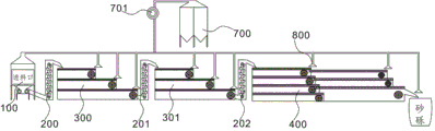
FIG. 1 is a schematic view of the whole processing line of a dust-free, environmental-friendly slag analysis sand making and pulverizing apparatus.
FIG. 2 is a structural diagram of a feeding device of a dust-free, environmental-friendly slag analysis sand making and pulverizing device.
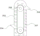
FIG. 3 is a view showing the longitudinal section structure of a lifter of a dust-free, environmental-friendly slag analysis sand making and pulverizing apparatus.
FIG. 4 is a structural diagram of primary and secondary crushers of a dust-free, environmental-friendly slag analysis sand making and pulverizing apparatus.
FIG. 5 is a structural view of a translational powder feeding and sorting machine of a dust-free, environmental-friendly slag analysis sand-making and pulverizing apparatus.
FIG. 6 is a view showing the structure of a spiral conveying pipe of a dust-free, environmental-friendly slag analysis sand making and pulverizing apparatus.
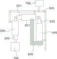
FIG. 7 is a view showing the installation layout of a dust-free, environmental-friendly slag analysis sand making and pulverizing apparatus.
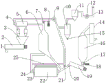
FIG. 8 is a schematic structural view of a dust-free, environmental-friendly slag analysis sand making and pulverizing apparatus.
FIG. 9 is a front view of a dust-free, environmental-friendly slag analysis sand making and pulverizing apparatus.
FIG. 10 is a schematic structural view of a cooling device of a dust-free, environmental-friendly slag analysis sand making and pulverizing apparatus.
FIG. 11 is a detailed view of a material return pipe of a dust-free environment-friendly slag analysis sand making and pulverizing device.
FIG. 12 is a sectional view of a separator of a dust-free, environmental-friendly slag analysis sand-making and pulverizing apparatus.
Reference numerals: the device comprises a feeding device 100, a support column 101, a feeding platform 102, a hopper 103, a feeding spiral conveying support 104, a buffer spring 105, a dustproof curtain 106, a first elevator 200, a second elevator 201, a third elevator 202, an elevator casing 203, a feeding port 204, a discharging port 205, a lifting driving wheel 206, a material containing hopper 207, a primary crusher 300, a secondary crusher 301, a first-layer sieve plate 302, a second-layer sieve plate 303, a third-layer sieve plate 304, a powder feeding plate 305, a crushing driving wheel 306, a first-layer crushing roller 307, a second-layer crushing roller 308, a crushing motor 309, an electromagnetic switch 311, a strong magnet 312, a translational powder feeding separator 411, a first-layer feeding sieve plate 401, a second-layer feeding sieve plate 402, a third-layer feeding sieve plate 403, a sorting powder feeding plate 404, a feeding driving wheel 405, a feeding motor 406, a first-layer receiving sieve 411, a second-layer receiving sieve 412, a receiving powder feeding plate, the device comprises a gravel receiving port 422, a fine powder receiving port 423, a spiral conveying pipe 500, a spiral conveying motor 501, a spiral conveying 502, a powder inlet 503, a powder outlet 504, an anti-blocking cover plate 505, a position sensor 506, a feed back belt 600, a dust removal recovery device 700, a dust removal recovery fan 701, a discharge pipe 1, a first spiral conveying machine 2, a hopper 3, a discharger 4, a discharge box 5, a separator 6, a suction fan 7, a suction motor 8, a first fan 9, a cyclone dust collector 10, a bag-type dust collector 11, a second fan 12, an exhaust pipe 13, a material lifting machine 14, a first air-lock valve 15, a powder bin 16, a rotary control valve 17, a valve motor 18, a second spiral conveying machine 19, a second air-lock valve 20, a third air-lock valve 21, a grinder 22, a packing 23, a cooling spray device 24, a balance pipe 25, a water inlet pipe 241, a water suction pump 242, a spray pipe 243 and a spray head 244.
Detailed Description
The present invention will be described in detail with reference to the accompanying drawings.
In order to make the objects, technical solutions and advantages of the present invention more clearly understood, the following description, with reference to the accompanying drawings and detailed description, clearly and completely describes the technical solutions of the embodiments of the present invention; it is to be understood that the embodiments described are only some of the embodiments of the invention, and not all of them; all other embodiments, which can be derived by a person skilled in the art from the described embodiments of the invention, belong to the scope of protection of the invention.
Referring to fig. 1, 2, 3, 4, 5 and 6, a dust-free environment-friendly slag analysis sand making and pulverizing device comprises a feeding device 100, a support column 101, a feeding platform 102, a hopper 103, a feeding spiral conveying support 104, a buffer spring 105, a first elevator 200, a second elevator 201, a third elevator 202, an elevator casing 203, a feeding port 204, a discharging port 205, a lifting driving wheel 206, a lifting belt 207, a containing hopper 208, a primary crusher 300, a secondary crusher 301, a first-layer sieve plate 302, a second-layer sieve plate 303, a third-layer sieve plate 304, a powder feeding plate 305, a crushing driving wheel 306, a first-stage crushing roller 307, a second-stage crushing roller 308, a crushing motor 309, a translational powder feeding separator 400, a first-stage feeding sieve plate 401, a second-stage feeding sieve plate 402, a third-stage feeding sieve plate 403, a separating powder feeding plate 404, a feeding driving wheel 405, a feeding motor 406, a first-stage receiving sieve 411, The device comprises a material receiving and powder conveying plate 413, a material receiving driving wheel 414, a material receiving motor 415, a material returning and material receiving port 421, a gravel receiving port 422, a fine powder receiving port 423, a spiral conveying pipe 500, a spiral conveying motor 501, a spiral conveying 502, a powder inlet 503, a powder outlet 504, an anti-blocking cover plate 505, a material returning belt 600, a dust removal and recovery device 700 and a dust removal and recovery fan 701; four supporting columns 101 are arranged at four corners below the feeding device 100 to support the whole feeding device, the feeding platform 102 is a slightly inclined plate surface structure which enables raw materials fed into the feeding device 100 to slowly enter a hopper 103, a feeding port is arranged at the rear position of the feeding platform 102, the hopper 103 is connected below the feeding port, the hopper 103 is in a square funnel shape and is convenient for the raw materials to collect and fall down, a feeding screw conveyor is arranged below the hopper 103, a feeding screw conveying support 104 is arranged below the feeding screw conveyor, a buffer spring 105 is arranged at each of four corners of the feeding screw conveying support 104 and can buffer and reduce noise while ensuring the raw materials to stably enter, the feeding device 100 is conveyed to a first elevator 200 through screw conveying and the raw materials are conveyed to the primary crushing device 300 through the first elevator 200, the outside semicircular below in upper end that is of lifting machine 200 be rectangular structure, lifting machine casing 203 below be provided with infundibulate feed inlet 204, lifting machine casing 203 top be provided with the discharge gate 205 of hopper shape, lifting machine casing 203 in the upper and lower position respectively be provided with a promotion drive wheel 206 with the specification, promotion drive wheel 206 drive by driving motor, lifting machine drive wheel 206 connect through elevator belt 207, holding hopper 208 for the cavity fall trapezium structure and be a plurality of evenly be fixed in on elevator belt 207, the outside grinder 300 be equipped with the grinder shell, primary grinder 300 in from top to bottom evenly be provided with one deck sieve board 302, two layers of sieve boards 303, three-layer sieve board 304 and send whitewashed board 305, one deck, two layers, three-layer sieve boards are the mesh design that reduces step by step and can guarantee that graded kibbling slay carries out crushing treatment step by step, the powder feeding plate 305 is a non-porous plate-shaped structure and pushes low-layer fine powder backwards, the first-layer sieve plate, the second-layer sieve plate, the third-layer sieve plate and the powder feeding plate move together through connection and are in contact connection with a crushing driving wheel 306 arranged outside a crusher shell through a vibration shaft, the lengths of the first-layer sieve plate 302, the second-layer sieve plate 303 and the third-layer sieve plate 304 are increased step by step, a first-stage crushing roller 307 is arranged below the tail end of the first-layer sieve plate 302, a second-stage crushing roller 308 is arranged below the tail end of the second-layer sieve plate 303, the crushing rollers are in double-roller design and are connected with a shaft in a crushing driving wheel 36 through a connecting shaft and a belt, the crushing driving wheel 306 is connected with a crushing motor 309 through a belt, the tail end of the primary crusher 3 is provided with a raw material discharging port and a primary powder feeding discharging port corresponding to the third-layer sieve plate 304 and the powder, the primary powder feeding discharge port is connected with a powder feeding port 503 of a spiral conveying pipe 500 with the same structure, the basic structure of the secondary crusher 301 is the same as that of the primary crusher 30, the sizes of the meshes of the sieve plates corresponding to one layer of sieve plate, two layers of sieve plates and three layers of sieve plates and the gaps of the crushing rollers are different, and the meshes are gradually decreased, the gaps of the crushing rollers are gradually decreased, the translational powder feeding separator 400 is designed in a multi-sieve-plate parallel mode, the primary feeding sieve plate 401, the secondary feeding sieve plate 402, the tertiary feeding sieve plate 403 and the separating powder feeding plate 404 are arranged in the front half part of the translational powder feeding separator 400 from top to bottom and are connected with a feeding driving wheel 405 arranged outside a shell of the translational powder feeding separator through vibration shafts in a contact mode, the feeding driving wheel 405 is connected with a feeding motor 406 through a belt, the primary material receiving sieve 411, the secondary material receiving sieve 412 and the material receiving powder feeding plate 413 are arranged in the rear half part of the translational powder feeding separator 4 from, and realize the joint motion through connecting and connect through the vibration shaft contact with the material receiving drive wheel 414 that sets up outside the translation powder feeding sorter casing, the material receiving drive wheel 414 be connected with receiving motor 415 through the belt, the one-level receive material sieve 411, second grade receive material sieve 412, receive the material and send powder board 413 to correspond second grade pay-off sieve plate 402 respectively, tertiary pay-off sieve plate 403, select separately send powder board 404 parallel slightly less than the former design can sieve the processing after the slag and finally realize the tertiary processing after material of feed back slag, finished product gravel and fine powder, translation powder feeding sorter 4 end correspond one-level receive material sieve 411, second grade receive material sieve 412, send powder board 413 to be provided with feed back material receiving mouth 421, gravel receiving mouth 422 and fine powder receiving mouth 423 respectively, feed back material receiving mouth 421 set up in the top of feed back belt 600 initiating terminal, gravel interface 422 directly send out the gravel finished product, the fine powder connect material mouth 423 to go into with structure auger delivery 500's powder inlet 503, auger delivery 500 be hollow cuboid tubular structure, auger delivery 500 initiating terminal be provided with auger delivery motor 501, auger delivery motor 501 be connected with auger delivery 502 in the auger delivery 500, auger delivery 5 be provided with powder inlet 503 near the motor end on the body, auger delivery 5 pipe body below of keeping away from the motor end be provided with powder outlet 504, auger delivery 500 directly over powder outlet 504 on be provided with apron 505 and be connected with auger delivery 500 through the pin joint mode and be provided with buckle and auger delivery 500 lock joint at the other end, dust removal recovery unit 700 be provided with dust removal recovery fan 701 outward, connect through each dust removal wind gap of pipeline.
Referring to fig. 7, an installation layout of a slag dust-free environment-friendly analysis sand-making and pulverizing device, wherein a feeding device 100 is connected with a first elevator 200 through a spiral conveying pipe 500, the first elevator 200 is in contact connection with a layer of sieve plate 301 of a primary crusher 300, the primary crusher 300 is in contact connection with the uppermost sieve plate of a secondary crusher 301 through a second elevator 201, the secondary crusher 301 is in contact connection with a first feeding plate 401 of a translational powder-feeding separator 400 through a third elevator 202, a return material receiving port 421 of the translational powder-feeding separator 400 is in contact connection with the uppermost sieve plate of a secondary crusher 301 through a return material belt 600, and the bottommost powder-feeding mechanisms of the primary crusher 300, the secondary crusher 301 and the translational powder-feeding separator 400 converge and send out fine powder through the spiral conveying pipe 500; the upper part of a material lifting machine 14 is hermetically connected with the upper part of a powder bin 16 through a pipeline, the material lifting machine 14 is used for lifting materials, the powder bin 16 is used for storing powder, the lower end of the powder bin 16 is hermetically connected with a second screw conveyer 19 through a pipeline, a rotary control valve 17 is fixedly arranged on the pipeline between the powder bin 16 and the second screw conveyer 19, the rotary control valve 17 is meshed with a valve motor 18 through a gear, the output end of the second screw conveyer 19 is hermetically connected with a feed inlet of a grinding machine 22 through a pipeline, the pipeline hermetically connected with a discharge outlet of the grinding machine 22 extends into a separator 6, the separator 6 is used for screening and separating coarse and fine powder, the lower end outlet of the separator 6 is hermetically connected with the feed inlet of the grinding machine 22 through a pipeline, a suction fan 7 is arranged at the upper end outlet of the separator 6, the suction fan 7 is connected with a suction motor 8 through a belt wheel, and, the lower surface of a discharging box 5 is hermetically connected with a discharger 4, a hopper 3 is arranged below the discharger 4, the hopper 3 is used for receiving powder, the hopper 3 is fixedly arranged on a first screw conveyer 2, the first screw conveyer 2 and a second screw conveyer 19 are respectively used for conveying the powder, the lower surface of the output end of the first screw conveyer 2 is fixedly provided with a discharging pipe 1, one side of the discharging box 5, far away from a separator 6, is hermetically connected with a suction inlet of a first fan 9 through a pipeline, an air outlet of the first fan 9 is hermetically connected with a feed inlet of a mill 22 and a feed inlet of a cyclone dust collector 10 through pipelines, a third air-closing valve 21 is hermetically connected on the pipeline between the first fan 9 and the mill 22, a discharge outlet of the mill 22 is hermetically connected with an air outlet of the fan through a balance pipe 25, the lower end of the cyclone dust collector 10 is fixedly provided with a first air-closing valve 15, and an air outlet at the, an air outlet of the bag-type dust collector 11 is hermetically connected with an air inlet of a second fan 12 through a pipeline, an air outlet of the second fan 12 is hermetically connected with an exhaust pipe 13, a cooling spray device 24 is arranged above the mill 22, the cooling spray device 24 is used for cooling the mill 22, the cooling spray device 24 comprises a water inlet pipe 241, a water suction pump 242, a spray pipe 243 and a spray head 244, the input end of the water suction pump 242 is hermetically connected with the water inlet pipe 241, the output end of the water suction pump 242 is hermetically connected with the spray pipe 243, the lower part of the spray pipe 243 is hermetically connected with the spray head 244, and the position of; the second screw conveyor 19 feeds materials obliquely upwards; the number of the discharging devices 4 is 2-4; the number of the spray pipes 243 is 15-30; the first screw conveyor 2 and the second screw conveyor 19 each include a rotary motor, a screw blade, and a conveying box; the material lifting machine 14 comprises a material lifting motor, a transmission roller, a transmission belt and a hopper 3; packing 23 are arranged at two ends of the grinding machine 22, so that dynamic sealing of the grinding machine 22 is realized, and sealing quality is improved.
The feed back pipe 26 is internally provided with a feed back valve 261 and a feed back valve 264, the feed back valve 261 and the feed back valve 264 are both in an oval design internally tangent to the wall of the feed back pipe, the feed back valve 261 and the feed back valve 264 are respectively and correspondingly fixedly connected with a driving rod 262 and a driving rod 265 in an integrated manner, the driving rod 262 and the driving rod 265 are both in double-rod pin joint connection, and a weight 263 and a weight 266 are arranged at the lower part of a second rod.
The utility model discloses a theory of operation is: the material lifting machine 14 extracts materials to enter a powder bin 16, a valve motor 18 is started to open a rotary control valve 17, a second spiral conveyor 19 is started to convey the materials, a first fan 9 and a second fan 12 are started to form loop airflow to drive powder to operate, a second air-lock valve 20 is opened, the powder enters a mill 22 from the second spiral conveyor 19, the powder enters a separator 6 after being ground, both ends of the mill 22 are subjected to dynamic sealing through packing 23 to improve the sealing performance, an air suction motor 8 is started to drive a suction fan 7 to suck fine powder upwards, the coarse powder falls back to a feed inlet of the mill 22 to be ground again, the fine powder enters a discharge box 5, the fine powder is discharged through a discharger 4, a hopper 3 is collected, the fine powder is fed through a first spiral conveyor 2 and discharged from a discharge pipe 1, the fine powder entering the discharge box 5 enters a cyclone dust collector 10 along with gas through the first fan 9 to remove dust, and then is purified through a bag dust, the gas is discharged from the gas discharge pipe 13, and the pressure difference between the two ends of the mill 22 is balanced by the balance pipe 25 in the process, so that the powder passes through the mill 22 slowly, and the grinding time is prolonged.
The feeding end of the feeding device 100 is provided with a dustproof curtain 106 fixed on the upper part of the integral device frame body, the dustproof curtain 106 is made of soft plastic with a plurality of pieces, and the feeding bin and the external space can not be fed.
The 3 casings of primary crusher on be provided with electromagnetic switch 301, crushing drive wheel 36 on be provided with strong magnet 302, both cooperate mutually to realize the effect of control crushing motor 39, electromagnetic switch 301 can set up timing controller, if detect strong magnet 302 in the allotted time and can control crushing motor 309 outage to make the whole power transmission structure stop work of primary crusher 300, guarantee that the material can not continue the pay-off to cause piling up of material under the condition that crushing roller blocked.
The positions of the crushing roller, the discharge hole and the feed inlet are all provided with dust removal air ports 800, and the dust removal air ports are connected with a dust removal recovery fan 701 through hoses, so that the dust-free processing is maximized in the operation process of the whole device.
The mouth of the feed pipe in the separator 600 is provided with a louvered analysis plate 601.
The above embodiments are only used for illustrating the technical solutions of the present invention and not for limiting, and other modifications or equivalent replacements made by the technical solutions of the present invention by those of ordinary skill in the art should be covered within the scope of the claims of the present invention as long as they do not depart from the spirit and scope of the technical solutions of the present invention.
Claims (10)
1. The utility model provides a dustless environmental protection analysis system sand powder process device of slay which characterized in that: comprises a feeding device, a supporting column, a feeding platform, a hopper, a feeding spiral conveying support, a buffer spring, a first elevator, a second elevator, a third elevator casing, a feeding port, a discharging port, a lifting driving wheel, a lifting belt, a containing hopper, a primary crusher, a secondary crusher, a first layer sieve plate, a second layer sieve plate, a third layer sieve plate, a powder conveying plate, a crushing driving wheel, a first crushing roller, a second crushing roller, a crushing motor, a translational powder conveying separator, a first layer feeding sieve plate, a second layer feeding sieve plate, a third layer feeding sieve plate, a sorting powder conveying plate, a feeding driving wheel, a feeding motor, a first receiving sieve, a second receiving sieve, a receiving powder conveying plate, a receiving driving wheel, a receiving motor, a returned material receiving port, a gravel receiving port, a fine powder receiving port, a spiral conveying pipe, a spiral conveying motor, spiral conveying, a powder feeding port, a powder discharging port, The device comprises a dust removal recovery device, a dust removal recovery fan, a gravel interface, a material lifting machine, a powder bin, a second screw conveyor, a rotary control valve, a valve motor, a separator, a suction fan, a suction motor, a material discharging box, a discharger, a first screw conveyor, a discharging pipe, a first fan, a cyclone dust collector, a third air-closing valve, a balance pipe, a first air-closing valve, a bag-type dust collector, a second fan, an exhaust pipe and a cooling spray device; four corners below the feeding device are provided with four support columns which support the whole feeding device, the feeding platform is of a slightly-inclined plate surface structure which can enable raw materials fed into the feeding device to slowly enter a hopper, a feeding hole is formed in the rear position of the feeding platform, the hopper is connected below the feeding hole and is in a square funnel shape so that the raw materials can be conveniently collected and fall down, feeding spiral conveying is arranged below the hopper, a feeding spiral conveying support is arranged below the feeding spiral conveying support, four corners of the feeding spiral conveying support are respectively provided with a buffer spring which can buffer and reduce noise while ensuring the raw materials to stably enter, the feeding device is conveyed to a lifting machine through spiral conveying and conveys the raw materials to a primary crushing device through the lifting machine, and the outer part of the lifting machine is of a structure with a semicircular upper end and a rectangular lower part, lifting machine casing below be provided with the feed inlet of infundibulate, lifting machine casing top be provided with the discharge gate of funnel shape, lifting machine casing in the upper and lower position respectively be provided with a promotion drive wheel with the specification, the promotion drive wheel drive by driving motor, the lifting machine drive wheel pass through the elevator belt and connect, holding hopper fall trapezoidal structure for cavity and be a plurality of evenly be fixed in on the elevator belt, the outside rubbing crusher shell that is equipped with of primary crusher, primary crusher in from top to bottom evenly be provided with one deck sieve, two layers of sieve, three-layer sieve and send the powder board, one deck, two layers, three-layer sieve are the sieve mesh design that reduces step by step and can guarantee that hierarchical kibbling slay carries out crushing treatment step by step, send the powder board to push back the low level for sclausura eye platelike structure, and one deck, two layers of, The three layers of sieve plates and the powder feeding plate are connected to realize common movement and are in contact connection with a crushing driving wheel arranged outside a shell of the crusher through a vibration shaft, the lengths of the first layer of sieve plate, the second layer of sieve plate and the third layer of sieve plate are gradually increased, a first-level crushing roller is arranged below the tail end of the first layer of sieve plate, a second-level crushing roller is arranged below the tail end of the second layer of sieve plate, the crushing rollers are in double-roller design and are connected with a shaft in the crushing driving wheel through a connecting shaft and a belt, the crushing driving wheel is connected with a crushing motor through the belt, a raw material discharge port and a primary powder feeding discharge port are designed at the tail end of the primary crusher corresponding to the third layer of sieve plate and the powder feeding plate, the raw material discharge port is connected with a feed port of a lifting machine II with the same structure, the primary powder feeding discharge port is connected with a, the sizes of the holes of the sieve plates corresponding to the first layer of sieve plate, the second layer of sieve plate and the third layer of sieve plate and the gaps of the crushing rollers are different and are designed to gradually decrease the holes and gradually decrease the gaps of the crushing rollers, the translational powder feeding separator is designed in parallel with a plurality of sieve plates, the first-stage feeding sieve plate, the second-stage feeding sieve plate, the third-stage feeding sieve plate and the separating powder feeding plate are arranged in the front half part of the translational powder feeding separator from top to bottom and are connected with a feeding driving wheel arranged outside the shell of the translational powder feeding separator in a contact way through a vibration shaft, the feeding driving wheel is connected with a feeding motor through a belt, the first-stage receiving sieve, the second-stage receiving sieve and the receiving powder feeding plate are arranged in the rear half part of the translational powder feeding separator from top to bottom and are connected with the receiving driving wheel arranged outside the shell of the translational powder feeding separator in a contact, connect the material drive wheel to be connected with connecing the material motor through the belt, the one-level connect material sieve, the second grade connect material sieve, connect material to send the powder board to correspond second grade pay-off sieve 402, tertiary pay-off sieve, select separately and send the powder board design and can sieve the processing after slay and finally realize the tertiary processing back material of feed back slay, finished product gravel and farine a little bit less than the former, the translation send powder sorter end correspond one-level connect material sieve, second grade connect material sieve, connect material to send the powder board and be provided with feed back material receiving opening, gravel material receiving opening and farine material receiving opening respectively, feed back material receiving opening set up in the top of feed back belt initiating terminal, the gravel interface directly send out the gravel finished product, the farine material receiving opening go into the powder inlet of the same structure spiral delivery pipe, spiral delivery pipe be hollow rectangular tubular structure, spiral delivery pipe initiating terminal be provided with spiral delivery motor, the spiral conveying motor is connected with spiral conveying in the spiral conveying pipe, a powder inlet is arranged on the end, close to the motor, of the spiral conveying pipe, a powder outlet is arranged below the end, far away from the motor, of the spiral conveying pipe, an anti-blocking cover plate is arranged on the spiral conveying pipe right above the powder outlet and connected with the spiral conveying pipe in a pin joint mode, a buckle is arranged at the other end of the spiral conveying pipe and fastened with the spiral conveying pipe, a dedusting recovery fan is arranged outside the dedusting recovery device and connected with each dedusting air port through a pipeline, the feeding device is connected with a first lifting machine through the spiral conveying pipe, the first lifting machine is in contact connection with one layer of sieve plate of a primary crusher, the primary crusher is in contact connection with the uppermost layer of sieve plate of a secondary crusher through a second lifting machine, and the secondary crusher is in contact connection with one-level feeding plate of a translational powder feeding sorting machine, the feed back material receiving port of the translational powder feeding sorting machine is in contact connection with the topmost sieve plate of the secondary crusher through a feed back belt, and the primary crusher, the secondary crusher and the bottommost powder feeding mechanism of the translational powder feeding sorting machine are converged through a spiral conveying pipe and send out fine powder; the upper part of the material lifting machine is connected with the upper part of the powder bin in a sealing way through a pipeline, the lower end of the powder bin is connected with the second screw conveyer in a sealing way through a pipeline, the rotary control valve is fixedly arranged on the pipeline between the powder bin and the second screw conveyer, the rotary control valve is meshed with the valve motor through a gear, the output end of the second screw conveyer is connected with the mill feed inlet in a sealing way through a pipeline, the pipeline connected with the mill discharge outlet in a sealing way extends into the separator, the outlet at the lower end of the separator is connected with the mill feed inlet in a sealing way through a pipeline, the outlet at the upper end of the separator is provided with the suction fan, the suction fan is connected with the suction motor through a belt wheel, the outlet at the upper end of the separator is connected with the discharge box in a sealing way through a pipeline, and the lower surface of the, the hopper is arranged below the discharger, the hopper is fixedly arranged on the first spiral conveyer, the discharging pipe is fixedly arranged on the lower surface of the output end of the first spiral conveyer, one side of the discharging box, which is far away from the separator, is in sealing connection with the first fan air suction opening through a pipeline, the first fan air outlet is respectively in sealing connection with the mill feed inlet and the cyclone dust collector feed inlet through pipelines, the third air-closing valve is in sealing connection with the pipeline between the first fan and the mill, the mill discharge opening is in sealing connection with the fan air outlet through the balance pipe, the first air-closing valve is fixedly arranged at the lower end of the cyclone dust collector, the air outlet at the upper end of the cyclone dust collector is in sealing connection with the air inlet of the cloth bag dust collector through a pipeline, and the air outlet of the cloth bag dust collector is in sealing connection with the air inlet of the second fan, second fan air outlet sealing connection has the blast pipe, the mill top is provided with cooling spray set, cooling spray set includes inlet tube, suction pump, shower and shower nozzle, suction pump input sealing connection has the inlet tube, suction pump output sealing connection has the shower, shower below sealing connection has the shower, the shower position with correspond from top to bottom the mill.
2. The dust-free and environment-friendly slag analysis sand making and pulverizing device as claimed in claim 1, wherein: the feeding device is provided with a dust removal air port at the top of the integral device.
3. The dust-free and environment-friendly slag analysis sand making and pulverizing device as claimed in claim 1, wherein: the feeding end of the feeding device is provided with a dustproof curtain fixed on the upper part of the integral device frame body, and the dustproof curtain is made of soft plastic materials with a plurality of pieces.
4. The dust-free and environment-friendly slag analysis sand making and pulverizing device as claimed in claim 1, wherein: the primary crusher shell is provided with an electromagnetic switch, the crushing driving wheel is provided with a strong magnet, and the two parts are matched with each other to realize the effect of controlling the crushing motor.
5. The dust-free and environment-friendly slag analysis sand making and pulverizing device as claimed in claim 1, wherein: the spiral conveying pipe body of the spiral conveying pipe close to the spiral conveying motor is provided with a position sensor for detecting the condition of materials in the pipe and controlling the spiral conveying motor.
6. The apparatus of claim 1, wherein the apparatus comprises: and the second spiral conveyor feeds materials obliquely upwards.
7. The apparatus of claim 1, wherein the apparatus comprises: the first screw conveyor and the second screw conveyor both comprise a rotary motor, a screw blade and a conveying box.
8. The apparatus of claim 1, wherein the apparatus comprises: the material lifting machine comprises a material lifting motor, a transmission roller, a transmission belt and a hopper.
9. The apparatus of claim 1, wherein the apparatus comprises: packing is arranged at both ends of the mill.
10. The apparatus of claim 1, wherein the apparatus comprises: a first material return valve and a second material return valve are arranged in the material return pipe, the first material return valve and the second material return valve are both in an oval design internally tangent to the pipe wall of the material return pipe, the first material return valve and the second material return valve are respectively and correspondingly fixedly connected with a first driving rod and a second driving rod in an integrated manner, the first driving rod and the second driving rod are both in double-rod pin joint connection, and a first heavy block and a second heavy block are arranged at the lower part of a second rod; the mouth of the feed pipe in the separator is provided with a louvered analysis plate.
Priority Applications (1)
| Application Number | Priority Date | Filing Date | Title |
|---|---|---|---|
| CN201921085159.2U CN210875757U (en) | 2019-07-12 | 2019-07-12 | Dustless environmental protection analysis system sand powder process device of slay |
Applications Claiming Priority (1)
| Application Number | Priority Date | Filing Date | Title |
|---|---|---|---|
| CN201921085159.2U CN210875757U (en) | 2019-07-12 | 2019-07-12 | Dustless environmental protection analysis system sand powder process device of slay |
Publications (1)
| Publication Number | Publication Date |
|---|---|
| CN210875757U true CN210875757U (en) | 2020-06-30 |
Family
ID=71333370
Family Applications (1)
| Application Number | Title | Priority Date | Filing Date |
|---|---|---|---|
| CN201921085159.2U Active CN210875757U (en) | 2019-07-12 | 2019-07-12 | Dustless environmental protection analysis system sand powder process device of slay |
Country Status (1)
| Country | Link |
|---|---|
| CN (1) | CN210875757U (en) |
Cited By (4)
| Publication number | Priority date | Publication date | Assignee | Title |
|---|---|---|---|---|
| CN110216004A (en) * | 2019-07-12 | 2019-09-10 | 秦林强 | A kind of slag dustless environment protecting analysis sand fuel pulverizing plant processed |
| CN112808378A (en) * | 2020-12-30 | 2021-05-18 | 胡志刚 | Waste recovery processing device for construction |
| CN113996532A (en) * | 2021-10-26 | 2022-02-01 | 阜阳丰达机电设备有限公司 | Blade screening and recutting device |
| CN117065902A (en) * | 2023-10-16 | 2023-11-17 | 福建美斯拓机械设备有限公司 | Multistage broken sand making machine |
-
2019
- 2019-07-12 CN CN201921085159.2U patent/CN210875757U/en active Active
Cited By (6)
| Publication number | Priority date | Publication date | Assignee | Title |
|---|---|---|---|---|
| CN110216004A (en) * | 2019-07-12 | 2019-09-10 | 秦林强 | A kind of slag dustless environment protecting analysis sand fuel pulverizing plant processed |
| CN110216004B (en) * | 2019-07-12 | 2024-03-12 | 秦林强 | Dust-free environment-friendly slag analysis sand making and pulverizing device |
| CN112808378A (en) * | 2020-12-30 | 2021-05-18 | 胡志刚 | Waste recovery processing device for construction |
| CN113996532A (en) * | 2021-10-26 | 2022-02-01 | 阜阳丰达机电设备有限公司 | Blade screening and recutting device |
| CN117065902A (en) * | 2023-10-16 | 2023-11-17 | 福建美斯拓机械设备有限公司 | Multistage broken sand making machine |
| CN117065902B (en) * | 2023-10-16 | 2023-12-15 | 福建美斯拓机械设备有限公司 | Multistage broken sand making machine |
Similar Documents
| Publication | Publication Date | Title |
|---|---|---|
| CN210875757U (en) | Dustless environmental protection analysis system sand powder process device of slay | |
| CN107321434A (en) | A kind of low Stone processing equipment | |
| CN102211854B (en) | Dry process scale continuous production process of quartz sand | |
| CN109482627B (en) | Construction waste treatment line and treatment method | |
| CN110280567A (en) | A kind of building waste specification recovery processing device | |
| CN102328360A (en) | Polyethylene pipe broken material or drop material sorting and separating device | |
| CN109967494A (en) | A kind of process and system handling building waste | |
| CN110216004B (en) | Dust-free environment-friendly slag analysis sand making and pulverizing device | |
| CN112317094A (en) | Preparation system of waste concrete reclaimed sand powder | |
| CN117065902B (en) | Multistage broken sand making machine | |
| CN215611805U (en) | Production facility that mining barren rock preparation aggregate was with having high-efficient dust removal | |
| CN115400825A (en) | Production equipment and process with efficient dust removal function for preparing aggregate from mining waste rocks | |
| CN208928354U (en) | Device for discharging of crusher | |
| CN209191063U (en) | Plastic cleaning equipment | |
| CN112317515A (en) | Dust removal recovery device and dust removal recovery method for spray tower | |
| CN210171639U (en) | Dry powder machine system sand apparatus for producing | |
| CN201684884U (en) | Foundry sand and furnace slag recovering treatment equipment | |
| CN101862810B (en) | Cast used sand and slag recycling equipment | |
| CN217780195U (en) | A unload grain system for feed production | |
| CN213671073U (en) | Dust removal and recovery device for spray tower | |
| CN212370350U (en) | Preparation system of waste concrete reclaimed sand powder | |
| CN108246477A (en) | A kind of sand production line processed | |
| CN104399667B (en) | Stainless steel slag sorting device and stainless steel slag sorting method | |
| CN207308877U (en) | A kind of foundry scrap separating and reclaiming device | |
| CN110893369B (en) | Screening and grinding production line system for copper slag materials |
Legal Events
| Date | Code | Title | Description |
|---|---|---|---|
| GR01 | Patent grant | ||
| GR01 | Patent grant |