CN210849440U - Machining detection device - Google Patents
Machining detection device Download PDFInfo
- Publication number
- CN210849440U CN210849440U CN201921852641.4U CN201921852641U CN210849440U CN 210849440 U CN210849440 U CN 210849440U CN 201921852641 U CN201921852641 U CN 201921852641U CN 210849440 U CN210849440 U CN 210849440U
- Authority
- CN
- China
- Prior art keywords
- straight
- bar
- spout
- workbench
- rod
- Prior art date
- Legal status (The legal status is an assumption and is not a legal conclusion. Google has not performed a legal analysis and makes no representation as to the accuracy of the status listed.)
- Expired - Fee Related
Links
Images

Abstract
The utility model discloses a machining detection device, comprises a workbench, the workstation is installed on the organism, workstation one side is equipped with the mounting panel, the mounting panel right side is equipped with buffer gear, the last fixed plate that is equipped with of buffer gear, the fixed plate bottom is equipped with the spout, be equipped with the slider on the spout, be equipped with the telescopic link on the slider, the workstation opposite side has the shape pole of falling L through recess swing joint, the recess both sides are equipped with the dog, the shape pole of falling L includes first straight-bar and second straight-bar, first straight-bar is installed on the workstation, first straight-bar links to each other with the second straight-bar is perpendicular, first straight-bar left side is equipped with electric telescopic handle, the electric telescopic handle other end is equipped with the push pedal, the second straight-bar has spout one, be equipped with slider one on the spout, be. The utility model has simple structure and convenient use, and the electric push rod and the telescopic cylinder which are arranged respectively detect the workpiece through the push plate and the press plate, thereby reducing the labor force and ensuring accurate detection; through the buffer gear who sets up, avoid producing the collision when detecting the work piece, guarantee that the work piece does not receive the damage.
Description
Technical Field
The utility model relates to a machining equipment technical field specifically is a machining detection device.
Background
Machining refers to a process of changing the outer dimensions or properties of a workpiece by a mechanical device, and is classified into cutting and pressing according to differences in machining modes. In the machining process, the size and the thickness of a workpiece are detected, and when a common device is used for detecting, the error rate of a detection result is high due to the fact that operation is troublesome and the error rate of manual calibration is high.
SUMMERY OF THE UTILITY MODEL
An object of the utility model is to provide a machining detection device to solve the problem that proposes among the above-mentioned background art.
In order to achieve the above object, the utility model provides a following technical scheme: the utility model provides a machining detection device, comprises a workbench, the workstation is installed on the organism, workstation one side is equipped with the mounting panel, the mounting panel right side is equipped with buffer gear, the last fixed plate that is equipped with of buffer gear, the fixed plate bottom is equipped with the spout, be equipped with the slider on the spout, be equipped with the telescopic link on the slider, the workstation opposite side has down L shape pole through recess swing joint, the recess both sides are equipped with the dog, it includes first straight-bar and second straight-bar to fall L shape pole, first straight-bar is installed on the workstation, first straight-bar links to each other with the second straight-bar is perpendicular, first straight-bar left side is equipped with electric telescopic handle, the electric telescopic handle other end is equipped with the push pedal, the second straight-bar has and is equipped with spout one, be equipped with.
Preferably, the buffer mechanism comprises two side return springs, one side of each side return spring is connected with the mounting plate, the other side of each side return spring is connected with the fixing plate, and an electric push rod is arranged between the two side return springs.
Preferably, the workbench and the fixing plate are provided with scale marks.
Preferably, the elastic element is made of a rubber material.
Compared with the prior art, the beneficial effects of the utility model are that: the utility model has simple structure and convenient use, and the electric push rod and the telescopic cylinder which are arranged respectively detect the workpiece through the push plate and the press plate, thereby reducing the labor force and ensuring accurate detection; through the buffer gear who sets up, avoid producing the collision when detecting the work piece, guarantee that the work piece does not receive the damage.
Drawings
Fig. 1 is a schematic structural view of the present invention;
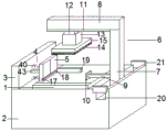
fig. 2 is a schematic view of the three-dimensional structure of the present invention.
Detailed Description
The technical solutions in the embodiments of the present invention will be described clearly and completely with reference to the accompanying drawings in the embodiments of the present invention, and it is obvious that the described embodiments are only some embodiments of the present invention, not all embodiments. Based on the embodiments in the present invention, all other embodiments obtained by a person skilled in the art without creative work belong to the protection scope of the present invention.
Referring to fig. 1-2, the present invention provides a technical solution: a machining detection device comprises a workbench 1, the workbench 1 is mounted on a machine body 2, a mounting plate 3 is arranged on one side of the workbench 1, a buffer mechanism 4 is arranged on the right side of the mounting plate 3, a fixing plate 5 is arranged on the buffer mechanism 4, a sliding groove 17 is arranged at the bottom of the fixing plate 5, a sliding block 18 is arranged on the sliding groove 17, a telescopic rod 19 is arranged on the sliding block 18, an inverted L-shaped rod 6 is movably connected to the other side of the workbench 1 through a groove 20, stop blocks 21 are arranged on two sides of the groove 20, the inverted L-shaped rod 6 comprises a first straight rod 7 and a second straight rod 8, the first straight rod 7 is mounted on the workbench 1, the first straight rod 7 is vertically connected with the second straight rod 8, an electric telescopic rod 9 is arranged on the left side of the first straight rod 7, a push plate 10 is arranged at the other end of the electric telescopic rod 9, a pressure plate 15 is arranged below the telescopic cylinder 13, and an elastic element 14 is arranged below the pressure plate 15.
The utility model discloses in, buffer gear 4 includes both sides reset spring 40, and both sides reset spring 40 one side links to each other with mounting panel 3, and the opposite side links to each other with fixed plate 5, is equipped with electric push rod 43 between the reset spring 40 of both sides.
The utility model discloses in, be equipped with the scale mark on workstation 1 and the fixed plate 5.
In the present invention, the elastic element 14 is made of rubber material.
The working principle is as follows: place the work piece on the workstation, work piece one side offsets with the fixed plate, removes the telescopic link according to the work piece size, fixes the work piece, then promotes the push pedal through electric telescopic handle, and rethread telescopic cylinder moves the clamp plate downwards, measures the size and the thickness of work piece through the scale mark on workstation and the fixed plate.
To sum up, the beneficial effects of the utility model are that: the utility model has simple structure and convenient use, and the electric push rod and the telescopic cylinder which are arranged respectively detect the workpiece through the push plate and the press plate, thereby reducing the labor force and ensuring accurate detection; through the buffer gear who sets up, avoid producing the collision when detecting the work piece, guarantee that the work piece does not receive the damage.
Although embodiments of the present invention have been shown and described, it will be appreciated by those skilled in the art that changes, modifications, substitutions and alterations can be made in these embodiments without departing from the principles and spirit of the invention, the scope of which is defined in the appended claims and their equivalents.
Claims (4)
1. The utility model provides a machining detection device, includes workstation (1), its characterized in that: the workbench (1) is installed on a machine body (2), a mounting plate (3) is arranged on one side of the workbench (1), a buffer mechanism (4) is arranged on the right side of the mounting plate (3), a fixing plate (5) is arranged on the buffer mechanism (4), a sliding groove (17) is arranged at the bottom of the fixing plate (5), a sliding block (18) is arranged on the sliding groove (17), a telescopic rod (19) is arranged on the sliding block (18), an inverted L-shaped rod (6) is movably connected to the other side of the workbench (1) through a groove (20), stop blocks (21) are arranged on two sides of the groove (20), the inverted L-shaped rod (6) comprises a first straight rod (7) and a second straight rod (8), the first straight rod (7) is installed on the workbench (1), the first straight rod (7) is vertically connected with the second straight rod (8), an electric telescopic rod (9) is arranged on the left side of the, the electric telescopic handle (9) other end is equipped with push pedal (10), second straight-bar (8) have been equipped with spout one (11), be equipped with slider one (12) on spout one (11), be equipped with telescopic cylinder (13) on slider one (12), telescopic cylinder (13) have clamp plate (15), clamp plate (15) have elastic element (14).
2. A machining detection apparatus according to claim 1, characterized in that: buffer gear (4) include both sides reset spring (40), both sides reset spring (40) one side links to each other with mounting panel (3), and the opposite side links to each other with fixed plate (5), both sides be equipped with electric push rod (43) between reset spring (40).
3. A machining detection apparatus according to claim 1, characterized in that: and scale marks are arranged on the workbench (1) and the fixed plate (5).
4. A machining detection apparatus according to claim 2, characterized in that: the elastic element (14) is made of rubber materials.
Priority Applications (1)
| Application Number | Priority Date | Filing Date | Title |
|---|---|---|---|
| CN201921852641.4U CN210849440U (en) | 2019-10-31 | 2019-10-31 | Machining detection device |
Applications Claiming Priority (1)
| Application Number | Priority Date | Filing Date | Title |
|---|---|---|---|
| CN201921852641.4U CN210849440U (en) | 2019-10-31 | 2019-10-31 | Machining detection device |
Publications (1)
| Publication Number | Publication Date |
|---|---|
| CN210849440U true CN210849440U (en) | 2020-06-26 |
Family
ID=71299475
Family Applications (1)
| Application Number | Title | Priority Date | Filing Date |
|---|---|---|---|
| CN201921852641.4U Expired - Fee Related CN210849440U (en) | 2019-10-31 | 2019-10-31 | Machining detection device |
Country Status (1)
| Country | Link |
|---|---|
| CN (1) | CN210849440U (en) |
Cited By (1)
| Publication number | Priority date | Publication date | Assignee | Title |
|---|---|---|---|---|
| CN117470824A (en) * | 2023-12-27 | 2024-01-30 | 西安石油大学 | Fluorescent probe device with high-sensitivity detection |
-
2019
- 2019-10-31 CN CN201921852641.4U patent/CN210849440U/en not_active Expired - Fee Related
Cited By (1)
| Publication number | Priority date | Publication date | Assignee | Title |
|---|---|---|---|---|
| CN117470824A (en) * | 2023-12-27 | 2024-01-30 | 西安石油大学 | Fluorescent probe device with high-sensitivity detection |
Similar Documents
| Publication | Publication Date | Title |
|---|---|---|
| CN103753309B (en) | Irregularly shaped object clamping tooling | |
| CN204413659U (en) | Regulate the multi-purpose fixture of clamping face | |
| CN207894381U (en) | Worm shaft inspecting device of symmetry of key groove based on machine vision | |
| CN202803923U (en) | Bending die with movable female die | |
| CN210849440U (en) | Machining detection device | |
| CN104647457B (en) | A kind of cutting clamping device | |
| CN210773746U (en) | Utensil is examined to door sealing strip | |
| CN203843962U (en) | Multi-point measurement device of wooden door processing machine | |
| CN204565642U (en) | Mould is from reducing grip device | |
| CN216049757U (en) | Workpiece height detection pressing mechanism | |
| CN204525610U (en) | A kind of cutting clamping device | |
| CN213080738U (en) | Milling clamping device | |
| CN211277423U (en) | Portable quick adjustable fixture for machining | |
| CN211192667U (en) | Included angle welding tool | |
| CN204412943U (en) | Movable feeding clip mechanism is used in a kind of bender | |
| CN207622633U (en) | A kind of shaving razor handle Multifunctional check tool | |
| CN216245977U (en) | Utensil is examined to measuring tool stamping workpiece has | |
| CN216245997U (en) | Gasket thickness measuring machine | |
| CN216308831U (en) | Cigarette paper specification size rapid survey frock | |
| CN204700581U (en) | A kind of retaining mechanism | |
| CN104827304A (en) | Locking mechanism | |
| CN215248068U (en) | Harmless material module of getting with locate function | |
| CN104070561A (en) | Deflection mechanism of oblique cutting saw | |
| CN210154560U (en) | Flexible detection device for shaft parts | |
| CN215658281U (en) | Linear cutting clamp |
Legal Events
| Date | Code | Title | Description |
|---|---|---|---|
| GR01 | Patent grant | ||
| GR01 | Patent grant | ||
| CF01 | Termination of patent right due to non-payment of annual fee |
Granted publication date: 20200626 Termination date: 20201031 |
|
| CF01 | Termination of patent right due to non-payment of annual fee |