CN210848930U - Auxiliary clamp for rapid welding of robot - Google Patents
Auxiliary clamp for rapid welding of robot Download PDFInfo
- Publication number
- CN210848930U CN210848930U CN201921018460.1U CN201921018460U CN210848930U CN 210848930 U CN210848930 U CN 210848930U CN 201921018460 U CN201921018460 U CN 201921018460U CN 210848930 U CN210848930 U CN 210848930U
- Authority
- CN
- China
- Prior art keywords
- auxiliary
- robot
- welding
- leg
- supporting leg
- Prior art date
- Legal status (The legal status is an assumption and is not a legal conclusion. Google has not performed a legal analysis and makes no representation as to the accuracy of the status listed.)
- Active
Links
Images


Abstract
The utility model relates to an intelligence manufacture equipment technical field, specifically speaking relates to a quick welding auxiliary clamp of robot. Comprises a rotary platform and a welding auxiliary clamp assembly which is rotationally arranged on the rotary platform, the welding auxiliary clamp assembly comprises a rotary table connected with the rotary platform and a main supporting leg arranged on the rotary table, the main supporting leg is vertically arranged on one side of the turntable far away from the rotating platform, the turntable is also provided with an auxiliary supporting leg, the auxiliary supporting legs are dispersedly arranged around the main supporting legs, one end of the main supporting legs, which is far away from the turntable, is provided with a workpiece substrate, the end of the auxiliary supporting leg, which is far away from the turntable, is provided with a workpiece clamping mechanism, the robot rapid welding auxiliary clamp provided by the utility model can solve the technical problems of low production efficiency and high labor intensity of workers in the welding process of metal products, meanwhile, the requirement that one fixed welding robot can weld products in different shapes is met, and the problems of low batch production quantity and high production efficiency are solved.
Description
Technical Field
The utility model relates to an intelligence manufacture equipment technical field, specifically speaking relates to a quick welding auxiliary clamp of robot.
Background
The current factory manufacturing gradually tends to intelligent manufacturing, a robot is introduced to replace manual production welding in the field of intelligent manufacturing of metal products, which is a frequent matter, how to design a welding shaft number robot tool clamp to be matched with unmanned or few-person intelligent production enables the production efficiency of the metal products to be improved in a welding process, the labor intensity of workers to be reduced, and if no proper tool clamp is available, the production efficiency is not high, and manual operation is still needed; meanwhile, how to meet the production efficiency of products in different shapes by one robot with fixed welding shaft number and how to meet the requirements of low batch production quantity and high production efficiency is also a problem to be solved firstly.
SUMMERY OF THE UTILITY MODEL
The utility model discloses to foretell welding number of axes robot lacks the technical problem of the wide supplementary anchor clamps of application range, provide a reasonable in design, simple structure and can satisfy a robot rapid welding supplementary anchor clamps of different shapes product production.
In order to achieve the purpose, the utility model discloses a technical scheme do, the utility model provides a quick welding auxiliary clamp of robot, set up the welding auxiliary clamp assembly on rotary platform including rotary platform and rotation, the welding auxiliary clamp assembly includes the carousel of being connected with rotary platform and sets up the main leg on the carousel, the main leg sets up the one side of keeping away from rotary platform at the carousel perpendicularly, still be provided with auxiliary leg on the carousel, auxiliary leg dispersion sets up around the main leg, the one end that the carousel was kept away from to the main leg is provided with the work piece base plate, the one end that the carousel was kept away from to the auxiliary leg is provided with work piece clamping mechanism, can dismantle fixed connection between main leg and carousel, the work piece base plate, can dismantle fixed connection between auxiliary leg and the work piece clamping mechanism.
Preferably, the rotary platform comprises a bottom plate and a support frame arranged above the bottom plate, a rotating shaft is arranged at the top of the support frame, a driven gear is sleeved on the rotating shaft, a rack matched with the driven gear is arranged on the support frame, a driving device used for driving the rack to move back and forth is further arranged on the support frame, the rack and the rotating shaft are vertically arranged, a connecting disc is arranged at one end of the rotating shaft, and the welding auxiliary clamp assembly is fixedly connected with the rotary platform through the connecting disc.
Preferably, positioning discs are arranged at two ends of the main supporting leg, and the main supporting leg is detachably and fixedly connected with the rotary disc and the workpiece substrate through the positioning discs.
Preferably, the workpiece clamping mechanism comprises a fixing plate arranged on the auxiliary supporting leg and clamping plates arranged on two sides of the fixing plate, and one of the clamping plates is provided with a clamping device.
Preferably, a connecting rod for radial connection is further arranged between the main supporting leg and the auxiliary supporting leg.
Preferably, the driving device is, but not limited to, an air cylinder, an electric push rod, and an electric air cylinder.
Preferably, the clamping device comprises, but is not limited to, an air cylinder, an electric push rod and an electric cylinder, and the power end of the clamping device penetrates through the clamping plates and extends into the space between the two clamping plates.
Compared with the prior art, the utility model discloses an advantage lies in with positive effect:
the utility model discloses an ingenious structural design makes the utility model provides a quick welding of robot assists anchor clamps and can solve metal product production efficiency low in welding process, and workman intensity of labour's technical problem is big, simultaneously, satisfies a fixed welding robot and can weld different shape products, solves the not high production efficiency problem of wanting again of batch production quantity.
Drawings
In order to more clearly illustrate the technical solutions of the embodiments of the present invention, the drawings required to be used in the description of the embodiments are briefly introduced below, and it is obvious that the drawings in the following description are some embodiments of the present invention, and for those skilled in the art, other drawings can be obtained according to these drawings without inventive labor.
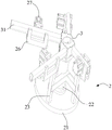
Fig. 1 is a schematic structural diagram of a robot rapid welding auxiliary fixture provided in embodiment 1;
fig. 2 is a schematic view of another angle structure of the robot rapid welding auxiliary clamp provided in embodiment 1;
FIG. 3 is a schematic structural view of a rotary platform provided in example 1;
FIG. 4 is a schematic structural view illustrating an operating state of the welding auxiliary clamp assembly according to embodiment 1;
in the above figures, 1, a rotary platform; 11. a base plate; 12. a support frame; 13. a rotating shaft; 14. a driven gear; 15. a rack; 16. a driving cylinder; 17. a connecting disc; 2. welding an auxiliary clamp assembly; 21. a turntable; 22. a main leg; 221. positioning a plate; 23. an auxiliary leg; 24. a workpiece substrate; 25. a fixing plate; 26. a clamping plate; 27. a clamping cylinder; 28. a connecting rod; 3. a welding part; 31. a pin.
Detailed Description
In order to make the above objects, features and advantages of the present invention more clearly understood, the present invention will be further described with reference to the accompanying drawings and examples. It should be noted that the embodiments and features of the embodiments of the present application may be combined with each other without conflict.
In the following description, numerous specific details are set forth in order to provide a thorough understanding of the present invention, however, the present invention may be practiced in other ways than those specifically described herein, and therefore the present invention is not limited to the limitations of the specific embodiments of the present disclosure.
Considering that the existing rotating platform is expensive, the present embodiment provides a rotating platform, and the rotating platform provided by the present embodiment includes a bottom plate and a supporting frame disposed above the bottom plate, in the present embodiment, the bottom plate mainly functions to fix and maintain the position of the whole auxiliary clamp, and for this reason, a bolt hole is disposed on the bottom plate for fixing on the ground or other platforms. The support frame is composed of two oppositely parallel vertical plates which are arranged in an inverted L shape, a channel for placing a cylinder, an electric push rod and an electric cylinder which are driven but not limited to is formed between the two vertical plates, bearing seats are arranged at the tops of the two vertical plates, rotating shafts are installed in the bearing seats, driven gears are sleeved on the rotating shafts, racks matched with the driven gears are arranged in the channel, and the racks and the rotating shafts are vertically arranged Under the effect of electric push rod, electric cylinder, realize the rack back-and-forth movement in the passageway, because driven gear and rack meshing, like this, at the effect of rack, driven gear takes place to rotate, simultaneously, is provided with the connection pad in the one end of pivot, and welding auxiliary fixture assembly passes through connection pad and rotary platform fixed connection, and then has realized the rotation of welding auxiliary fixture assembly.
Because the main parts of the rotary platform provided by the embodiment are the rack, the gear, and the cylinder, the electric push rod and the electric cylinder which comprise but are not limited to driving, the cost is far lower than that of the rotary platform used on the existing industrial robot, and the production cost is reduced.
In order to meet the requirement of auxiliary welding, the auxiliary welding fixture assembly provided in this embodiment includes a turntable connected to the rotating platform and a main leg disposed on the turntable, in this embodiment, the main leg and the turntable are disposed coaxially, that is, the main leg is disposed at a central position of the turntable, in this embodiment, the main leg mainly functions to place a main part to be welded, for this reason, a workpiece substrate is disposed at an end of the main leg away from the turntable, in this embodiment, a cross section of the welding part is disposed in a pentagonal shape, for this reason, the working substrate is also disposed in a pentagonal shape, a mounting hole is disposed on the working substrate for fixing the welding part, of course, the welding part can also be fixed in a clamping manner, such a fixing manner is mainly selected according to a product, in this embodiment, positioning discs are disposed at two ends of the main leg for different products, the main supporting leg is detachably and fixedly connected with the rotary table and the workpiece substrate through the positioning disc and the bolts, so that the main supporting leg structure and the shape of the working substrate can be selected at any time according to products, and the main supporting leg is arranged in a cuboid shape in the embodiment.
In order to fix and weld required pins conveniently, the turntable is further provided with auxiliary supporting legs, the auxiliary supporting legs are dispersedly arranged around the main supporting leg, in the embodiment, four auxiliary supporting legs are arranged, the four auxiliary supporting legs correspond to the four pins, the turntable is provided with mounting holes for fixing the auxiliary supporting legs through bolts, one ends of the auxiliary supporting legs, far away from the turntable, are provided with workpiece clamping mechanisms, and the workpiece clamping mechanisms mainly aim to clamp the pins so as to ensure the relative fixation between a welding part and the pins.
The clamping device comprises a fixing plate arranged on an auxiliary supporting leg and clamping plates arranged on two sides of the fixing plate, the fixing plate and the auxiliary supporting leg are fixed through bolts, the clamping plates and the fixing plate are also fixed through bolts, the fixing plate and the clamping plates are vertically arranged, one clamping plate is provided with a clamping cylinder, and a power end of the clamping cylinder penetrates through the clamping plates and extends into the space between the two clamping plates, so that pins can be firmly fixed by means of power of the clamping cylinder.
In order to ensure the stability of the main supporting leg and the auxiliary supporting leg, the supporting leg and the auxiliary supporting leg are further provided with connecting rods for radial connection, the connecting rods are fixed in a bolt fixing mode, and therefore the main supporting leg and the auxiliary supporting leg are integrated through connection of the connecting rods, and the fixing effect is improved.
The above description is only a preferred embodiment of the present invention, and is not intended to limit the present invention in other forms, and any person skilled in the art may use the above-mentioned technical contents to change or modify the equivalent embodiment into equivalent changes and apply to other fields, but any simple modification, equivalent change and modification made to the above embodiments according to the technical matters of the present invention will still fall within the protection scope of the technical solution of the present invention.
Claims (7)
1. The utility model provides a quick welding auxiliary fixture of robot, includes rotary platform and rotates the welding auxiliary fixture assembly that sets up on rotary platform, a serial communication port, welding auxiliary fixture assembly includes the carousel of being connected with rotary platform and sets up the main landing leg on the carousel, the perpendicular one side of keeping away from rotary platform at the carousel that sets up of main landing leg, still be provided with auxiliary leg on the carousel, auxiliary leg dispersion sets up all around of main landing leg, the one end that the carousel was kept away from to the main landing leg is provided with the work piece base plate, the one end that the carousel was kept away from to auxiliary leg is provided with work piece clamping mechanism, can dismantle fixed connection between main landing leg and carousel, the work piece base plate, can dismantle fixed connection between auxiliary leg and the work piece clamping mechanism.
2. The robot rapid welding auxiliary clamp of claim 1, wherein the rotating platform comprises a bottom plate and a support frame arranged above the bottom plate, a rotating shaft is arranged at the top of the support frame, a driven gear is sleeved on the rotating shaft, a rack matched with the driven gear is arranged on the support frame, a driving device for driving the rack to move back and forth is further arranged on the support frame, the rack and the rotating shaft are vertically arranged, a connecting disc is arranged at one end of the rotating shaft, and the welding auxiliary clamp assembly is fixedly connected with the rotating platform through the connecting disc.
3. The auxiliary fixture for robot rapid welding according to claim 2, wherein positioning discs are arranged at two ends of the main supporting leg, and the main supporting leg is detachably and fixedly connected with the turntable and the workpiece substrate through the positioning discs.
4. A robot rapid welding auxiliary fixture according to claim 3, characterized in that the workpiece clamping mechanism comprises a fixing plate arranged on the auxiliary supporting leg and clamping plates arranged on both sides of the fixing plate, wherein one of the clamping plates is provided with a clamping device.
5. A robot rapid welding auxiliary clamp according to claim 4, characterized in that a connecting rod for radial connection is further arranged between the main supporting leg and the auxiliary supporting leg.
6. A robot rapid welding auxiliary fixture according to claim 5, characterized in that the driving device is any one of a cylinder, an electric push rod or an electric cylinder.
7. The auxiliary robot clamp for rapid welding according to claim 5, wherein the clamping device is any one of a cylinder, an electric push rod or an electric cylinder, and the power end of the clamping device penetrates through the clamping plates and extends into the space between the two clamping plates.
Priority Applications (1)
| Application Number | Priority Date | Filing Date | Title |
|---|---|---|---|
| CN201921018460.1U CN210848930U (en) | 2019-07-02 | 2019-07-02 | Auxiliary clamp for rapid welding of robot |
Applications Claiming Priority (1)
| Application Number | Priority Date | Filing Date | Title |
|---|---|---|---|
| CN201921018460.1U CN210848930U (en) | 2019-07-02 | 2019-07-02 | Auxiliary clamp for rapid welding of robot |
Publications (1)
| Publication Number | Publication Date |
|---|---|
| CN210848930U true CN210848930U (en) | 2020-06-26 |
Family
ID=71295930
Family Applications (1)
| Application Number | Title | Priority Date | Filing Date |
|---|---|---|---|
| CN201921018460.1U Active CN210848930U (en) | 2019-07-02 | 2019-07-02 | Auxiliary clamp for rapid welding of robot |
Country Status (1)
| Country | Link |
|---|---|
| CN (1) | CN210848930U (en) |
Cited By (2)
| Publication number | Priority date | Publication date | Assignee | Title |
|---|---|---|---|---|
| CN112171019A (en) * | 2020-10-09 | 2021-01-05 | 曾宝香 | Automatic argon arc welding device |
| CN112643280A (en) * | 2021-02-22 | 2021-04-13 | 韦秋香 | Automatic fixing and clamping device for production and processing of low-voltage power distribution cabinet |
-
2019
- 2019-07-02 CN CN201921018460.1U patent/CN210848930U/en active Active
Cited By (2)
| Publication number | Priority date | Publication date | Assignee | Title |
|---|---|---|---|---|
| CN112171019A (en) * | 2020-10-09 | 2021-01-05 | 曾宝香 | Automatic argon arc welding device |
| CN112643280A (en) * | 2021-02-22 | 2021-04-13 | 韦秋香 | Automatic fixing and clamping device for production and processing of low-voltage power distribution cabinet |
Similar Documents
| Publication | Publication Date | Title |
|---|---|---|
| CN210848930U (en) | Auxiliary clamp for rapid welding of robot | |
| CN109623417A (en) | A kind of rotating machinery processing work platform | |
| CN212286745U (en) | Tool clamp for full-automatic machine manufacturing | |
| CN204565219U (en) | Couple yoke fabrication hole drilling tool | |
| CN214309860U (en) | Hardness detection device for material science | |
| CN110434514A (en) | It is a kind of can comprehensive adjusting welding robot and application method | |
| CN215588526U (en) | Quick positioning device for processing large parts on gantry milling machine | |
| CN214489342U (en) | Double-robot tower foot welding device | |
| CN113799013A (en) | Anchor clamps for mechanical maintenance | |
| CN210435652U (en) | Assembling device for manufacturing electric appliance | |
| CN210968566U (en) | Turnover mechanism for processing artware | |
| CN210524316U (en) | Many specifications cable support welding set | |
| CN108499458B (en) | Medical test tube mixing device with rotating frame | |
| CN209190470U (en) | A kind of leveling wire drawing all-in-one machine | |
| CN218137625U (en) | Tool jig for double-platform screw twisting machine | |
| CN215316719U (en) | 180-degree rotation self-balancing repair welding table | |
| CN108161855B (en) | Fixing device for robot joint reducer experiment table | |
| CN206869354U (en) | Rotate horizontally vehicle switching flexible welding workbench | |
| CN111331529A (en) | Bench clamp capable of fixing workpieces of multiple sizes | |
| CN210878374U (en) | Double-shaft H-shaped positioner | |
| CN215037204U (en) | Automobile cushion repairing wire station table | |
| CN220445524U (en) | Welding fixture | |
| CN219837392U (en) | Displacement machine for overturning large structural part | |
| CN219704714U (en) | Impact constant acceleration environment test fixture | |
| CN214518498U (en) | Valve body blade tooling table |
Legal Events
| Date | Code | Title | Description |
|---|---|---|---|
| GR01 | Patent grant | ||
| GR01 | Patent grant | ||
| CB03 | Change of inventor or designer information | ||
| CB03 | Change of inventor or designer information |
Inventor after: Wang Xianyong Inventor after: Liu Guanghui Inventor before: Wang Xianyong Inventor before: Wang Haibao Inventor before: Lin Ming |