CN210836526U - A power meter data collector - Google Patents
A power meter data collector Download PDFInfo
- Publication number
- CN210836526U CN210836526U CN201921955036.XU CN201921955036U CN210836526U CN 210836526 U CN210836526 U CN 210836526U CN 201921955036 U CN201921955036 U CN 201921955036U CN 210836526 U CN210836526 U CN 210836526U
- Authority
- CN
- China
- Prior art keywords
- data
- module
- power meter
- protocol conversion
- acquisition module
- Prior art date
- Legal status (The legal status is an assumption and is not a legal conclusion. Google has not performed a legal analysis and makes no representation as to the accuracy of the status listed.)
- Expired - Fee Related
Links
Images




Landscapes
- Arrangements For Transmission Of Measured Signals (AREA)
Abstract
本实用新型涉及一种电力电表数据汇集器,包括数据采集模块,所述数据采集模块的接收端与RFID模块相连,输出端与数据协议转换模块相连,所述数据协议转换模块还与串口通讯模块相连;其中,所述RFID模块通过无线自组网的方式与外部的环境传感器相连,用于接收外部的环境传感器发送的检测数据;所述数据协议转换模块用于将数据采集模块中的数据转换为符合电表国标协议的数据;所述串口通讯模块与电力电表数据接收机的485通信数据接收端口相连,用于将数据传输至电力电表数据接收机。本实用新型能够与现有电力电表数据接收机连接,实现无线采集。

The utility model relates to a power meter data collector, comprising a data acquisition module, a receiving end of the data acquisition module is connected with an RFID module, an output end is connected with a data protocol conversion module, and the data protocol conversion module is also connected with a serial port communication module Wherein, the RFID module is connected with the external environmental sensor by means of a wireless ad hoc network, and is used to receive the detection data sent by the external environmental sensor; the data protocol conversion module is used to convert the data in the data acquisition module. It is the data conforming to the national standard protocol of the electric meter; the serial communication module is connected with the 485 communication data receiving port of the electric energy meter data receiver, and is used for transmitting data to the electric energy meter data receiver. The utility model can be connected with the existing power meter data receiver to realize wireless collection.
Description
技术领域technical field
本实用新型涉及电力电表数据采集技术领域,特别是涉及一种电力电表数据汇集器。The utility model relates to the technical field of power meter data collection, in particular to a power meter data collector.
背景技术Background technique
电力电表数据采集接收机主要通过布置各种环境传感器来实现周围环境各项数据的收集。传统的电力电表数据采集接收机都是基于有线数据传输的形式集中收集数据,整个系统比较封闭,无法大容量的进行设备扩容。如现有公开专利CN202033890U,其公开了一种电力电表大用户远程集抄接口装置,该装置中的接收部件包括RS485通讯接收单元、光电隔离单元;所述RS485通讯接口单元用于读取电度表计量值。The power meter data acquisition receiver mainly realizes the collection of various data of the surrounding environment by arranging various environmental sensors. The traditional power meter data acquisition receiver is based on the centralized data collection in the form of wired data transmission. The whole system is relatively closed and cannot be expanded with large capacity. For example, the existing published patent CN202033890U discloses an interface device for remote centralized reading of electricity meters for large users. The receiving components in the device include an RS485 communication receiving unit and a photoelectric isolation unit; the RS485 communication interface unit is used to read electricity meter value.
由于RS485通讯接收单元是一种有线传输接收方式,因此其在接收数据时,需要对每个电力电表都进行相应的接线,因此其接线十分麻烦,并且对于系统的扩展也十分不方便。如果将现有的电力电表数据接收机全部改为无线接收方式,势必会对现有的装置全部更换,如此成本过高,因此亟需一种能够与现有电力电表数据接收机融合的无线采集装置。Since the RS485 communication receiving unit is a wired transmission and reception method, when it receives data, it needs to perform corresponding wiring for each power meter, so the wiring is very troublesome, and it is also very inconvenient for system expansion. If all the existing power meter data receivers are changed to wireless reception, all existing devices will be replaced, and the cost is too high. Therefore, there is an urgent need for a wireless acquisition that can be integrated with the existing power meter data receivers. device.
实用新型内容Utility model content
本实用新型所要解决的技术问题是提供一种电力电表数据汇集器,能够与现有电力电表数据接收机连接,实现无线采集。The technical problem to be solved by the utility model is to provide a power meter data collector, which can be connected with the existing power meter data receiver to realize wireless collection.
本实用新型解决其技术问题所采用的技术方案是:提供一种电力电表数据汇集器,包括数据采集模块,所述数据采集模块的接收端与RFID模块相连,输出端与数据协议转换模块相连,所述数据协议转换模块还与串口通讯模块相连;其中,所述RFID模块通过无线自组网的方式与外部的环境传感器相连,用于接收外部的环境传感器发送的检测数据;所述数据协议转换模块用于将数据采集模块中的数据转换为符合电表国标协议的数据;所述串口通讯模块与电力电表数据接收机的485通信数据接收端口相连,用于将数据传输至电力电表数据接收机。The technical solution adopted by the utility model to solve the technical problem is: to provide a power meter data collector, comprising a data acquisition module, the receiving end of the data acquisition module is connected with the RFID module, and the output end is connected with the data protocol conversion module, The data protocol conversion module is also connected with the serial communication module; wherein, the RFID module is connected with an external environmental sensor through a wireless ad hoc network, and is used for receiving detection data sent by the external environmental sensor; the data protocol conversion The module is used to convert the data in the data acquisition module into data conforming to the national standard protocol of the electricity meter; the serial communication module is connected to the 485 communication data receiving port of the electricity meter data receiver for transmitting data to the electricity meter data receiver.
所述数据采集模块采用的芯片为M16C64。The chip used in the data acquisition module is M16C64.
所述RFID模块采用的RFID芯片为AT86RF233、NRF8001、MKW41Z512、 MCR20AVHM、或nRF24L01+。The RFID chip used in the RFID module is AT86RF233, NRF8001, MKW41Z512, MCR20AVHM, or nRF24L01+.
所述数据协议转换模块为DL/T645-2007数据协议转换模块。The data protocol conversion module is a DL/T645-2007 data protocol conversion module.
所述串口通讯模块采用的485芯片为MAX3485EE或SPX3485。The 485 chip used in the serial communication module is MAX3485EE or SPX3485.
所述数据采集模块还连接有JTAG下载模块,所述JTAG下载模块用于对数据采集模块进行调试,其采用的芯片为SAMR21G18。The data acquisition module is also connected with a JTAG download module, and the JTAG download module is used to debug the data acquisition module, and the chip used is SAMR21G18.
所述数据采集模块还连接有LED指示模块,所述LED指示模块用于显示所述电力电表数据汇集器的工作状态。The data acquisition module is also connected with an LED indication module, and the LED indication module is used to display the working state of the power meter data collector.
有益效果beneficial effect
由于采用了上述的技术方案,本实用新型与现有技术相比,具有以下的优点和积极效果:本实用新型通过RFID模块实现数据的无线采集,并通过数据协议转换模块将采集到的无线数据转换为能够进行有线传输电表国标协议的数据,并通过串口通讯模块与现有的电力电表数据接收机连接,使得现有电力电表数据接收机在与本实用新型的装置连接后能够实现无线采集。Compared with the prior art, the present utility model has the following advantages and positive effects due to the adoption of the above-mentioned technical solutions: the present utility model realizes the wireless data collection through the RFID module, and converts the collected wireless data through the data protocol conversion module. It is converted into data that can transmit the data of the national standard protocol of the electric meter, and is connected with the existing electric power meter data receiver through the serial communication module, so that the existing electric power meter data receiver can realize wireless collection after being connected with the device of the utility model.
附图说明Description of drawings
图1是本实用新型的结构方框图;Fig. 1 is the structural block diagram of the present utility model;
图2是本实用新型中一种数据采集模块的电路图;Fig. 2 is the circuit diagram of a kind of data acquisition module in the utility model;
图3是本实用新型中一种RFID模块的电路图;Fig. 3 is the circuit diagram of a kind of RFID module in the utility model;
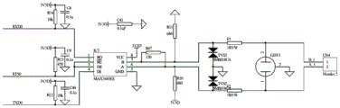
图4是本实用新型中一种串口通讯模块的电路图;Fig. 4 is the circuit diagram of a kind of serial communication module in the utility model;
图5是本实用新型中一种JTAG下载模块的电路图;Fig. 5 is the circuit diagram of a kind of JTAG download module in the utility model;
图6是本实用新型中一种LED指示模块的电路图。FIG. 6 is a circuit diagram of an LED indicating module in the present invention.
具体实施方式Detailed ways
下面结合具体实施例,进一步阐述本实用新型。应理解,这些实施例仅用于说明本实用新型而不用于限制本实用新型的范围。此外应理解,在阅读了本实用新型讲授的内容之后,本领域技术人员可以对本实用新型作各种改动或修改,这些等价形式同样落于本申请所附权利要求书所限定的范围。The present utility model will be further described below in conjunction with specific embodiments. It should be understood that these embodiments are only used to illustrate the present invention and not to limit the scope of the present invention. In addition, it should be understood that after reading the content taught by the present invention, those skilled in the art can make various changes or modifications to the present invention, and these equivalent forms also fall within the scope defined by the appended claims of the present application.
本实用新型的实施方式涉及一种电力电表数据汇集器,如图1所示,包括数据采集模块,所述数据采集模块的接收端与RFID模块相连,输出端与数据协议转换模块相连,所述数据协议转换模块还与串口通讯模块相连;其中,所述RFID模块通过无线自组网的方式与外部的环境传感器相连,用于接收外部的环境传感器发送的检测数据;所述数据协议转换模块用于将数据采集模块中的数据转换为符合电表国标协议的数据;所述串口通讯模块与电力电表数据接收机的485通信数据接收端口相连,用于将数据传输至电力电表数据接收机。The embodiment of the present utility model relates to a power meter data collector, as shown in FIG. 1 , including a data acquisition module, the receiving end of the data acquisition module is connected with the RFID module, and the output end is connected with the data protocol conversion module. The data protocol conversion module is also connected with the serial communication module; wherein, the RFID module is connected with an external environmental sensor by means of a wireless ad hoc network, and is used for receiving detection data sent by the external environmental sensor; the data protocol conversion module is used for It is used to convert the data in the data acquisition module into data conforming to the national standard protocol of the electricity meter; the serial communication module is connected to the 485 communication data receiving port of the electricity meter data receiver, and is used to transmit the data to the electricity meter data receiver.
由此可见,本实用新型通过RFID模块实现数据的无线采集,并通过数据协议转换模块将采集到的无线数据转换为能够进行有线传输的电表国标协议的数据,并通过串口通讯模块与现有的电力电表数据接收机连接,使得现有电力电表数据接收机在与本实用新型的装置连接后能够实现无线采集。通过本实用新型的电力电表数据汇集器可以与现有的电力电表数据接收机直接连接,无需对现有的电力电表数据接收机进行更换,降低了成本。It can be seen that the utility model realizes the wireless collection of data through the RFID module, and converts the collected wireless data into the data of the national standard protocol of the electric meter that can be transmitted by wire through the data protocol conversion module, and communicates with the existing data through the serial port communication module. The power meter data receiver is connected, so that the existing power meter data receiver can realize wireless collection after being connected with the device of the utility model. The power meter data collector of the utility model can be directly connected with the existing power meter data receiver, and the existing power meter data receiver does not need to be replaced, thereby reducing the cost.
如图2所示,本实施方式中的数据采集模块可以采用的芯片为M16C64,该芯片具有低功耗、高性能、高处理速度、接口丰富、内存资源大、高可靠性、工业级的工作温度-40℃~85℃的特点。As shown in FIG. 2 , the chip that can be used by the data acquisition module in this embodiment is M16C64, which has low power consumption, high performance, high processing speed, rich interfaces, large memory resources, high reliability, and industrial-grade work. Temperature -40 ℃ ~ 85 ℃ characteristics.
本实施方式中的RFID模块采用的RFID芯片为AT86RF233、NRF8001、MKW41Z512、MCR20AVHM、或nRF24L01+。图3所示的是AT86RF233芯片的电路图。该AT86RF233 芯片是富有特性极低功耗的单片2.4GHz无线收发器,其接收器灵敏度为-101dBm,可编程输出功率从-17dBm到+40dBm,工作电压为1.8V-3.6V,深度睡眠功耗为0.02uA。由于该芯片的低功耗,可以实现内置锂电池提供长达10年以上的使用寿命。The RFID chip used by the RFID module in this embodiment is AT86RF233, NRF8001, MKW41Z512, MCR20AVHM, or nRF24L01+. Figure 3 shows the circuit diagram of the AT86RF233 chip. The AT86RF233 chip is a monolithic 2.4GHz wireless transceiver with very low power consumption. Its receiver sensitivity is -101dBm, its programmable output power is from -17dBm to +40dBm, its working voltage is 1.8V-3.6V, and its deep sleep function is The consumption is 0.02uA. Due to the low power consumption of the chip, the built-in lithium battery can provide a service life of more than 10 years.
本实施方式中的串口通讯模块采用的485芯片为MAX3485EE或SPX3485,图4所示的是MAX3485EE芯片的电路图。本实施方式中的串口通讯模块与现有电力电表数据接收机的485通信数据接收端口所用的模块相同,在此不再赘述。The 485 chip used by the serial communication module in this embodiment is MAX3485EE or SPX3485, and FIG. 4 shows the circuit diagram of the MAX3485EE chip. The serial communication module in this embodiment is the same as the module used by the 485 communication data receiving port of the existing power meter data receiver, and details are not described here.
本实施方式中的数据协议转换模块为DL/T645-2007数据协议转换模块,该协议转换模块可以将无线传输协议的数据转换为符合电表国标DL/T645-2007的数据。The data protocol conversion module in this embodiment is a DL/T645-2007 data protocol conversion module, and the protocol conversion module can convert the data of the wireless transmission protocol into data conforming to the national standard for electricity meters DL/T645-2007.
所述数据采集模块还连接有JTAG下载模块,所述JTAG下载模块用于对数据采集模块进行调试,其采用的芯片为SAMR21G18。图5所示的是该JTAG下载模块电路图。The data acquisition module is also connected with a JTAG download module, and the JTAG download module is used to debug the data acquisition module, and the chip used is SAMR21G18. Figure 5 shows the circuit diagram of the JTAG download module.
所述数据采集模块还连接有LED指示模块,所述LED指示模块用于显示所述电力电表数据汇集器的工作状态。图6所示的是该LED指示模块的电路图,其共有三个LED,分别通过PA05、PA06和PA07与控制单元的三个I/O端相连,以使控制单元能够在不同工作状态下选通不同的LED。该LED指示模块能够在不同的工作状态下显示不同颜色的LED 指示灯,例如在RFID模块进行数据接收时,可以显示红色的LED指示灯,在串口通讯模块进行数据传输时,可以显示绿色的LED指示灯。通过显示不同颜色的LED指示灯能够清楚的知道整个电力电表数据汇集器的工作状态,方便工作人员观察。The data acquisition module is also connected with an LED indication module, and the LED indication module is used to display the working state of the power meter data collector. Figure 6 shows the circuit diagram of the LED indicating module. There are three LEDs in total, which are connected to the three I/O terminals of the control unit through PA05, PA06 and PA07, respectively, so that the control unit can be gated in different working states. different LEDs. The LED indicator module can display LED indicators of different colors in different working states. For example, when the RFID module is receiving data, it can display a red LED indicator, and when the serial communication module is performing data transmission, it can display a green LED. indicator light. By displaying LED indicators of different colors, the working status of the entire power meter data collector can be clearly known, which is convenient for staff to observe.
该电力电表数据采集汇集器的工作流程如下:RFID模块实时接收来自外部环境传感器传输的检测数据,数据采集模块对检测到的数据进行采集,并通过数据协议模块将检测到的无线数据的协议转换为符合电表国标DL/T645-2007的数据,串口通讯模块则将协议转换后的数据上传至现有的电力电表数据接收机,如此可以使得在不更换现有电力电表数据接收机的基础上实现无线采集。The work flow of the power meter data collection and collector is as follows: the RFID module receives the detection data transmitted from the external environmental sensor in real time, the data collection module collects the detected data, and converts the detected wireless data to the protocol through the data protocol module In order to comply with the data of the national standard of electricity meter DL/T645-2007, the serial communication module uploads the data converted by the protocol to the existing electricity meter data receiver, so that it can be realized without replacing the existing electricity meter data receiver. Wireless collection.
Claims (7)
Priority Applications (1)
| Application Number | Priority Date | Filing Date | Title |
|---|---|---|---|
| CN201921955036.XU CN210836526U (en) | 2019-11-13 | 2019-11-13 | A power meter data collector |
Applications Claiming Priority (1)
| Application Number | Priority Date | Filing Date | Title |
|---|---|---|---|
| CN201921955036.XU CN210836526U (en) | 2019-11-13 | 2019-11-13 | A power meter data collector |
Publications (1)
| Publication Number | Publication Date |
|---|---|
| CN210836526U true CN210836526U (en) | 2020-06-23 |
Family
ID=71252768
Family Applications (1)
| Application Number | Title | Priority Date | Filing Date |
|---|---|---|---|
| CN201921955036.XU Expired - Fee Related CN210836526U (en) | 2019-11-13 | 2019-11-13 | A power meter data collector |
Country Status (1)
| Country | Link |
|---|---|
| CN (1) | CN210836526U (en) |
-
2019
- 2019-11-13 CN CN201921955036.XU patent/CN210836526U/en not_active Expired - Fee Related
Similar Documents
| Publication | Publication Date | Title |
|---|---|---|
| CN103986416B (en) | A kind of portable light photovoltaic assembly monitoring side | |
| CN208903415U (en) | A kind of 230MHz LoRa collector meeting southern network mark standard | |
| CN201789339U (en) | Substation operation data monitoring and alarm system | |
| CN205142280U (en) | Data acquisition system | |
| CN102722167A (en) | Integrated controller for floor | |
| CN204758062U (en) | Intelligent teletransmission gas of thing networking table | |
| CN107786165A (en) | A kind of photovoltaic battery array performance monitoring system based on ZigBee | |
| CN212256564U (en) | Internet of things metering instrument universal system for electric signal output type instrument | |
| CN201396150Y (en) | Integrative digital wireless thermoscope | |
| CN207037899U (en) | A kind of Multi-meter collecting equipment | |
| CN201936016U (en) | Landslide monitoring device | |
| CN108710333A (en) | A kind of water quality monitoring system based on ZigBee | |
| CN205642431U (en) | Power equipment parameter detecting system based on wireless sensor network | |
| CN106655492A (en) | Smart power grid line safety real-time monitoring device | |
| CN102506932A (en) | Thermodynamic type energy-efficiency data acquisition terminal | |
| CN203630377U (en) | Weather station of unibus structure | |
| CN203365669U (en) | Running state on-line monitoring device for electronic mutual inductor | |
| CN212259017U (en) | General system of Internet of things metering instrument for pointer instrument | |
| CN211180611U (en) | A battery-powered NB-MBUS collector | |
| CN206991536U (en) | SCM Based long-distance meter-reading system | |
| CN208013129U (en) | A kind of intelligent ozone sensor | |
| CN210721829U (en) | Electric power ammeter data acquisition receiver | |
| CN211783600U (en) | A hydropower station environmental monitoring system | |
| CN206649653U (en) | A kind of wind field data collecting system | |
| CN209842859U (en) | Wireless communication handset and remote meter reading system based on LoRa |
Legal Events
| Date | Code | Title | Description |
|---|---|---|---|
| GR01 | Patent grant | ||
| GR01 | Patent grant | ||
| CF01 | Termination of patent right due to non-payment of annual fee | ||
| CF01 | Termination of patent right due to non-payment of annual fee |
Granted publication date: 20200623 |