CN210817590U - Efficient turbine oil guide plate drilling tool - Google Patents
Efficient turbine oil guide plate drilling tool Download PDFInfo
- Publication number
- CN210817590U CN210817590U CN201921179738.3U CN201921179738U CN210817590U CN 210817590 U CN210817590 U CN 210817590U CN 201921179738 U CN201921179738 U CN 201921179738U CN 210817590 U CN210817590 U CN 210817590U
- Authority
- CN
- China
- Prior art keywords
- plate
- drill
- oil guide
- drilling tool
- drilling
- Prior art date
- Legal status (The legal status is an assumption and is not a legal conclusion. Google has not performed a legal analysis and makes no representation as to the accuracy of the status listed.)
- Active
Links
Images


Landscapes
- Drilling And Boring (AREA)
Abstract
The utility model discloses an efficient turbine leads oiled-plate drilling frock, which comprises a pressing plate and i, clamp plate trompil and lead screw trompil have been seted up to the clamp plate upper surface, and the clamp plate lower surface is connected with the jig body, jig body upper surface is provided with the drill bushing, and jig body lower surface is connected with leads the oiled-plate, it is connected with jig base subassembly to lead the oiled-plate lower surface, the lead screw trompil runs through there is the lead screw, the nut has been cup jointed to the upper and lower end of lead screw. The drill bushing is arranged on the upper surface of the drill jig body, and when the oil guide plate needs to be drilled, only drilling equipment needs to penetrate into the drill bushing to drill, so that the design omits a scribing process before drilling, the time of the whole process is greatly shortened, the labor cost is reduced, and meanwhile, the drilling quality is improved and ensured; through leading the oiled-plate setting between brill die body and first disc, the quantity that the turbine of drilling frock can once bore the turbine leads the oiled-plate is 15, when not using the frock, efficiency improvement 15 times.
Description
Technical Field
The utility model relates to an oil board drilling technical field is led to hydraulic coupling turbine, specifically is an oil board drilling frock is led to efficient turbine.
Background
The tool is a device for fixing parts to be machined, so that the parts can be accurately machined, and particularly in the drilling of workpieces, the poor stability of the workpieces can cause the low quality and efficiency of the drilling, and defective products are easy to generate. The existing workpiece drilling tool is mostly of a structure customized for a certain workpiece, is poor in universality and small in application range, and also improves the cost for manufacturing a plurality of tools.
However, the drilling tool has the defects of low stability, small application range and high operation cost of the workpiece in the drilling process. Therefore, the technical personnel in the field provide an efficient turbine oil guide plate drilling tool to solve the problems in the background art.
SUMMERY OF THE UTILITY MODEL
An object of the utility model is to provide an efficient turbine oil guide plate drilling frock to solve the problem that proposes among the above-mentioned background art.
In order to achieve the above object, the utility model provides a following technical scheme:
the utility model provides an efficient turbine leads oil board drilling frock, includes the clamp plate, clamp plate trompil and lead screw trompil have been seted up to the clamp plate upper surface, and the clamp plate lower surface is connected with the jig body, jig body upper surface is provided with the drill bushing, and jig body lower surface is connected with leads the oil board, it is connected with jig base subassembly to lead oil board lower surface, the lead screw trompil runs through there is the lead screw, the nut has been cup jointed to the upper and lower end of lead screw.
As a further aspect of the present invention: the drill jig base assembly comprises a circular plate, a second circular plate, a rib plate, a first circular plate and a circular cylinder, wherein the circular plate is fixed on the lower surface of the circular cylinder, the rib plate is fixed on the outer surface of the circular cylinder, the upper surface of the rib plate is connected with the first circular plate, and the lower surface of the rib plate is connected with the second circular plate.
As a further aspect of the present invention: the circular plate, the second circular plate, the rib plate, the first circular plate and the cylinder are all made of Q235-A materials.
As a further aspect of the present invention: the number of the press plate openings is four, and the press plate openings are symmetrically arranged on the upper surface of the press plate in pairs.
As a further aspect of the present invention: the screw rod and the nut are members made of the same material.
As a further aspect of the present invention: the number of the drill bushings is sixteen, and the drill bushings are evenly distributed along the upper surface of the drill jig body.
As a further aspect of the present invention: the number of the rib plates is eight, and the rib plates are symmetrically arranged between the first disc and the second disc in pairs.
As a further aspect of the present invention: the diameter of the pressure plate is smaller than the inner diameter of a circle surrounded by the drill bushing.
Compared with the prior art, the beneficial effects of the utility model are that:
1. through setting up the drill bushing at the jig body upper surface, when needs are drilled the oil guide plate, only need with drilling equipment penetrate the drill bushing drill hole can, the line marking process before drilling has been saved in this design, has shortened the time of whole process greatly, has reduced the cost of labor, simultaneously, improves and has guaranteed drilling quality.
2. Through leading the oiled-plate setting between brill die body and first disc, the quantity that the turbine of drilling frock can once bore the turbine leads the oiled-plate is 15, when not using the frock, efficiency improvement 15 times.
3. The drilling tool can be suitable for drilling 3 turbine oil baffle plates in hydraulic coupler models YOTCGP800, 875 and 920, increases the practicability of the drilling tool, and is easy to push to the market.
Drawings
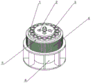
FIG. 1 is a schematic structural view of an efficient turbine oil deflector drilling tool;
FIG. 2 is a cross-sectional view of an efficient turbine oil deflector drilling tool;
fig. 3 is a schematic structural diagram of a drill jig base assembly of an efficient turbine oil guide plate drilling tool.
In the figure: 1. drilling a sleeve; 2. punching holes on the pressing plate; 3. pressing a plate; 4. an oil guide plate; 5. drilling a mould body; 6. a drill jig base assembly; 7. a nut; 8. a screw rod; 9. a circular plate; 10. a second disc; 11. a rib plate; 12. a first disc; 13. a cylinder; 14. and (6) tapping the screw rod.
Detailed Description
Please refer to fig. 1-3, in the embodiment of the present invention, an efficient turbine oil guide plate drilling tool, including the clamp plate 3, clamp plate trompil 2 and lead screw trompil 14 have been seted up to the clamp plate 3 upper surface, and the clamp plate 3 lower surface is connected with the drill jig body 5, the diameter of clamp plate 3 is less than the internal diameter that drill bushing 1 encloses into the circle, clamp plate trompil 2 quantity is four, and clamp plate trompil 2 is two liang of symmetrical arrangement at the clamp plate 3 upper surface, the drill jig body 5 upper surface is provided with drill bushing 1, and drill jig body 5 lower surface is connected with oil guide plate 4, this design, through with oil guide plate 4 setting between drill jig body 5 and first disc 12, the quantity that the drilling tool can once bore turbine oil guide plate is 15, when not using the tool, efficiency improves 15 times.
In fig. 1: the quantity of drill bushing 1 is sixteen, and drill bushing 1 is along 5 upper surface evenly distributed of jig body, it is connected with jig base subassembly 6 to lead 4 lower surfaces of oilplate, this design, through set up drill bushing 1 on jig body upper surface, when needs are drilled oil plate 4, only need with drilling equipment penetrate drill bushing 1 and drill can, the line marking process before drilling has been saved in this design, the time of whole process has been shortened greatly, the labor cost is reduced, and simultaneously, the drilling quality is improved and guaranteed.
In fig. 1, 3: the drill jig base assembly 6 comprises a circular plate 9, a second circular plate 10, a rib plate 11, a first circular plate 12 and a cylinder 13, wherein the circular plate 9 is fixed on the lower surface of the cylinder 13, the outer surface of the cylinder 13 is fixedly provided with rib plates 11, the number of the rib plates 11 is eight, the rib plates 11 are symmetrically arranged between the first disk 12 and the second disk 10 in pairs, the disk 9, the second disk 10, the rib plates 11, the first disk 12 and the cylinder 13 are all made of Q235-A materials, the upper surface of the rib plate 11 is connected with the first disk 12, and 11 lower surfaces of gusset are connected with second disc 10, lead screw trompil 14 runs through there is lead screw 8, nut 7 has been cup jointed to the upper and lower end of lead screw 8, lead screw 8 and nut 7 are the same component of material, this drilling frock is applicable to the drilling of 3 kinds of turbine oil guide plates 4 in fluid coupling type number YOTCGP800, 875, 920 three kinds of models, has increased the practicality of this drilling frock, easily pushes to market.
The utility model discloses a theory of operation is: firstly, taking out the drill jig base assembly 6, transversely placing the drill jig base assembly on a table top, then holding the drill jig base assembly by one hand, then taking out the screw rod 8, screwing one end with less threads of the screw rod 8 into one nut 7 until the end is screwed to three quarters of the threads, then inserting one end of the screw rod 8, which is screwed with the nut 7, into an opening in the center of the circular plate 9, screwing the other nut 7 into the screw rod 8 at the other end of the circular plate 9, fixing the screw rod 8 at the center of the circular plate 9 by the two nuts 7, then flatly placing the drill jig base assembly 6 on the table top, then placing the oil guide plate 4 on the first disc 12, placing the drill jig body 5 on the oil guide plate 4, aligning the press plate opening 2 with the screw rod 8, placing the press plate 3 on the upper surface of the drill jig body 5, taking out the nut 7, screwing the top end of the screw rod 8 by the nut 7, and enabling components between the press plate 3 and the drill jig base assembly 6 not to randomly, at the moment, the efficient drilling tool for the turbine oil guide plate 4 is assembled, when the tool works, drilling equipment is used for drilling holes in the position of the oil guide plate 4 along a drill bushing, due to the fact that the drill bushing 1 is arranged, the marking process before drilling is omitted, the time of the whole process is greatly shortened, the labor cost is reduced, meanwhile, the drilling quality is improved and guaranteed, due to the design, 15 layers of oil guide plates 4 can be drilled together at most once, the working efficiency is improved by 15 times, after the drilling is finished, the drilling equipment is firstly removed, then the nut 7 at the top end is unscrewed through a wrench, the pressing plate 3 is removed, after the pressing plate 3 is removed, the drill die body 5 is also removed, then the oil guide plates 4 can be taken out, the next batch of oil guide plates 4 are placed on the first disc 12, and the oil guide plates 4 are continuously drilled.
The above-mentioned, only be the concrete implementation of the preferred embodiment of the present invention, but the protection scope of the present invention is not limited thereto, and any person skilled in the art is in the technical scope of the present invention, according to the technical solution of the present invention and the utility model, the concept of which is equivalent to replace or change, should be covered within the protection scope of the present invention.
Claims (8)
1. The utility model provides an efficient turbine leads oil board drilling frock, includes clamp plate (3), its characterized in that, clamp plate trompil (2) and lead screw trompil (14) have been seted up to clamp plate (3) upper surface, and clamp plate (3) lower surface is connected with drill jig body (5), drill jig body (5) upper surface is provided with drill bushing (1), and drill jig body (5) lower surface is connected with leads oil board (4), it is connected with drill jig base subassembly (6) to lead oil board (4) lower surface, lead screw trompil (14) run through lead screw (8), nut (7) have been cup jointed to the end about lead screw (8).
2. The efficient turbine oil guide plate drilling tool according to claim 1, wherein the drill jig base assembly (6) comprises a circular plate (9), a second circular plate (10), a rib plate (11), a first circular plate (12) and a circular cylinder (13), the circular plate (9) is fixed to the lower surface of the circular cylinder (13), the rib plate (11) is fixed to the outer surface of the circular cylinder (13), the first circular plate (12) is connected to the upper surface of the rib plate (11), and the second circular plate (10) is connected to the lower surface of the rib plate (11).
3. The efficient turbine oil guide plate drilling tool according to claim 2, wherein the circular plate (9), the second circular plate (10), the rib plate (11), the first circular plate (12) and the cylinder (13) are all made of Q235-A materials.
4. The efficient turbine oil guide plate drilling tool is characterized in that the number of the pressure plate openings (2) is four, and the pressure plate openings (2) are symmetrically arranged on the upper surface of the pressure plate (3) in pairs.
5. The efficient turbine oil guide plate drilling tool according to claim 1, wherein the screw rod (8) and the nut (7) are components made of the same material.
6. The efficient turbine oil guide plate drilling tool is characterized in that the number of the drill bushings (1) is sixteen, and the drill bushings (1) are uniformly distributed along the upper surface of a drill die body (5).
7. The efficient turbine oil guide plate drilling tool according to claim 2, wherein the number of the rib plates (11) is eight, and the rib plates (11) are symmetrically arranged between the first disc (12) and the second disc (10) in pairs.
8. The efficient turbine oil guide plate drilling tool is characterized in that the diameter of the pressure plate (3) is smaller than the inner diameter of a circle surrounded by the drill bushing (1).
Priority Applications (1)
| Application Number | Priority Date | Filing Date | Title |
|---|---|---|---|
| CN201921179738.3U CN210817590U (en) | 2019-07-25 | 2019-07-25 | Efficient turbine oil guide plate drilling tool |
Applications Claiming Priority (1)
| Application Number | Priority Date | Filing Date | Title |
|---|---|---|---|
| CN201921179738.3U CN210817590U (en) | 2019-07-25 | 2019-07-25 | Efficient turbine oil guide plate drilling tool |
Publications (1)
| Publication Number | Publication Date |
|---|---|
| CN210817590U true CN210817590U (en) | 2020-06-23 |
Family
ID=71276057
Family Applications (1)
| Application Number | Title | Priority Date | Filing Date |
|---|---|---|---|
| CN201921179738.3U Active CN210817590U (en) | 2019-07-25 | 2019-07-25 | Efficient turbine oil guide plate drilling tool |
Country Status (1)
| Country | Link |
|---|---|
| CN (1) | CN210817590U (en) |
Cited By (1)
| Publication number | Priority date | Publication date | Assignee | Title |
|---|---|---|---|---|
| CN115194484A (en) * | 2022-08-04 | 2022-10-18 | 山东省章丘鼓风机股份有限公司 | Pump case end face machining device and machining method |
-
2019
- 2019-07-25 CN CN201921179738.3U patent/CN210817590U/en active Active
Cited By (1)
| Publication number | Priority date | Publication date | Assignee | Title |
|---|---|---|---|---|
| CN115194484A (en) * | 2022-08-04 | 2022-10-18 | 山东省章丘鼓风机股份有限公司 | Pump case end face machining device and machining method |
Similar Documents
| Publication | Publication Date | Title |
|---|---|---|
| CN204053021U (en) | A kind of round-disk shape workpiece Quick drilling tool | |
| CN203556902U (en) | Hydraulic self-centering pull-down expansion sleeve mechanism | |
| CN104959864A (en) | Numerical control machine tool clamp | |
| CN104924125A (en) | Universal clamp for numerical control machine tool | |
| CN103949909A (en) | CNC (computer numerical control) machined spherical piece combined clamp and clamping method | |
| CN204248561U (en) | A kind of multi-functional mobile drill clamp for shaft coupling | |
| CN104924111A (en) | Automatic clamp for numerical control machine tool | |
| CN203292523U (en) | Oil pump body coaxial size machining tool | |
| CN210817590U (en) | Efficient turbine oil guide plate drilling tool | |
| CN203993245U (en) | The quick positioning drill jig of wind tower flange | |
| CN109676421B (en) | Special fixture for high-precision spherical hole drilling on rocker arm part | |
| CN206286870U (en) | A kind of helical pitch cylinder bores array hole fixture | |
| CN209811753U (en) | Four-axis machining center frock quick change anchor clamps | |
| CN219522344U (en) | Processing equipment for counter bore of silicon rubber plate | |
| CN212310928U (en) | Inclined hole drilling device | |
| CN209754641U (en) | special fixture for drilling high-precision spherical hole on swinging arm piece | |
| CN211708180U (en) | Clamping tool for drilling retainer | |
| CN203636145U (en) | Wire cutting machine clamp for aluminum alloy extrusion die processing | |
| CN210209529U (en) | Universal positioning and clamping system | |
| CN206509776U (en) | A kind of integrated quick change clamping device of long crack waveguide tube end machining multistation | |
| CN203437963U (en) | Main machine barrel inner bore boring tool | |
| CN220073944U (en) | Vertical machining device for speed reducer cover | |
| CN206405471U (en) | A kind of steel construction spike body end plate drilling device | |
| CN104816180A (en) | Power takeoff box drilling fixture | |
| CN204818809U (en) | Boring grab |
Legal Events
| Date | Code | Title | Description |
|---|---|---|---|
| GR01 | Patent grant | ||
| GR01 | Patent grant |