CN210766855U - Multi-barrel combined foundation system connected with offshore wind power box-shaped beams - Google Patents
Multi-barrel combined foundation system connected with offshore wind power box-shaped beams Download PDFInfo
- Publication number
- CN210766855U CN210766855U CN201921370153.XU CN201921370153U CN210766855U CN 210766855 U CN210766855 U CN 210766855U CN 201921370153 U CN201921370153 U CN 201921370153U CN 210766855 U CN210766855 U CN 210766855U
- Authority
- CN
- China
- Prior art keywords
- barrel
- box
- transition section
- girder
- negative pressure
- Prior art date
- Legal status (The legal status is an assumption and is not a legal conclusion. Google has not performed a legal analysis and makes no representation as to the accuracy of the status listed.)
- Active
Links
Images


Abstract
The utility model discloses a many buckets of combination foundation system that offshore wind-power box type roof beam is connected, its structure includes that negative pressure suction bucket, changeover portion center section of thick bamboo and box are even roof beam, and changeover portion center section of thick bamboo outside circumference equidistance sets up a plurality of boxes and even roof beam, every box is even the below of roof beam and is set up a negative pressure suction bucket. The utility model discloses to different depth of water condition and seabed characteristic in the complicated sea area of china to negative pressure suction bucket tripod basis is basic design pattern, links the roof beam through the box and connects negative pressure suction bucket and major diameter single pile basis, draws the anchor system to improve the holistic rigidity and the bearing capacity on basis through increasing the prestressing force, under the prerequisite of guaranteeing the engineering design requirement, provides a construction convenience and low economic's basic system, can be applicable to multiple depth of water and seabed condition.
Description
Technical Field
The utility model belongs to the technical field of relevant with ocean geotechnical engineering, at marine aerogenerator basic design, relate to a many buckets of combination foundation systems that offshore wind power box girder was connected in complicated sea area condition, to the complicated sea area condition of china's coastal waters, provide one set of marine wind power composite foundation system who is suitable for multiple depth of water and seabed condition.
Background
Under the large background that global environmental and energy problems are increasingly prominent, new renewable energy sources are favored by countries in the world. Compared with expensive solar power generation and nearly saturated hydropower resources, offshore wind power generation has the advantages of abundant resource reserves, stable power generation, convenient power grid access and the like, so that rapid development is achieved in recent years. By 2018, europe has installed grid-tied 18.5GW offshore wind power, including 4543 wind generators distributed in 11 countries. Compared with Europe, offshore wind power in China starts late, but under the strong promotion of government subsidies and national policies, rapid development is achieved in recent years, and the market prospect is wide. At present, offshore wind power in China basically has large-scale development conditions, and the next stage needs technical innovation and large-scale development, so that the construction cost is reduced, subsidy dependence is eliminated as soon as possible, and rapid development is realized.
However, compared with the uniform dense sandy soil seabed in Europe, offshore wind power construction sea area conditions in China are complex, and the variability of water depth and seabed conditions is large, so that more challenges are provided for the basic design of offshore wind power: in offshore areas of Fujian and Liaoning in China, seabed bedrock is buried shallowly, and the traditional wind power pile foundation needs offshore rock embedding construction, so that the construction period is long, the risk is high, and the manufacturing cost is high; in the offshore area of Zhejiang, the seabed sludge layer is deep, the soil body bearing capacity is low, and the applicability of the offshore large-diameter single-pile foundation is poor; in the offshore area of Guangdong, the water depth is deep, the wave is large, the tide is rapid, and the deformation of the foundation water entering section under extreme load is very obvious. In addition, the offshore wind power base cost can account for about 30% of the investment of the whole project due to the harsh offshore construction conditions. Therefore, the novel, cheap, convenient and reliable offshore wind turbine foundation system which is suitable for the complex sea area of China is provided, and has important engineering and economic significance for offshore wind turbine construction of China.
SUMMERY OF THE UTILITY MODEL
The utility model discloses to different depth of water conditions and seabed characteristic in the complicated sea area of china, aim at providing the many buckets combination foundation system that a marine wind-power box type roof beam is connected that multiple depth of water and seabed condition in the adaptation complicated sea area condition.
In order to achieve the above purpose, the utility model adopts the following technical scheme:
the utility model discloses a many buckets of combination foundation system that offshore wind-power box type roof beam is connected, link the roof beam including negative pressure suction bucket, changeover portion center section of thick bamboo and box, changeover portion center section of thick bamboo outside circumference equidistance sets up a plurality of boxes and links the roof beam, every box links the below of roof beam and sets up a negative pressure suction bucket.
Preferably, a connecting beam inner longitudinal partition, a connecting beam inner transverse partition and a connecting beam inner reinforcing rib plate are arranged inside the box-type connecting beam, the connecting beam inner longitudinal partition is vertically arranged along the longitudinal direction of the box-type connecting beam, the connecting beam inner transverse partition is vertically arranged perpendicular to the connecting beam inner longitudinal partition, and the connecting beam inner reinforcing rib plate is arranged on the upper edge and the lower edge in the connecting beam.
Preferably, a top reinforcing plate is arranged between the box-type connecting beam and the negative pressure suction barrel, the bottom surface of the top reinforcing plate is connected with the top of each negative pressure suction barrel, the top surface of the top reinforcing plate is connected with each box-type connecting beam, and the middle of the top reinforcing plate is provided with a through hole matched with the central barrel of the transition section.
Preferably, the number of the negative pressure suction bucket and the box-type connecting beam is three.
Preferably, the edge of the top reinforcing plate between two adjacent box-type connecting beams is shaped into an inward concave arc.
Preferably, water pumping holes are formed in the top of the negative pressure suction barrel and on two sides of the box-shaped cross beam respectively.
Preferably, the tail end of the box-type connecting beam is provided with a prestressed anchor, one end of the prestressed anchor is connected with the tail end, far away from the central cylinder of the transition section, of the box-type connecting beam, the other end of the prestressed anchor is connected with the central cylinder of the transition section, and the horizontal projection of the prestressed anchor is superposed with the central line of the box-type connecting beam.
Preferably, at least two annular local transverse reinforcing plates are arranged on the inner wall of the transition section central cylinder, local longitudinal reinforcing ribs are arranged between adjacent local transverse reinforcing plates, the local longitudinal reinforcing ribs are arranged around the inner wall of the transition section central cylinder at equal intervals, and the positions of the prestressed anchor bolts connected with the transition section central cylinder correspond to the local longitudinal reinforcing ribs.
Preferably, a hanging ring is arranged around the outer side of the central cylinder of the transition section, the height of the hanging ring is positioned between two adjacent local transverse reinforcing plates, and a local longitudinal reinforcing rib plate is arranged on the inner side of the central cylinder of the transition section at the corresponding position of the hanging ring; the top of one end, away from the transition section center cylinder, of each box-type connecting beam is provided with a lock catch, one end of each prestress anchor is connected with the lifting ring, the other end of each prestress anchor is connected with the lock catch, and each prestress anchor is provided with a tension meter.
Preferably, a single pile is sleeved in the transition section central cylinder, a plurality of cylinder inner shear keys are arranged on the inner wall of the transition section central cylinder along the axial direction of the transition section central cylinder, and a cylinder inner grouting layer is poured in a space between the transition section central cylinder and the single pile.
The utility model discloses combine negative pressure suction bucket foundation, the common advantage on prestressing force anchor structure and major diameter single pile basis to negative pressure suction bucket tripod basis is basic design pattern, even roof beam is connected negative pressure suction bucket and major diameter single pile basis through the box, draw anchor system to improve basic global rigidity and bearing capacity through increasing the prestressing force, under the prerequisite of guaranteeing engineering design requirement, provide a construction convenient and low economic's basic system, can be applicable to multiple depth of water and seabed condition. Compare in traditional gravity type basis and jacket basis etc. this novel basis adopts the suction installation, has avoided loaded down with trivial details processes such as design, the welding of complicated node in level and smooth seabed and the jacket basis in the gravity type basis, avoids pile foundation to inlay the rock construction, the marine engineering time that significantly reduces, reduction construction cost.
The utility model discloses a have following beneficial effect: (1) the structure is stressed reasonably, and the respective advantages of the negative pressure suction barrel, the steel strand anchor pulling structure and the single pile foundation are fully exerted; (2) the economy is high, and the method is suitable for various water depths and seabed conditions; compare in traditional gravity type basis and jacket basis etc. negative pressure suction bucket foundation adopts the suction installation, has avoided loaded down with trivial details processes such as design, the welding of complicated node in level and smooth seabed and the jacket basis in the gravity type basis, avoids pile foundation embedded rock construction, and the engineering time that significantly reduces improves the economic nature of basis. Meanwhile, the negative pressure suction bucket plays a role in preventing the base from being scoured, so that the anti-scouring protection work amount can be reduced; (3) the construction is convenient, the bucket group tripod foundation in the patent can be installed by adopting suction, and can be used as a pile stabilizing device for pile foundation construction, and a pile stabilizing platform is not required to be additionally arranged; (3) the composite foundation formed by the negative pressure suction barrel and the top reinforcing plate in the patent can be recycled through back pressure, so that the engineering cost is greatly reduced, the construction quality is controllable, and the engineering significance is great; (5) structural member sharing between multiple basic form in this patent, modular design and processing can be carried out on the basis, greatly reduced basic design cost and construction cycle.
Drawings
Fig. 1 is a top view of a first embodiment of the present invention.
Fig. 2 is a side view of a first embodiment of the present invention.
Fig. 3 is a schematic view of an installation process according to a first embodiment of the present invention.
Fig. 4 is an axial side view of the box-type coupling beam member of the present invention.
Fig. 5 is a plan view of the box-type coupling beam member of the present invention.
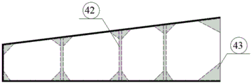
Fig. 6 is a side view of the box-type coupling beam member of the present invention.
Fig. 7 is a top view of the second embodiment of the present invention.
Fig. 8 is a side view of a second embodiment of the present invention.
Fig. 9 is a schematic view of an installation process according to a second embodiment of the present invention.
Fig. 10 is a structural diagram of a transition section center tube according to a second embodiment of the present invention.
Fig. 11 is a top view of a transition section center tube according to a second embodiment of the present invention.
Fig. 12 is a detailed view of the connection position between the suspension ring and the transition section central cylinder in the second embodiment of the present invention.
Fig. 13 is a top view of a third embodiment of the present invention.
Fig. 14 is a side view of a third embodiment of the present invention.
Fig. 15 is a schematic view of an installation process according to a third embodiment of the present invention.
In the figure:
1. a negative pressure suction bucket; 2. a water pumping hole; 3. a top stiffener; 4. a box-shaped connecting beam; 41. connecting the beam inner longitudinal partition plate; 42. a diaphragm plate in the connecting beam; 43. reinforcing rib plates in the connecting beam; 5. a transition section central barrel; 6. a hoisting ring; 7. locking; 8. anchor pulling in a prestress way; 9. a tension meter; 10. a local transverse stiffener plate; 11. a local longitudinal reinforcing floor; 12. a shear key in the barrel; 13. grouting layer in the cylinder, 14 and single pile.
Detailed Description
The invention is further described with reference to the accompanying drawings and the detailed description.
The first embodiment is as follows:
as shown in fig. 1 and 2, the utility model discloses a many barrels of combination foundation system that offshore wind-power box girder connects, including negative pressure suction bucket 1, changeover portion center section of thick bamboo 5 and box even roof beam 4. Three box-type connecting beams 4 are circumferentially and equidistantly arranged on the outer side of the transition section central cylinder 5. And a negative pressure suction barrel 1 is arranged below each box-shaped connecting beam 4.
A top reinforcing plate 3 is arranged between the box-type connecting beam 4 and the negative pressure suction barrel 1, the bottom surface of the top reinforcing plate 3 is connected with the top of each negative pressure suction barrel 1, the top surface of the top reinforcing plate 3 is connected with each box-type connecting beam 4, and the middle part of the top reinforcing plate 3 is provided with a through hole matched with a transition section central cylinder 5. The edge shape of the top reinforcing plate 3 between two adjacent box-type connecting beams 4 is an inward-concave arc shape. And water pumping holes 2 are respectively formed in the two sides of the box-shaped beam at the top of the negative pressure suction barrel.
As shown in fig. 4, 5 and 6, the box-type coupling beam 4 is a concrete-poured prefabricated member, and is internally provided with a coupling beam internal longitudinal partition plate 41, a coupling beam internal transverse partition plate 42 and a coupling beam internal reinforcing rib plate 43, the coupling beam internal longitudinal partition plate 41 is vertically arranged along the longitudinal direction of the box-type coupling beam 4, the coupling beam internal transverse partition plate 42 is vertically arranged perpendicular to the coupling beam internal longitudinal partition plate 41, and the coupling beam internal reinforcing rib plate 43 is arranged on the upper edge and the lower edge in the coupling beam. In order to guarantee the box even roof beam 4's bulk stiffness, the basic fatigue life who avoids appearing stress concentration and lead to reduces, the utility model discloses a box even roof beam 4 is inside to be set up even roof beam in longitudinal baffle 41 and even roof beam in diaphragm 42, guarantees the wholeness of even roof beam, and the welding or the component connection angular point of diaphragm 42 and box even roof beam 4 in longitudinal baffle 41 and even roof beam in even roof beam are provided with even roof beam in the reinforcing rib 43 to can avoid local stress concentration to appear, improve load transmission mechanism.
The technical scheme of the embodiment is suitable for the working conditions that the water depth is shallow or the buried depth of the seabed bedrock is shallow, and the wave current load is small. The tripod foundation of the bucket group is composed of three negative pressure suction buckets 1 and transmits the upper load to the seabed. The suction bucket forms the interior negative pressure of bucket through pumping hole 2, relies on the inside and outside pressure differential realization basis of bucket to penetrate. The three negative pressure suction buckets 1 are welded and connected into a whole through the top reinforcing plate 3, so that the integrity of the foundation is improved, the stress performance is improved, and meanwhile, the foundation component can be conveniently positioned, and the subsequent processing precision is ensured.
Compared with the traditional jacket form, the embodiment of the utility model adopts the box-type connecting beam 4 with simpler structure form, which can simplify the foundation design and clarify the load transmission path of the foundation system; the utility model discloses a negative pressure suction bucket 1, top reinforcing plate 3 and box are all through welded connection between the roof beam 4 in the patent, and the form is simple, and the component can carry out the modularization production, can greatly reduced design manufacturing cost, reduces construction cycle.
Fig. 3 is a schematic view of the installation process of this embodiment, and the specific construction process is as follows:
And 2, sinking through by self weight, namely sinking the tripod structure of the cluster bucket to the surface of the seabed, and finishing preliminary sinking through by the tripod structure of the cluster bucket under the action of the self weight.
And 3, performing suction penetration, after the self-weight penetration is finished, pumping the seawater in the suction barrel through the water pumping holes 2 to form an internal and external pressure difference and a seepage field, further finishing the penetration process of the tripod structure of the barrel group, and simultaneously further controlling the levelness of the foundation by controlling the water pumping speed of the three negative pressure suction barrels 1 in the installation process.
Example two:
the embodiment is a further optimization scheme based on the first embodiment, and in consideration of complex composition of offshore sea areas and large spatial variability of water depth in China, the following technical scheme is provided for resisting wave current load increase caused by water depth increase and ensuring the integral rigidity of the foundation:
as shown in fig. 7 and 8, the utility model discloses a many barrels of combination foundation system that offshore wind-power box girder connects, including negative pressure suction bucket 1, changeover portion center section of thick bamboo 5 and box even roof beam 4. Three box-type connecting beams 4 are circumferentially and equidistantly arranged on the outer side of the transition section central cylinder 5. And a negative pressure suction barrel 1 is arranged below each box-shaped connecting beam 4.
A top reinforcing plate 3 is arranged between the box-type connecting beam 4 and the negative pressure suction barrel 1, the bottom surface of the top reinforcing plate 3 is connected with the top of each negative pressure suction barrel 1, the top surface of the top reinforcing plate 3 is connected with each box-type connecting beam 4, and the middle part of the top reinforcing plate 3 is provided with a through hole matched with a transition section central cylinder 5. The edge shape of the top reinforcing plate 3 between two adjacent box-type connecting beams 4 is an inward-concave arc shape. And water pumping holes 2 are respectively formed in the two sides of the box-shaped beam at the top of the negative pressure suction barrel.
As shown in fig. 4, 5 and 6, the box-type coupling beam 4 is a concrete-poured prefabricated member, and is internally provided with a coupling beam internal longitudinal partition plate 41, a coupling beam internal transverse partition plate 42 and a coupling beam internal reinforcing rib plate 43, the coupling beam internal longitudinal partition plate 41 is vertically arranged along the longitudinal direction of the box-type coupling beam 4, the coupling beam internal transverse partition plate 42 is vertically arranged perpendicular to the coupling beam internal longitudinal partition plate 41, and the coupling beam internal reinforcing rib plate 43 is arranged on the upper edge and the lower edge in the coupling beam. In order to guarantee the box even roof beam 4's bulk stiffness, the basic fatigue life who avoids appearing stress concentration and lead to reduces, the utility model discloses a box even roof beam 4 is inside to be set up even roof beam in longitudinal baffle 41 and even roof beam in diaphragm 42, guarantees the wholeness of even roof beam, and the welding or the component connection angular point of diaphragm 42 and box even roof beam 4 in longitudinal baffle 41 and even roof beam in even roof beam are provided with even roof beam in the reinforcing rib 43 to can avoid local stress concentration to appear, improve load transmission mechanism.
As shown in fig. 10, 11 and 12, two annular local transverse reinforcing plates 10 are arranged on the inner wall of the transition section central cylinder 5, local longitudinal reinforcing ribs 11 are arranged between adjacent local transverse reinforcing plates 10, the local longitudinal reinforcing ribs 11 are equidistantly arranged around the inner wall of the transition section central cylinder 5, and the positions of the prestressed anchor 8 connected with the transition section central cylinder 5 correspond to the local longitudinal reinforcing ribs 11.
A hanging ring 6 is arranged around the outer side of the transition section central cylinder 5, the height of the hanging ring 6 is positioned between two adjacent local transverse reinforcing plates 10, and a local longitudinal reinforcing rib plate 11 is arranged on the inner side of the transition section central cylinder 5 at the corresponding position of the hanging ring 6; the top of the box-type connecting beam 4 far away from one end of the transition section central cylinder 5 is provided with a lock catch 7, one end of the prestress anchor 8 is connected with the hanging ring 6, and the other end of the prestress anchor is connected with the lock catch 7. One end of the prestress anchor 8 is connected with the tail end, far away from the transition section central cylinder 5, of the box-type connecting beam 4, the other end of the prestress anchor 8 is connected with the transition section central cylinder 5, and the horizontal projection of the prestress anchor 8 is overlapped with the central line of the box-type connecting beam 4. The prestressed anchor 8 is structurally provided with a tension meter 9. The prestressed anchorage 8 in this embodiment is made of a steel strand.
The central cylinder 5 of the transition section, the box-type connecting beam 4 at the lower part and the three suction buckets are connected into a whole, so that the length of a cantilever of the underwater foundation part is greatly reduced and the integral rigidity of the foundation is increased through the connection form; for the lifting ring 6 arranged at the upper part of the box-shaped connecting beam 4, in order to ensure the strength of local connection, the lifting ring 6 is required to be welded above the connecting beam inner longitudinal partition plate 41 of the box-shaped connecting beam 4; in contrast, the suspension ring 6 welded to the transition section central cylinder 5 is prevented from local destruction of the transition section central cylinder 5 due to stress concentration.
The utility model discloses a be provided with local horizontal reinforcing plate 10 and local vertical reinforcing floor 11 in the inside of a transition section center section of thick bamboo 5 corresponding position, guarantee rings 6 hookup location transition section center section of thick bamboo 5 at hoop and radial intensity and rigidity. In order to satisfy different rigidity demands in considering basic design, need adjust the pretension force of steel strand wires, the utility model discloses in be provided with tensiometer 9 on the prestressing force anchor 8, can guarantee the accuracy of pretension in the prestressing force anchor 8, simultaneously in the subsequent use in basis, can monitor the inside pulling force change of prestressing force anchor 8 for a long time, can reflect basic long-term bearing performance as the monitoring data side.
Fig. 9 is a schematic view of the installation process of this embodiment, and the specific construction process is as follows:
And 2, sinking through by self weight, namely sinking the tripod structure of the cluster bucket to the surface of the seabed, and finishing preliminary sinking through by the tripod structure of the cluster bucket under the action of the self weight.
And 3, performing suction penetration, after the self-weight penetration is finished, pumping the seawater in the suction barrel through the water pumping holes 2 to form an internal and external pressure difference and a seepage field, further finishing the penetration process of the tripod structure of the barrel group, and simultaneously further controlling the levelness of the foundation by controlling the water pumping speed of the three negative pressure suction barrels 1 in the installation process.
Example three:
the embodiment is a further optimization scheme based on the first embodiment, and considering that the strength of shallow soil bodies on the seabed in partial regions of the southeast sea area of China is low, the three negative pressure suction buckets 1 in the first embodiment cannot provide enough basic bearing capacity. For such a working condition, the present embodiment provides the following technical solutions on the basis of the first embodiment.
As shown in fig. 13 and 14, the utility model discloses a many barrels of combination foundation system that offshore wind-power box girder connects, including negative pressure suction bucket 1, single pile 14, changeover portion center section of thick bamboo 5 and box even roof beam 4. The transition section central cylinder 5 is sleeved outside the single pile 14. Three box-type connecting beams 4 are circumferentially and equidistantly arranged on the outer side of the transition section central cylinder 5. And a negative pressure suction barrel 1 is arranged below each box-shaped connecting beam 4.
A top reinforcing plate 3 is arranged between the box-type connecting beam 4 and the negative pressure suction barrel 1, the bottom surface of the top reinforcing plate 3 is connected with the top of each negative pressure suction barrel 1, the top surface of the top reinforcing plate 3 is connected with each box-type connecting beam 4, and the middle part of the top reinforcing plate 3 is provided with a through hole matched with a transition section central cylinder 5. The edge shape of the top reinforcing plate 3 between two adjacent box-type connecting beams 4 is an inward-concave arc shape. And water pumping holes 2 are respectively formed in the two sides of the box-shaped beam at the top of the negative pressure suction barrel.
As shown in fig. 4, 5 and 6, the box-type coupling beam 4 is a concrete-poured prefabricated member, and is internally provided with a coupling beam internal longitudinal partition plate 41, a coupling beam internal transverse partition plate 42 and a coupling beam internal reinforcing rib plate 43, the coupling beam internal longitudinal partition plate 41 is vertically arranged along the longitudinal direction of the box-type coupling beam 4, the coupling beam internal transverse partition plate 42 is vertically arranged perpendicular to the coupling beam internal longitudinal partition plate 41, and the coupling beam internal reinforcing rib plate 43 is arranged on the upper edge and the lower edge in the coupling beam. In order to guarantee the box even roof beam 4's bulk stiffness, the basic fatigue life who avoids appearing stress concentration and lead to reduces, the utility model discloses a box even roof beam 4 is inside to be set up even roof beam in longitudinal baffle 41 and even roof beam in diaphragm 42, guarantees the wholeness of even roof beam, and the welding or the component connection angular point of diaphragm 42 and box even roof beam 4 in longitudinal baffle 41 and even roof beam in even roof beam are provided with even roof beam in the reinforcing rib 43 to can avoid local stress concentration to appear, improve load transmission mechanism.
Preferably, a plurality of shear keys 12 in the transition section are arranged on the inner side of the central barrel 5 along the axial direction, and a grouting layer 13 in the barrel is poured in a space between the transition section central barrel 5 and the single pile 14.
The shear key 12 in the barrel and a barrel of a barrel tripod foundation are used as a mounting, positioning and pile stabilizing system of the single pile 14, and meanwhile, the integrity of the single pile 14 and the barrel tripod foundation is improved; the single pile 14 is connected with the transition section central cylinder 5 through a grouting layer 13 in the cylinder. Based on a group barrel tripod foundation in shallow sea, a large-diameter single pile 14-group barrel tripod composite foundation suitable for a soft seabed in offshore China is formed by combining structures such as a shear key 12 in a barrel, a grouting layer 13 in the barrel, a single pile 14 and the like.
Fig. 15 is a schematic view of the installation process in this embodiment, and the specific construction process is as follows:
And 2, sinking through by self weight, namely sinking the tripod structure of the cluster bucket to the surface of the seabed, and finishing preliminary sinking through by the tripod structure of the cluster bucket under the action of the self weight.
And 3, performing suction penetration, after the self-weight penetration is finished, pumping the seawater in the suction barrel through the water pumping holes 2 to form an internal and external pressure difference and a seepage field, further finishing the penetration process of the tripod structure of the barrel group, and simultaneously further controlling the levelness of the foundation by controlling the water pumping speed of the three negative pressure suction barrels 1 in the installation process.
and 5, grouting the nodes, namely driving the single piles 14 into a specified depth, and then performing grouting on the grouting layer 13 in the node grouting cylinder to ensure the integrity of the foundation.
Claims (10)
1. A multi-barrel combined foundation system connected with offshore wind power box-type beams is characterized by comprising a negative pressure suction barrel, a transition section center barrel and box-type connecting beams, wherein a plurality of box-type connecting beams are arranged on the outer side of the transition section center barrel at equal intervals around the circumference, and a negative pressure suction barrel is arranged below each box-type connecting beam.
2. The offshore wind power box girder connection multi-barrel combined foundation system as claimed in claim 1, wherein the box-type connecting girder is internally provided with a connecting girder inner longitudinal partition, a connecting girder inner transverse partition and a connecting girder inner reinforcing rib plate, the connecting girder inner longitudinal partition is vertically arranged along the longitudinal direction of the box-type connecting girder, the connecting girder inner transverse partition is vertically arranged perpendicular to the connecting girder inner longitudinal partition, and the upper edge and the lower edge in the connecting girder are provided with the connecting girder inner reinforcing rib plate.
3. The offshore wind power box girder connection multi-barrel combined foundation system as claimed in claim 1, wherein a top reinforcing plate is arranged between the box connecting beam and the negative pressure suction barrel, the bottom surface of the top reinforcing plate is connected with the top of each negative pressure suction barrel, the top surface of the top reinforcing plate is connected with each box connecting beam, and a through hole matched with the central barrel of the transition section is arranged in the middle of the top reinforcing plate.
4. The offshore wind power box girder connection multi-bucket combined foundation system according to claim 1, wherein the number of the negative pressure suction buckets and the box connecting girders is three.
5. The offshore wind power box girder connection multi-barrel combined foundation system according to claim 3, wherein the edge of the top reinforcing plate between two adjacent box connecting girders is shaped as an inwardly concave arc.
6. The offshore wind power box girder connected multi-bucket combined foundation system of claim 1, wherein the top of the negative pressure suction bucket is provided with water pumping holes at both sides of the box girder.
7. The offshore wind power box girder connection multi-barrel combined foundation system as claimed in claim 1, wherein the box coupling girder is provided at its distal end with a pre-stressed anchor, one end of the pre-stressed anchor is connected to the distal end of the box coupling girder away from the transition section central cylinder, the other end of the pre-stressed anchor is connected to the transition section central cylinder, and the horizontal projection of the pre-stressed anchor coincides with the center line of the box coupling girder.
8. The offshore wind power box girder connected multi-barrel combined foundation system according to claim 7, wherein the inner wall of the transition section central barrel is provided with at least two annular local transverse reinforcing plates, local longitudinal reinforcing ribs are arranged between adjacent local transverse reinforcing plates, the local longitudinal reinforcing ribs are equidistantly arranged around the inner wall of the transition section central barrel, and the prestressed anchor is connected with the transition section central barrel at a position corresponding to the local longitudinal reinforcing ribs.
9. The offshore wind power box girder connection multi-barrel combined foundation system according to claim 8, wherein a hanging ring is arranged around the outer side of the transition section central cylinder, the height of the hanging ring is between two adjacent local transverse reinforcing plates, and local longitudinal reinforcing ribs are arranged on the inner side of the transition section central cylinder at the corresponding positions of the hanging rings; the top of one end, away from the transition section center cylinder, of each box-type connecting beam is provided with a lock catch, one end of each prestress anchor is connected with the lifting ring, the other end of each prestress anchor is connected with the lock catch, and each prestress anchor is provided with a tension meter.
10. The offshore wind power box girder connection multi-barrel combined foundation system according to claim 1, wherein a single pile is sleeved in the transition section central barrel, a plurality of barrel inner shear keys are arranged on the inner wall of the transition section central barrel along the axial direction of the transition section central barrel, and a barrel inner grouting layer is poured in a space between the transition section central barrel and the single pile.
Priority Applications (1)
| Application Number | Priority Date | Filing Date | Title |
|---|---|---|---|
| CN201921370153.XU CN210766855U (en) | 2019-08-22 | 2019-08-22 | Multi-barrel combined foundation system connected with offshore wind power box-shaped beams |
Applications Claiming Priority (1)
| Application Number | Priority Date | Filing Date | Title |
|---|---|---|---|
| CN201921370153.XU CN210766855U (en) | 2019-08-22 | 2019-08-22 | Multi-barrel combined foundation system connected with offshore wind power box-shaped beams |
Publications (1)
| Publication Number | Publication Date |
|---|---|
| CN210766855U true CN210766855U (en) | 2020-06-16 |
Family
ID=71063556
Family Applications (1)
| Application Number | Title | Priority Date | Filing Date |
|---|---|---|---|
| CN201921370153.XU Active CN210766855U (en) | 2019-08-22 | 2019-08-22 | Multi-barrel combined foundation system connected with offshore wind power box-shaped beams |
Country Status (1)
| Country | Link |
|---|---|
| CN (1) | CN210766855U (en) |
Cited By (2)
| Publication number | Priority date | Publication date | Assignee | Title |
|---|---|---|---|---|
| CN112012237A (en) * | 2020-08-31 | 2020-12-01 | 河北工业大学 | Multi-cylinder reinforced composite single-pile foundation of offshore wind turbine and construction method |
| CN115059107A (en) * | 2022-06-30 | 2022-09-16 | 福建永福电力设计股份有限公司 | Grouting-free top plate structure of offshore wind power suction pile foundation and mounting method thereof |
-
2019
- 2019-08-22 CN CN201921370153.XU patent/CN210766855U/en active Active
Cited By (2)
| Publication number | Priority date | Publication date | Assignee | Title |
|---|---|---|---|---|
| CN112012237A (en) * | 2020-08-31 | 2020-12-01 | 河北工业大学 | Multi-cylinder reinforced composite single-pile foundation of offshore wind turbine and construction method |
| CN115059107A (en) * | 2022-06-30 | 2022-09-16 | 福建永福电力设计股份有限公司 | Grouting-free top plate structure of offshore wind power suction pile foundation and mounting method thereof |
Similar Documents
| Publication | Publication Date | Title |
|---|---|---|
| CN101545462B (en) | A steel-concrete combined weight type offshore wind fan foundation structure | |
| CN110453714B (en) | Offshore wind power jacket gravity type cylindrical foundation structure and construction method thereof | |
| CN103362113B (en) | Offshore wind farm, bridge and marine works local buoyancy ocean platform and construction method | |
| CN210766855U (en) | Multi-barrel combined foundation system connected with offshore wind power box-shaped beams | |
| CN110055995A (en) | A kind of offshore power generator foundation structure and its construction method | |
| CN201952809U (en) | Steel truss type offshore anemometer tower foundation structure | |
| CN103255752B (en) | Support the buoyant support fixed platform of offshore wind turbine, marine works | |
| CN111910673A (en) | Assembled offshore wind power barrel type foundation | |
| CN114855865A (en) | Tensioning type fan foundation anchored on rock-based seabed and arrangement method | |
| CN208870071U (en) | A kind of assembly gravity type offshore wind basis | |
| CN208763050U (en) | Offshore wind turbine gravity caisson basis | |
| CN106638662A (en) | Three-bucket-foundation combined foundation structure system of concrete supporting structure | |
| CN212336069U (en) | Deep sea wind power generation jacket type single pile composite structure | |
| CN112302046A (en) | Offshore wind power suction pile foundation additional top plate structure and installation method thereof | |
| CN211735478U (en) | Connecting structure of offshore wind power composite cylindrical foundation and tower barrel | |
| CN210562255U (en) | Offshore wind power cylinder type foundation underwater construction structure | |
| CN209941726U (en) | Offshore wind turbine single pile foundation reinforced pile foundation structure | |
| CN110616731A (en) | Multi-barrel combined foundation system connected with offshore wind power box-shaped beams | |
| CN217870596U (en) | Tensioning type fan foundation anchored on foundation seabed | |
| CN204491567U (en) | Pre-manufactured steel pile tube wind power generation platform | |
| CN103981894A (en) | Multi-cylindrical foundation combined foundation structure system | |
| CN210562259U (en) | Cylindrical side pile type offshore wind power foundation | |
| CN213038418U (en) | Novel all-steel cylindrical foundation structure for offshore wind power | |
| CN210212705U (en) | Offshore wind power floating foundation structure | |
| CN207919589U (en) | A kind of assembled steel barrel base structure |
Legal Events
| Date | Code | Title | Description |
|---|---|---|---|
| GR01 | Patent grant | ||
| GR01 | Patent grant |