CN210766845U - Assembled bracket foundation - Google Patents
Assembled bracket foundation Download PDFInfo
- Publication number
- CN210766845U CN210766845U CN201920849913.9U CN201920849913U CN210766845U CN 210766845 U CN210766845 U CN 210766845U CN 201920849913 U CN201920849913 U CN 201920849913U CN 210766845 U CN210766845 U CN 210766845U
- Authority
- CN
- China
- Prior art keywords
- rectangular column
- module
- foundation
- mortises
- connecting beam
- Prior art date
- Legal status (The legal status is an assumption and is not a legal conclusion. Google has not performed a legal analysis and makes no representation as to the accuracy of the status listed.)
- Withdrawn - After Issue
Links
- 239000000565 sealant Substances 0.000 claims abstract description 7
- 239000004570 mortar (masonry) Substances 0.000 claims description 4
- 238000012856 packing Methods 0.000 claims description 2
- 238000010276 construction Methods 0.000 abstract description 8
- 238000009434 installation Methods 0.000 abstract description 2
- 238000000034 method Methods 0.000 abstract description 2
- 230000008569 process Effects 0.000 abstract description 2
- 238000013461 design Methods 0.000 description 16
- 239000002689 soil Substances 0.000 description 9
- 238000004364 calculation method Methods 0.000 description 7
- 239000010410 layer Substances 0.000 description 7
- 230000005540 biological transmission Effects 0.000 description 6
- 230000008901 benefit Effects 0.000 description 5
- 238000012545 processing Methods 0.000 description 4
- 230000000694 effects Effects 0.000 description 3
- NJPPVKZQTLUDBO-UHFFFAOYSA-N novaluron Chemical compound C1=C(Cl)C(OC(F)(F)C(OC(F)(F)F)F)=CC=C1NC(=O)NC(=O)C1=C(F)C=CC=C1F NJPPVKZQTLUDBO-UHFFFAOYSA-N 0.000 description 3
- 238000004080 punching Methods 0.000 description 3
- 238000010008 shearing Methods 0.000 description 3
- 238000004458 analytical method Methods 0.000 description 2
- 238000009412 basement excavation Methods 0.000 description 2
- 238000005452 bending Methods 0.000 description 2
- 230000007797 corrosion Effects 0.000 description 2
- 238000005260 corrosion Methods 0.000 description 2
- 238000004519 manufacturing process Methods 0.000 description 2
- 238000012986 modification Methods 0.000 description 2
- 230000004048 modification Effects 0.000 description 2
- 239000011435 rock Substances 0.000 description 2
- 238000003466 welding Methods 0.000 description 2
- 229910000746 Structural steel Inorganic materials 0.000 description 1
- 238000010521 absorption reaction Methods 0.000 description 1
- 230000002411 adverse Effects 0.000 description 1
- 238000005266 casting Methods 0.000 description 1
- 239000002131 composite material Substances 0.000 description 1
- 230000006835 compression Effects 0.000 description 1
- 238000007906 compression Methods 0.000 description 1
- 230000007547 defect Effects 0.000 description 1
- 238000010586 diagram Methods 0.000 description 1
- 238000009826 distribution Methods 0.000 description 1
- 230000002349 favourable effect Effects 0.000 description 1
- 230000005484 gravity Effects 0.000 description 1
- XEEYBQQBJWHFJM-UHFFFAOYSA-N iron Substances [Fe] XEEYBQQBJWHFJM-UHFFFAOYSA-N 0.000 description 1
- 229910052742 iron Inorganic materials 0.000 description 1
- 239000002184 metal Substances 0.000 description 1
- 229910052751 metal Inorganic materials 0.000 description 1
- 230000035699 permeability Effects 0.000 description 1
- 238000003825 pressing Methods 0.000 description 1
- 230000001105 regulatory effect Effects 0.000 description 1
- 230000002787 reinforcement Effects 0.000 description 1
- 239000004576 sand Substances 0.000 description 1
- 230000035939 shock Effects 0.000 description 1
- 239000002356 single layer Substances 0.000 description 1
- 239000004575 stone Substances 0.000 description 1
- XLYOFNOQVPJJNP-UHFFFAOYSA-N water Substances O XLYOFNOQVPJJNP-UHFFFAOYSA-N 0.000 description 1
Images


Abstract
The assembly type bucket arch foundation mainly comprises a tower foot plate base and a prefabricated body fixedly connected with the tower foot plate base, wherein the prefabricated body comprises a rectangular column module and a longitudinal and transverse hollow beam module arranged at the bottom of the rectangular column module, a group of mortises are formed in the bottom of the rectangular column module, bolt through holes are longitudinally formed in the rectangular column module, and the tower foot plate base is fixedly connected with the rectangular column module through bolts; tenons which correspond to the mortises at the bottoms of the rectangular column modules in number and are matched in shape are arranged at the tops of the hollow beam modules, the rectangular column modules are in mortise and tenon connection with the hollow beam modules, and filling sealant is arranged between the mortises and the tenons at the connection positions; the construction method has the characteristics of reasonable structural type stress, safe and reliable connection, convenient construction and installation, realization of no-moisture full mechanization in the construction process, reasonable technical and economic indexes and the like.
Description
Technical Field
The utility model relates to a transmission line technical field, concretely relates to assembled bracket basis.
Background
In the engineering design of the power transmission line, the selection of the foundation type is comprehensively determined according to factors such as the type of a tower, the terrain along the line, the geological conditions at the position of the tower, construction and transportation and the like in combination with the characteristics of loads. The basic pattern can be generally divided into: excavation backfill foundation (rigid step foundation, flexible plate type foundation), undisturbed soil foundation (excavation type foundation, cast-in-place pile foundation, rock anchor rod foundation and rock embedded foundation), assembly type foundation and the like. The pole tower foundation is used as an important component of the power transmission line, and the quality of the foundation design directly influences the manufacturing cost, the construction period and the labor consumption of the whole line project.
At present, in the assembly type foundation widely popularized, common types are all-metal assembly type foundations and assembly type foundations combined by concrete laths and angle iron supports, and the core advantage is that a foundation body can be prefabricated in a factory and can be assembled without casting on site, so that the construction efficiency and the economic benefit are greatly improved in areas which are not limited by external environments, particularly areas which are difficult to collect water and sand and stones and have good transportation conditions. At present, in the foundation engineering of the power transmission line, the conventional assembly type foundation prefabricated parts are mainly connected by bolts, and in addition, the welding connection and the pin bolt connection are common in the pile foundation. However, such a connection part is prone to corrosion damage of a connection screw or a welding seam, has corrosion hidden trouble, and cannot ensure integrity of a foundation, so that effective exertion of stress performance and safety and reliability of foundation engineering cannot be guaranteed. Therefore, the processing and construction processes of the prefabricated assembly foundation, particularly the assembling and connecting modes of the components, affect and even determine the safety and feasibility of the foundation. A convenient and fast prefabricated part processing and reliable and durable connection mode is to develop a novel basic type breakthrough.
Disclosure of Invention
The to-be-solved technical problem of the utility model lies in, to the above-mentioned defect of prior art, it is reasonable to provide a structural style atress, connects safe and reliable, and construction simple to operate can realize that the work progress does not have wet full mechanization and the reasonable assembled bracket basis of technical and economic index.
The utility model aims at providing an assembled bracket foundation which mainly comprises a pedestal base and a prefabricated part fixedly connected with the pedestal base, wherein the prefabricated part comprises a rectangular column module and a longitudinal and transverse hollow beam module arranged at the bottom of the rectangular column module, the bottom of the rectangular column module is provided with a group of mortises, bolt through holes are longitudinally arranged in the rectangular column module, and the pedestal base is fixedly connected with the rectangular column module through bolts; the top of fretwork roof beam module be provided with the tongue-and-groove quantity of rectangle post module bottom corresponds and the tenon that the shape matches, rectangle post module and fretwork roof beam module mortise-tenon joint, and is provided with the packing sealant between the tongue-and-groove of junction and tenon.
Furthermore, the hollow beam module comprises a plurality of bottom beams, a first connecting beam, a second connecting beam, a third connecting beam and a top beam which are arranged in a criss-cross mode from bottom to top in sequence, the cross section of each bottom beam is in an inverted T shape, the bottom of each bottom beam is a supporting seat, and the top of each bottom beam is provided with at least three tenons; the cross sections of the first connecting beam, the second connecting beam, the third connecting beam and the top beam are all rectangular, mortises corresponding to the bottom beams in number are formed in the bottom of the first connecting beam, and at least two tenons are arranged at the top of the first connecting beam; mortises with the number corresponding to that of the first connecting beams are formed in the bottom of the second connecting beam, and at least two tenons are arranged at the top of the second connecting beam; the bottom parts of the third connecting beam and the top beam are provided with at least two mortises, and the middle position of the top parts of the third connecting beam and the top beam is provided with at least one tenon; the bottom of the rectangular column module is provided with two mortises, and the top beam is clamped with the mortises at the bottom of the rectangular column module through tenons arranged at the top.
Further, the filling sealant is high-strength self-compacting mortar.
The utility model has the advantages of: the utility model discloses the structural grouping is reasonable, uses traditional mortise-tenon joint fill arch structure pressure-bearing, good mechanical properties in the aspect of shearing, the shock absorption, prefabricated different self-connections of T type fretwork roof beam cross-section realization prefabricated foundation component are moved about freely and quickly ingeniously, through hoist and mount sliding mode realization basis draw, press the atress demand. In the aspect of detail structure treatment, gaps are reserved at the joints of the beam bodies properly, high-strength self-compacting mortar is sprayed and filled, and the overall rigidity and integrity are improved.
Drawings
Fig. 1 is a schematic perspective view of the present invention;
fig. 2 is a schematic plan view of the present invention;
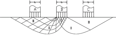
FIG. 3 is a stress profile of the bottom bearing strip;
FIG. 4 is a schematic view of a calculated area of a foundation slab of a matched bucket arch;
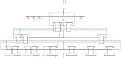
FIG. 5 is a schematic diagram of pre-deviation of longitudinal and transverse beams of an assembled bucket arch foundation.
Detailed Description
To make the objects, technical solutions and advantages of the present invention more clearly understood by those skilled in the art, the present invention will be further described with reference to the accompanying drawings and examples.
As shown in fig. 1-2, the assembly type bucket arch foundation of the present invention mainly comprises a tower footing plate base and a prefabricated body 1 fixedly connected with the tower footing plate base, wherein the prefabricated body 1 comprises a rectangular column module 2 and a longitudinal and transverse hollow beam module 3 arranged at the bottom of the rectangular column module 2, a group of mortises are formed at the bottom of the rectangular column module 2, bolt through holes are longitudinally formed in the rectangular column module 2, and the tower footing plate base is fixedly connected with the rectangular column module 2 through bolts; tenons which correspond to the mortises at the bottom of the rectangular column module 2 in number and are matched in shape are arranged at the top of the hollow beam module 3, the rectangular column module 2 is in mortise and tenon connection with the hollow beam module 3, and filling sealant is arranged between the mortises and the tenons at the connection part; the number of beam members and the number of staggered layers of the longitudinal and transverse hollow beam modules 3 are determined by load requirements and geological parameters in a modularized mode.
Referring to fig. 1, the hollow beam module 3 includes a plurality of bottom beams 4, a first connecting beam 5, a second connecting beam 6, a third connecting beam 7 and a top beam 8, which are arranged in a criss-cross manner from bottom to top in sequence, the cross section of each bottom beam 4 is in an inverted T shape, the bottom of each bottom beam 4 is provided with a supporting seat 9, and the top of each bottom beam 4 is provided with at least three tenons; the cross sections of the first connecting beam 5, the second connecting beam 6, the third connecting beam 7 and the top beam 8 are all rectangular, mortises corresponding to the bottom beams 4 in number are formed in the bottom of the first connecting beam 5, and at least two tenons are arranged at the top of the first connecting beam 5; mortises with the number corresponding to that of the first connecting beams 5 are formed in the bottom of the second connecting beam 6, and at least two tenons are arranged at the top of the second connecting beam 6; at least two mortises are formed in the bottoms of the third connecting beam 7 and the top beam 8, and at least one tenon is arranged in the middle of the top 8 of the third connecting beam 7 and the top beam; the bottom of rectangular column module 2 is provided with two tongue-and-grooves, back timber 8 is through the tenon and the tongue-and-groove joint of rectangular column module 2 bottom that the top set up. The filling sealant is high-strength self-compacting mortar.
The calculation of the bearing capacity of the lower pressing foundation and the bearing capacity of the upper pulling foundation is similar to that of a conventional plate type foundation, and is designed according to a related calculation method in the technical specification of overhead transmission line foundation design (DL/T5219-2014).
(1) Downward pressure bearing capacity of assembled bucket arch foundation
The press bearing capacity of the fabricated foundation is calculated according to the whole area surrounded by the bottom plate battens, and the distribution of the press bearing stress of the bottom battens is shown in figure 3. For the assembled bucket arch foundation applied to the project, the soil body prepressing and tamping functions are considered, the longitudinal and transverse beam system plays an integral effect, and the integral area surrounded by the bottom I-shaped beam is taken as A in the following calculation formula, which is shown in figure 4.
1) When the axle center load acts, the following requirements are met:
γrfP≤fα
p-design value of mean pressure at the basal floor, kPa;
γrf-a foundation bearing capacity adjustment factor, taking 0.75;
fαthe corrected characteristic value of the bearing capacity of the foundation is regulated according to the relevant regulations of the national standard 'design Specification of Foundation for buildings' GB 50007.
2) When the eccentric load acts, the following requirements are met:
γrfPmax≤1.2fα
Pmaxdesign value of maximum pressure at the base bottom edge.
a. Axle center load of foundation bottom surface

F-design value of vertical pressure transmitted by the superstructure to the top surface of the foundation;
g-weight of foundation and weight of soil on foundation
A is the area of the base bottom surface
γGThe coefficient of the permanent load component, when it is favorable to the foundation, is preferably gammaGWhen the ratio is 1.0, disadvantageously, γ should be takenG=1.2。
b. Eccentric load of foundation bottom surface

Mx、My-design values of moments acting on the base bottom surface in the X and Y directions;
Wx、Wy-the moments of resistance of the base bottom around the X and Y axes;
Pminminimum design pressure of base bottom edge
(2) Pulling-up stability of assembled bucket arch foundation
According to the range of the uplift angle of the foundation soil, the effective uplift soil range of the bottom beams is wrapped on the soil on the upper part of the foundation by reasonably arranging the clear distance between the bottom beams, namely the self weight of the foundation and the soil on the upper part of the foundation resist the uplift force together.
And (3) based on the stable calculation formula:
γfTE≤γEγSγs1(Vt-ΔVt-V0)+Gf
γfthe basis additional subentry coefficient is determined according to the overhead transmission line basis design technical regulation table 3.0.16;
TK-design value of pull-out force on basis;
γE-a horizontal force influence coefficient, which is taken from the ratio of horizontal force to pull-up force; determined according to the regulation table 4.2.1-1;
γs-a weighted average gravity of the soil above the basal bottom surface;
γs1-the coefficient of influence of the slope angle of the upper plane of the foundation slab, γ when the slope angle θ 1 < 45 °eWhen the slope angle theta 1 is greater than or equal to 45 degrees, gamma is 0.8e=1.0:
Vt-htThe volume of soil and foundation in depth;
ΔVt-micro-volume of adjacent basis influences;
V0-hta base volume within depth;
Gf-basis weight;
1) square bottom plate VtCalculating the formula:
when h is generatedt≤hcTime of flight

When h is generatedt≥hcTime of flight

hc-determined according to protocol table 4.3.1-1;
α -upward pulling the corner, determined according to the regulation table 4.3.1-2;
b-square base plate width
D-width of circular foundation slab
2)ΔVtFormula for calculation
When L is less than D +2httan α

L-iron tower foundation root
(3) Self strength of assembled bucket arch foundation
The longitudinal and transverse beam systems of the foundation bear the bending moment, shearing force and punching force of the foundation in the x direction and the y direction. And (3) carrying out normal section, oblique section, punching and local compression bearing capacity calculation on the single beam member, wherein a specific formula refers to the sixth section of concrete structure design Specification GB 50010-2010.
And (3) calculating the shear-resistant bearing capacity of the connecting part of the prefabricated bucket arch foundation layer by layer according to the following formula:
V≤0.25βcfcbh0
maximum shear design value on the V-member oblique section;
βc-a concrete strength influence coefficient;
b-the width of the rectangular cross-section;
h0-a cross-sectional effective height;
according to the effects of a design value 2060kN of the lower pressure and a design value 1740kN of the upper pulling force of a tower type 5A2-JC4, the buried depth of the foundation of the assembled bucket arch is 3m, the section size (the height of an upper flange X and a lower flange X) of a bottom layer beam is 500mmX700mmX600mm, and the total length of the beam is 7 m. The strength requirement of the foundation is met, and the cross section size of the bending-resistant, shearing-resistant and punching-resistant connecting part of the longitudinal and transverse beams is designed to be 100mmX300 mm.
To reduce the adverse effect of horizontal forces on the foundation and thereby reduce the size and reinforcement of the longitudinal and transverse beams, the center positions of the longitudinal and transverse beams can be adjusted to make the entire bucket arch foundation assume a pre-eccentric configuration, as shown in fig. 5.
Analysis of economic indicators
Similarly, take 5a2-JC4 as an example (the foundation acting force is shown in table 1), and a traditional plate foundation is adopted, and the calculated specification is BD3070, that is, the burying depth is 3.0m, the plate width is 7.0m, the foundation upright post width is 1.2m, the bottom plate height h1 is 0.95m, the h2 is 0.25m, and the foundation outcrop is 0.5 m; according to the calculation and analysis of the previous section, the bucket arch foundation is optimized into a beam system structure, the structure can be replaced by an upper longitudinal precast beam and a lower longitudinal precast beam which are vertical to each other and a middle precast base, the structure is divided into five layers of beams, the total buried depth of the foundation is 3.0m, the length of a bottom layer beam is 7.0m, the height of a single layer beam is 0.6m, and the size of each layer of precast beam is shown in the following table 2. The specific configurations of the two bases are shown in table 3.


TABLE 15A 2-JC4 base forces

TABLE 25A 2-JC4 fabricated bucket arch foundation layered dimension table

TABLE 35A 2-JC4 basic configuration Table
From the above table, it can be seen that with the fabricated bucket arch foundation, the concrete volume is reduced by 58% compared with the traditional plate type foundation. The grade of the concrete of the bucket arch foundation is improved from C25 to C40, and according to the current information price, when the single price of the concrete is measured, the prefabricated foundation is 1.33 times of the cast-in-place foundation; considering that the processing and the installation of the prefabricated basic components are complex, the processing and the assembling cost of the single piece is improved by about 2 times. The comprehensive cost of the prefabricated bucket arch foundation is reduced by about 18.5 percent compared with the conventional cast-in-place plate foundation. In conclusion, compared with the traditional plate foundation, the permeability design of the composite plate foundation has the advantages that the formula amount is greatly reduced by about 58% and the comprehensive manufacturing cost is reduced by about 18.5% in technical and economic indexes.
The specific embodiments described herein are merely illustrative of the principles of the present invention and its efficacy, and are not intended to limit the invention. Modifications and variations can be made to the above-described embodiments by those skilled in the art without departing from the spirit and scope of the present invention. Therefore, it is intended that all equivalent modifications or changes which can be made by those skilled in the art without departing from the spirit and technical idea of the present invention shall be covered by the claims of the present invention.
Claims (3)
1. The assembly type bucket arch foundation mainly comprises a tower foot plate base and a prefabricated body fixedly connected with the tower foot plate base, and is characterized in that the prefabricated body comprises a rectangular column module and a longitudinal and transverse hollow beam module arranged at the bottom of the rectangular column module, a group of mortises are formed in the bottom of the rectangular column module, bolt through holes are longitudinally formed in the rectangular column module, and the tower foot plate base is fixedly connected with the rectangular column module through bolts; the top of fretwork roof beam module be provided with the tongue-and-groove quantity of rectangle post module bottom corresponds and the tenon that the shape matches, rectangle post module and fretwork roof beam module mortise-tenon joint, and is provided with the packing sealant between the tongue-and-groove of junction and tenon.
2. The assembly type bucket arch foundation of claim 1, wherein the hollowed-out beam module comprises a plurality of bottom beams, a first connecting beam, a second connecting beam, a third connecting beam and a top beam which are arranged in a criss-cross manner from bottom to top in sequence, the cross section of each bottom beam is in an inverted T shape, the bottom of each bottom beam is a supporting seat, and the top of each bottom beam is provided with at least three tenons; the cross sections of the first connecting beam, the second connecting beam, the third connecting beam and the top beam are all rectangular, mortises corresponding to the bottom beams in number are formed in the bottom of the first connecting beam, and at least two tenons are arranged at the top of the first connecting beam; mortises with the number corresponding to that of the first connecting beams are formed in the bottom of the second connecting beam, and at least two tenons are arranged at the top of the second connecting beam; the bottom parts of the third connecting beam and the top beam are provided with at least two mortises, and the middle position of the top parts of the third connecting beam and the top beam is provided with at least one tenon; the bottom of the rectangular column module is provided with two mortises, and the top beam is clamped with the mortises at the bottom of the rectangular column module through tenons arranged at the top.
3. The fabricated bucket arch foundation of claim 2, wherein the filling sealant is a high strength self-compacting mortar.
Priority Applications (1)
| Application Number | Priority Date | Filing Date | Title |
|---|---|---|---|
| CN201920849913.9U CN210766845U (en) | 2019-06-06 | 2019-06-06 | Assembled bracket foundation |
Applications Claiming Priority (1)
| Application Number | Priority Date | Filing Date | Title |
|---|---|---|---|
| CN201920849913.9U CN210766845U (en) | 2019-06-06 | 2019-06-06 | Assembled bracket foundation |
Publications (1)
| Publication Number | Publication Date |
|---|---|
| CN210766845U true CN210766845U (en) | 2020-06-16 |
Family
ID=71062872
Family Applications (1)
| Application Number | Title | Priority Date | Filing Date |
|---|---|---|---|
| CN201920849913.9U Withdrawn - After Issue CN210766845U (en) | 2019-06-06 | 2019-06-06 | Assembled bracket foundation |
Country Status (1)
| Country | Link |
|---|---|
| CN (1) | CN210766845U (en) |
Cited By (1)
| Publication number | Priority date | Publication date | Assignee | Title |
|---|---|---|---|---|
| CN110318414A (en) * | 2019-06-06 | 2019-10-11 | 浙江华云电力工程设计咨询有限公司 | A kind of assembled sets of brackets on top of the columns basis |
-
2019
- 2019-06-06 CN CN201920849913.9U patent/CN210766845U/en not_active Withdrawn - After Issue
Cited By (2)
| Publication number | Priority date | Publication date | Assignee | Title |
|---|---|---|---|---|
| CN110318414A (en) * | 2019-06-06 | 2019-10-11 | 浙江华云电力工程设计咨询有限公司 | A kind of assembled sets of brackets on top of the columns basis |
| CN110318414B (en) * | 2019-06-06 | 2024-01-23 | 浙江华云电力工程设计咨询有限公司 | Assembled bucket arch foundation |
Similar Documents
| Publication | Publication Date | Title |
|---|---|---|
| CN202831402U (en) | Concrete filled steel tubular column with inner-connected circular pipe and outer-sleeved concrete filled steel tube | |
| CN203080965U (en) | Intelligent steel structure anti-seismic villa | |
| CN201411824Y (en) | Direct assembled steel pipe concrete combination special-shaped column | |
| CN201288328Y (en) | Fixed foundation for beam and plate integrated prefabricated split mounting type tower crane | |
| CN111962952A (en) | Steel tube concrete column-H-shaped steel beam-steel support-pi-shaped connecting piece combined type center pillar bottom node and manufacturing method | |
| CN212128825U (en) | Assembled integrated pier column and bent cap combined structure | |
| CN103174260A (en) | Crossed steel concrete specially-shaped column with angle steel framework | |
| CN210766845U (en) | Assembled bracket foundation | |
| CN106284644B (en) | A kind of residential architecture structural system and its method of construction suitable for industrialized production | |
| CN202730749U (en) | Prefabricated reinforced concrete H-shaped support pile | |
| CN103195212A (en) | T-shaped steel reinforced concrete special-shaped column of supporting steel frame | |
| CN203334423U (en) | Rebar joint structure of prefabricated stacked balcony slab and main body | |
| CN110130485B (en) | Prefabricated assembly type beam column node with toothed plates and assembly method thereof | |
| CN204059756U (en) | The truss of a kind of pre-stressed steel pipe concrete purlin sheet and structure thereof | |
| CN111962951A (en) | Steel tube concrete column-H-shaped steel beam-steel support-Pi-shaped connecting piece combined type corner column bottom node and manufacturing method | |
| CN111794421A (en) | Assembled precast concrete floor | |
| CN104452798B (en) | Offshore wind turbine foundation structure and equipment and construction method of offshore wind turbine foundation equipment | |
| CN110939218A (en) | Assembled profiled steel sheet composite shear wall and construction method thereof | |
| CN115839102A (en) | Wind power tower prestress stiffening type steel concrete high-rise pile cap foundation | |
| CN113279423B (en) | Prefabricated column pier and post-cast strip foundation beam assembly integral construction method | |
| CN110318414B (en) | Assembled bucket arch foundation | |
| CN214461175U (en) | Large-span special-shaped steel structure building | |
| CN112177041B (en) | Underground space prefabricated and assembled integral structure and construction method thereof | |
| CN201512803U (en) | Structural layer used for preventing building from sinking and bottom layer structure in transformer substation | |
| CN216075723U (en) | Connector convenient to connect assembled composite wall |
Legal Events
| Date | Code | Title | Description |
|---|---|---|---|
| GR01 | Patent grant | ||
| GR01 | Patent grant | ||
| AV01 | Patent right actively abandoned | ||
| AV01 | Patent right actively abandoned | ||
| AV01 | Patent right actively abandoned |
Granted publication date: 20200616 Effective date of abandoning: 20240123 |
|
| AV01 | Patent right actively abandoned |
Granted publication date: 20200616 Effective date of abandoning: 20240123 |