CN210737931U - Architectural design roof eaves mouth watertight fittings - Google Patents
Architectural design roof eaves mouth watertight fittings Download PDFInfo
- Publication number
- CN210737931U CN210737931U CN201920975671.8U CN201920975671U CN210737931U CN 210737931 U CN210737931 U CN 210737931U CN 201920975671 U CN201920975671 U CN 201920975671U CN 210737931 U CN210737931 U CN 210737931U
- Authority
- CN
- China
- Prior art keywords
- water
- tank
- water tank
- filtering
- sets
- Prior art date
- Legal status (The legal status is an assumption and is not a legal conclusion. Google has not performed a legal analysis and makes no representation as to the accuracy of the status listed.)
- Active
Links
Images


Classifications
-
- Y—GENERAL TAGGING OF NEW TECHNOLOGICAL DEVELOPMENTS; GENERAL TAGGING OF CROSS-SECTIONAL TECHNOLOGIES SPANNING OVER SEVERAL SECTIONS OF THE IPC; TECHNICAL SUBJECTS COVERED BY FORMER USPC CROSS-REFERENCE ART COLLECTIONS [XRACs] AND DIGESTS
- Y02—TECHNOLOGIES OR APPLICATIONS FOR MITIGATION OR ADAPTATION AGAINST CLIMATE CHANGE
- Y02A—TECHNOLOGIES FOR ADAPTATION TO CLIMATE CHANGE
- Y02A20/00—Water conservation; Efficient water supply; Efficient water use
- Y02A20/108—Rainwater harvesting
Abstract
The utility model discloses a building design roof cornice waterproof device, which comprises a house body and a storage water tank, wherein the top of the house body is provided with a roof, one side of the house body is respectively provided with a collecting tank, a fixing box and a filtering water tank, the bottom of the collecting tank is provided with a water drainage tank, the top of the filtering water tank is provided with a water inlet funnel, a filtering plate is arranged inside the water inlet funnel, the lower surface of the filtering water tank is provided with a water outlet funnel, and a filtering sponge is arranged inside the water outlet funnel; by the designed filter water tank, the storage water tank and the solar water tank, the utilization rate of water resources of the device can be fully improved, the device is reasonable in design and simple in structure, more clean rainwater can be obtained, and waste of water resources is avoided; through the clamping mechanism who designs, be convenient for dismantle and install the drainage plate, convenient the change, convenient operation, labour saving and time saving.
Description
Technical Field
The utility model belongs to the technical field of the building is waterproof, concretely relates to architectural design roof eaves mouth watertight fittings.
Background
The cornice is a typical horizontal component with line feet and convex at the top in a building composition, the cornice is often mistakenly made as a 'edge', a general roof cornice is the upper edge of the cornice at the outermost edge of a large roof, namely an 'upper edge', and the cornice is particularly the uppermost part of three parts of the cornice of a classical building; among the existing device, have the function of collecting the rainwater very seldom, can not fully improve the utilization ratio of water resource, lead to the rainwater to be useless, the drainage plate time in the device is used for a long time the back moreover, and it is loaded down with trivial details to dismantle, inconvenient change, the problem that can appear the emergence of the damaged condition easily, for this we propose a architectural design roof eaves mouth watertight fittings.
SUMMERY OF THE UTILITY MODEL
An object of the utility model is to provide an architectural design roof eaves mouth watertight fittings to in solving the current device that proposes in the above-mentioned background art, have the function of collecting the rainwater very few, can not fully improve the utilization ratio of water resource, lead to the rainwater to be useless, the drainage plate time in the device is with having been of a specified duration in addition after, it is loaded down with trivial details to dismantle, inconvenient change, the problem of the emergence of the damaged condition can appear easily.
In order to achieve the above object, the utility model provides a following technical scheme: a building design roof cornice waterproof device comprises a house body and a storage water tank, wherein the top of the house body is provided with a roof, one side of the house body is respectively provided with a collecting tank, a fixing box and a filtering water tank, the bottom of the collecting tank is provided with a water drainage tank, the top of the filtering water tank is provided with a water inlet funnel, a filtering plate is arranged in the water inlet funnel, the lower surface of the filtering water tank is provided with a water outlet funnel, a filtering sponge is arranged in the water outlet funnel, a connecting pipe is arranged between the water outlet funnel and the storage water tank, the bottom of the storage water tank is provided with a bottom plate and an embedded rod, four groups of supporting columns are arranged between the storage water tank and the embedded rod, the upper surface of the bottom plate is provided with a support, the top of the support is provided with a solar water tank, the solar water tank is, the solar water tank is characterized in that a support plate is arranged on the support, a water pump is arranged on the upper surface of the support plate, a first water pipe is arranged between the water pump and the solar water tank, and a second water pipe is arranged between the water pump and the water storage tank.
Preferably, be provided with chucking mechanism on the fixed box, chucking mechanism includes the drainage plate, the drainage plate bottom is provided with two sets of embedded pieces, fixed box is inside to have seted up two sets of first cavitys, and is two sets of the inside embedding pole that is provided with of first cavity, embedding pole outer wall overlaps respectively and is equipped with compression spring and retaining ring, the embedding pole outside is provided with the pull ring, two sets of confessions have still been seted up to the drainage plate inside the second cavity of embedding pole tip embedding and confession the recess of two sets of embedded piece bottom embedding.
Preferably, one side of the solar water tank is provided with a water outlet pipe, the bottom of the storage water tank is provided with a water drain pipe, and the water outlet pipe and the water drain pipe are both provided with control valves.
Preferably, a water level measuring instrument is arranged on the storage water tank.
Preferably, a waterproof layer is arranged outside the house body.
Compared with the prior art, the beneficial effects of the utility model are that:
(1) through the filtration water tank, storage water pitcher, solar energy water tank of design, can fully improve the device's water resource utilization rate, reasonable in design, simple structure can obtain more clean rainwater, avoids the water resource waste.
(2) Through the clamping mechanism who designs, be convenient for dismantle and install the drainage plate, convenient the change, convenient operation, labour saving and time saving.
Drawings
Fig. 1 is a schematic structural view of the present invention;
FIG. 2 is a schematic view of the connection structure of the water storage tank and the solar water tank of the present invention;
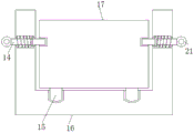
FIG. 3 is a schematic structural view of the chucking mechanism of the present invention;
fig. 4 is a schematic structural view of the water inlet funnel of the present invention;
FIG. 5 is a schematic view of the structure of the launching funnel of the present invention;
fig. 6 is an enlarged schematic view of the structure at a of the present invention;
in the figure: 1. a support; 2. a water pump; 3. a solar water tank; 4. a connecting pipe; 5. a launching funnel; 6. a filtering water tank; 7. a water inlet funnel; 8. a roof; 9. a waterproof layer; 10. a house body; 11. a water storage tank; 12. a base plate; 13. a water level measuring instrument; 14. an embedded rod; 15. embedding a block; 16. a fixing box; 17. a drainage plate; 18. a filter plate; 19. filtering the sponge; 20. Collecting tank; 21. and (4) a pull ring.
Detailed Description
The technical solutions in the embodiments of the present invention will be described clearly and completely with reference to the accompanying drawings in the embodiments of the present invention, and it is obvious that the described embodiments are only some embodiments of the present invention, not all embodiments. Based on the embodiments in the present invention, all other embodiments obtained by a person skilled in the art without creative work belong to the protection scope of the present invention.
Referring to fig. 1-6, the present invention provides a technical solution: a building design roof cornice waterproof device comprises a house body 10 and a storage water tank 11, wherein the top of the house body 10 is provided with a roof 8, one side of the house body 10 is respectively provided with a collecting tank 20, a fixing box 16 and a filtering water tank 6, the bottom of the collecting tank 20 is provided with a water discharging tank, the top of the filtering water tank 6 is provided with a water inlet funnel 7, the inside of the water inlet funnel 7 is provided with a filtering plate 18, the lower surface of the filtering water tank 6 is provided with a water outlet funnel 5, the inside of the water outlet funnel 5 is provided with a filtering sponge 19, a connecting pipe 4 is arranged between the water outlet funnel 5 and the storage water tank 11, the bottom of the storage water tank 11 is provided with a bottom plate 12, the building design roof cornice waterproof device also comprises an embedded rod 14, four groups of supporting columns are arranged between the storage water tank 11 and, be provided with two sets of bolts on two sets of clamps respectively, be provided with the backup pad on the support 1, the backup pad upper surface is provided with water pump 2, be provided with first water pipe between water pump 2 and the solar energy water tank 3, be provided with the second water pipe between water pump 2 and the storage water tank 11, filter tank 6 through the design, storage water tank 11, solar energy water tank 3, can fully improve the device's water resource utilization ratio, reasonable in design, simple structure can obtain more clean rainwater, avoid water resource waste.
In this embodiment, it is preferred, be provided with chucking mechanism on the fixed box 16, chucking mechanism includes drainage plate 17, drainage plate 17 bottom is provided with two sets of embedded pieces 15, fixed box 16 is inside to have seted up two sets of first cavitys, the inside embedding pole 14 that is provided with of two sets of first cavitys, the 14 outer walls of embedding pole are overlapped respectively and are equipped with compression spring and confinement ring, the embedding pole 14 outside is provided with pull ring 21, the inside second cavity that still sets up two sets of confession embedded pole 14 tip embedding and the recess that supplies the 15 bottoms of two sets of embedded pieces to imbed of drainage plate 17, chucking mechanism through the design, be convenient for dismantle and install drainage plate 17, convenient change, and convenient for operation, and is time-saving and labor-.
In this embodiment, preferably, a water outlet pipe is arranged on one side of the solar water tank 3, a water discharge pipe is arranged at the bottom of the water storage tank 11, and control valves are arranged on the water outlet pipe and the water discharge pipe.
In this embodiment, it is preferable that the water level measuring instrument 13 is provided on the storage water tank 11.
In this embodiment, it is preferred, house body 10 outside is provided with waterproof layer 9, and through the waterproof layer 9 that sets up, can effectively carry out waterproofly to the roof eaves mouth, prevents that the rainwater seepage from causing the damage to the house.
The utility model discloses a theory of operation and use flow:
the water level measuring instrument used by the utility model has 13 models of HLG-50; when the device collects rainwater, the rainwater falls on the roof 8, then the rainwater enters the collecting tank 20 along the roof 8, the rainwater flows into the drainage plate 17 again, flows into the water inlet funnel 7 along the drainage plate 17, is filtered by the first filtering of the filter plate 18, most impurities are filtered, then the rainwater passes through the filtering water tank 6 and reaches the lower water funnel 5, after the second filtering in the filtering sponge 19, the rainwater becomes clean and then reaches the storage water tank 11 through the connecting pipe 4, a part of the rainwater can be used for watering flowers and grass after the valve at the bottom of the storage water tank 11 is opened, the other part of the rainwater of the water pump 2 is started to reach the solar water tank 3, the solar energy water supply device has the advantages that domestic water such as bathing can be used by the sun, the utilization rate of water resources of the device can be fully improved, the design is reasonable, the structure is simple, more clean rainwater can be obtained, and the water resources are prevented from being wasted;
if the drainage plate 17 needs to be replaced, the pull ring 21 is held firstly to move outwards, the pull ring 21 drives the embedded rod 14 to move outwards to drive the limiting ring to move, the compression spring is extruded by the limiting ring to start compression, the movement is stopped when the pull ring 21 moves to a proper position, the compression spring stores great elastic potential energy, the end part of the embedded rod 14 is separated from the second cavity in the drainage plate 17, the drainage plate 17 is pulled outwards, the drainage plate 17 drives the two groups of embedded blocks 15 to be separated from the grooves in the fixed box 16, the drainage plate 17 can be replaced, when the replacement is finished and the installation is needed, the drainage plate 17 is only needed to be replaced to the original position, the embedded blocks 15 at the bottom are firstly embedded into the grooves, then the pull ring 21 is released, the compression spring is converted into kinetic energy from the elastic potential energy to push the limiting ring to move inwards, then the limiting ring drives the end part of the embedded rod 14 to be embedded into, can install the completion, be convenient for dismantle and install drainage plate 17, convenient change, convenient operation, labour saving and time saving.
Although embodiments of the present invention have been shown and described, it will be appreciated by those skilled in the art that changes, modifications, substitutions and alterations can be made in these embodiments without departing from the principles and spirit of the invention, the scope of which is defined in the appended claims and their equivalents.
Claims (5)
1. The utility model provides an architectural design roof eaves mouth watertight fittings, includes house body (10) and storage water tank (11), its characterized in that: the house is characterized in that a roof (8) is arranged at the top of the house body (10), a collecting tank (20), a fixing box (16) and a filtering water tank (6) are respectively arranged on one side of the house body (10), a water discharging tank is arranged at the bottom of the collecting tank (20), a water inlet funnel (7) is arranged at the top of the filtering water tank (6), a filtering plate (18) is arranged in the water inlet funnel (7), a lower water funnel (5) is arranged on the lower surface of the filtering water tank (6), a filtering sponge (19) is arranged in the water funnel (5), a connecting pipe (4) is arranged between the water funnel (5) and the water storage tank (11), a bottom plate (12) is arranged at the bottom of the water storage tank (11), the house further comprises an embedded rod (14), four groups of supporting columns are arranged between the water storage tank (11) and the embedded rod (14), a support (1, support (1) top is provided with solar energy water tank (3), be provided with two sets of clamps on solar energy water tank (3), it is two sets of be provided with two sets of bolts on the clamp respectively, be provided with the backup pad on support (1), the backup pad upper surface is provided with water pump (2), water pump (2) with be provided with first water pipe between solar energy water tank (3), water pump (2) with be provided with the second water pipe between storage water pitcher (11).
2. An architecturally designed roof cornice waterproofing device according to claim 1, wherein: be provided with chucking mechanism on fixed box (16), chucking mechanism includes drainage plate (17), drainage plate (17) bottom is provided with two sets of embedding pieces (15), fixed box (16) inside has seted up two sets of first cavitys, and is two sets of the inside embedding pole (14) that is provided with of first cavity, embedding pole (14) outer wall is equipped with compression spring and retaining ring respectively, embedding pole (14) outside is provided with pull ring (21), two sets of confessions have still been seted up in drainage plate (17) inside the second cavity and the confession of embedding pole (14) tip embedding two sets of embedding pieces (15) bottom embedding's recess.
3. An architecturally designed roof cornice waterproofing device according to claim 1, wherein: a water outlet pipe is arranged on one side of the solar water tank (3), a water discharge pipe is arranged at the bottom of the storage water tank (11), and control valves are arranged on the water outlet pipe and the water discharge pipe.
4. An architecturally designed roof cornice waterproofing device according to claim 1, wherein: a water level measuring instrument (13) is arranged on the storage water tank (11).
5. An architecturally designed roof cornice waterproofing device according to claim 1, wherein: and a waterproof layer (9) is arranged outside the house body (10).
Priority Applications (1)
| Application Number | Priority Date | Filing Date | Title |
|---|---|---|---|
| CN201920975671.8U CN210737931U (en) | 2019-06-27 | 2019-06-27 | Architectural design roof eaves mouth watertight fittings |
Applications Claiming Priority (1)
| Application Number | Priority Date | Filing Date | Title |
|---|---|---|---|
| CN201920975671.8U CN210737931U (en) | 2019-06-27 | 2019-06-27 | Architectural design roof eaves mouth watertight fittings |
Publications (1)
| Publication Number | Publication Date |
|---|---|
| CN210737931U true CN210737931U (en) | 2020-06-12 |
Family
ID=70986515
Family Applications (1)
| Application Number | Title | Priority Date | Filing Date |
|---|---|---|---|
| CN201920975671.8U Active CN210737931U (en) | 2019-06-27 | 2019-06-27 | Architectural design roof eaves mouth watertight fittings |
Country Status (1)
| Country | Link |
|---|---|
| CN (1) | CN210737931U (en) |
-
2019
- 2019-06-27 CN CN201920975671.8U patent/CN210737931U/en active Active
Similar Documents
| Publication | Publication Date | Title |
|---|---|---|
| CN203821485U (en) | Rainwater collecting device | |
| CN210369608U (en) | Energy-conserving housing construction drainage device | |
| CN210737931U (en) | Architectural design roof eaves mouth watertight fittings | |
| TWI522514B (en) | Rainwater collection and dispensation system | |
| CN106351406A (en) | Roof rainwater utilizing method | |
| CN105649138B (en) | Integrated energy-saving is built | |
| CN209845875U (en) | Hold and arrange integrative rainwater height and utilize ecological irrigation equipment | |
| CN201428161Y (en) | Energy-saving water economizer | |
| CN204151848U (en) | A kind of set roof rain water saving fixtures | |
| CN102182231B (en) | Water-saving type bath room base | |
| CN212914684U (en) | Water cyclic utilization device based on geotechnical engineering | |
| CN112212520B (en) | Solar household water heater | |
| CN201843184U (en) | Novel water-saving system for household kitchen and bathroom | |
| CN205475483U (en) | Water saving device for toilet | |
| CN202187398U (en) | Circulatory water saving device | |
| CN202767191U (en) | Shower room with function of recycling waste water | |
| CN212294827U (en) | Rainwater collecting device for saving water | |
| CN107503433B (en) | A kind of household water economizer | |
| CN206034542U (en) | Unpowered water -saving drainage system | |
| CN203200836U (en) | Water-saving type wall with functions of recovering, storing and utilizing secondary water | |
| CN220414466U (en) | Cistern convenient to clearance | |
| CN202055297U (en) | Domestic water reutilization device for building | |
| CN217012134U (en) | Environment-friendly energy-saving building water supply and drainage device | |
| CN208739777U (en) | A kind of greening drainage equipment being installed on roof | |
| CN202298783U (en) | Secondary recycling device of household sewage |
Legal Events
| Date | Code | Title | Description |
|---|---|---|---|
| GR01 | Patent grant | ||
| GR01 | Patent grant |