CN210736456U - Treatment device for zero discharge of garbage leachate in garbage incineration power station - Google Patents
Treatment device for zero discharge of garbage leachate in garbage incineration power station Download PDFInfo
- Publication number
- CN210736456U CN210736456U CN201920912676.6U CN201920912676U CN210736456U CN 210736456 U CN210736456 U CN 210736456U CN 201920912676 U CN201920912676 U CN 201920912676U CN 210736456 U CN210736456 U CN 210736456U
- Authority
- CN
- China
- Prior art keywords
- reactor
- treatment
- sludge
- tank
- concentrated solution
- Prior art date
- Legal status (The legal status is an assumption and is not a legal conclusion. Google has not performed a legal analysis and makes no representation as to the accuracy of the status listed.)
- Active
Links
Images

Landscapes
- Separation Using Semi-Permeable Membranes (AREA)
Abstract
The utility model discloses a treatment device for zero discharge of landfill leachate in a waste incineration power station, which is sequentially connected with a mechanical grating, a grit chamber, an adjusting tank, an anaerobic treatment system, an MBR system, a nanofiltration system, a reverse osmosis system and a water production tank, wherein the anaerobic treatment system adopts a UBF (UBF) moderate temperature anaerobic reactor, a sewage discharge pipeline is arranged at the bottom of the UBF moderate temperature anaerobic reactor, one end of the sewage discharge pipeline is connected with a sludge tank, and the other end of the anaerobic treatment system is connected with a biogas collection tank; the MBR system consists of a two-stage nitrification and denitrification reactor and an external ultrafiltration membrane component, the anaerobic treatment system is connected with the two-stage nitrification and denitrification reactor, and the two-stage nitrification and denitrification reactor is connected with a sludge tank. The utility model discloses can realize the zero release of penetrant in the msw incineration power plant, reduce environmental pollution, practice thrift the water resource.
Description
The technical field is as follows:
the utility model relates to a waste water treatment system, in particular to a processing apparatus that is arranged in waste incineration power plant landfill leachate zero release belongs to the waste water treatment field.
Secondly, background art:
in recent years, waste incineration power stations are continuously built, so that a large amount of garbage leachate is generated, and the water quality has the characteristics of complex pollutant components, high organic pollutant concentration, high ammonia nitrogen concentration, low pH value and the like, and belongs to organic wastewater which is difficult to treat; the water quality of the landfill leachate is quite complex, the landfill leachate generally contains high-concentration organic matters, heavy metal salts, SS and ammonia nitrogen, the landfill leachate not only pollutes soil and surface water sources, but also pollutes underground water, the landfill leachate is generally treated by a biological method, but the treatment effect is not ideal, and the operation cost is relatively high; the utility model is used for the processing apparatus of refuse derived material zero release in the msw incineration power station can realize the reuse of whole factory after the refuse incineration power station filtration liquid is handled to realize the waste water zero release, be favorable to environmental protection and resource saving.
Thirdly, the contents of the utility model:
the utility model discloses the technical problem that will solve is: the utility model provides a processing apparatus for landfill leachate zero release in msw incineration power station, its simple structure has realized landfill leachate zero release, and energy-concerving and environment-protective, reduce cost.
The utility model discloses a solve the required technical scheme who takes of technical problem and be:
a treatment device for zero discharge of landfill leachate in a waste incineration power station is characterized in that according to the treatment sequence of zero discharge of landfill leachate in the waste incineration power station, a mechanical grating, a grit chamber, an adjusting tank, an anaerobic treatment system, an MBR system, a nanofiltration system, a reverse osmosis system and a water production tank are sequentially connected through pipelines, the anaerobic treatment system adopts a medium-temperature anaerobic reactor, a sewage discharge pipeline is arranged at the bottom of the medium-temperature anaerobic reactor, one end of the sewage discharge pipeline is connected with a sludge tank, and the other end of the anaerobic treatment system is connected with a biogas collection tank; the grit chamber is connected with the sludge tank, the MBR system consists of a two-stage nitrification and denitrification reactor and an external ultrafiltration membrane component, the anaerobic treatment system is connected with the two-stage nitrification and denitrification reactor, and the two-stage nitrification and denitrification reactor is connected with the sludge tank.
The device also comprises a concentrated solution decrement system which is connected and arranged, wherein the concentrated solution decrement system adopts a combined mode of coagulating sedimentation and an internal circulation machine to carry out concentrated solution decrement treatment; the concentrated solution decrement system is connected with the nanofiltration system and the reverse osmosis system, and is connected with the concentrated solution tank and used for enabling the concentrated solution after the decrement treatment to flow into the concentrated solution tank and performing concentrated solution back spraying.
The device is still including connecting the sludge treatment system that sets up, sludge treatment system constitute by sludge dewatering system and mud medicine system, sludge dewatering system comprises mud elevator pump, centrifugal dehydrator, shaftless screw conveyer, mud clear solution elevator pump, the one end and the doublestage of mud clear solution elevator pump are nitrify denitrification reactor and are connected, the other end and the centrifugal dehydrator of mud clear solution elevator pump are connected, centrifugal dehydrator's one end and shaftless screw conveyer are connected, shaftless screw conveyer and incineration disposal system are connected, the sludge impoundment is connected with the mud elevator pump, mud medicine system is connected with centrifugal dehydrator.
The number of membrane components of the nanofiltration system is 48, the number of membrane components of the reverse osmosis system is 36, and both the nanofiltration system and the reverse osmosis system adopt DOW spiral roll type polyamide composite membranes.
The two-stage nitrification and denitrification reactor sequentially comprises a primary preposed denitrification reactor, a primary preposed nitrification reactor, a secondary denitrification reactor and a secondary nitrification reactor.
The utility model discloses an actively beneficial effect is:
1. the utility model discloses a machinery grid + grit chamber + equalizing basin adopts this preliminary treatment technology can detach most floater as preprocessing device, reduces SS content in the raw water in a large number, and SS clearance can reach more than 50% in the raw water, COD and BOD simultaneously5The content is also reduced; the main purpose is to remove particulate matters, suspended matters and the like in the leachate and ensure the normal and stable operation of the subsequent process; the mechanical grating can remove most of floating objects in the garbage percolate, and the occurrence of blockage is reduced to the maximum extent; the grit chamber can remove silt with larger specific gravity in the percolate, reduce SS in the raw water and reduce the precipitation amount of the SS in the regulating tank; the regulating tank not only plays a role in regulating quality and quantity, but also plays a role in pretreatment and has a buffering effect on the whole system.
2. The utility model discloses anaerobic treatment system adopts medium temperature anaerobic reactor, and medium temperature anaerobic reactor's debugging is the key of anaerobic system debugging, through anaerobic system's debugging, COD, BOD in the filtration liquid5The SS content is obviously reduced, wherein the COD removal rate can reach 86 percent, and the BOD5The removal rate can reach 93 percent, and the removal rate of SS can reach 69 percent; because the anaerobic sludge has low growth speed, the percolate enters the reactor in batches and runs intermittently so as to improve the metabolic efficiency and the growth speed of the percolate; the debugging process finds that when the temperature of the reactor is controlled to be 30-35 ℃, the treatment effect of the percolate is optimal, so that the reaction temperature of the reactor is ensured by adopting a boiler waste heat steam heating method in winter; sewage enters an anaerobic reactor through a regulating reservoir lifting pump, and under the anaerobic state, the sewage is decomposed into mostly small molecular substances such as methane gas, water, ammonia nitrogen, hydrogen sulfide, phosphate, inorganic salt and the like under the action of anaerobic microorganisms, so that a better water inlet condition is provided for an MBR system; in thatA sludge discharge pipeline is arranged at the bottom of the reactor, and periodic sewage discharge is carried out; the biogas generated by the anaerobic reactor is treated and then sprayed back to the incinerator, thereby improving the economic and environmental benefits.
3. The MBR system of the utility model adopts a primary preposed denitrification and nitrification postposition mode and a secondary intensified nitrification and denitrification treatment method, and mainly aims at removing organic matters and denitrifying; wherein: the two-stage nitrification and denitrification reactor consists of a primary preposed denitrification reactor, a primary preposed nitrification reactor, a secondary denitrification reactor and a secondary nitrification reactor in sequence; the secondary nitrification produced water overflows into an ultrafiltration system, mud and water are separated through an external tubular ultrafiltration membrane, and the produced water enters an ultrafiltration water production tank to ensure the stable operation of a rear-end membrane treatment system; during the debugging process, the proper pH value for the denitrification process is determined to be 6.5-7.5. Because the denitrification process can generate alkalinity, and the pH value can be continuously improved along with the accumulation of the alkalinity, a hydrochloric acid system is added according to the actual condition to control the pH value; the pH value in the nitration process is suitable to be 7-8, and the pH value in the nitration process is reduced due to the consumption of alkalinity, so that the pH value is controlled by adding sodium bicarbonate according to the actual condition; meanwhile, adding a carbon source into the secondary denitrification tank to ensure the carbon source required by denitrification, and removing redundant carbon sources after entering the secondary nitrification tank; the SS in the water was significantly reduced by the commissioning of the ultrafiltration system. The debugging result of the system shows that the COD content can be reduced to below 750mg/L, and the removal rate reaches more than 92 percent; BOD5And NH3The N content can be reduced to below 10mg/L, and the removal rate of the N content and the N content can reach more than 99.6 percent; the SS content can be reduced to below 30mg/L, the removal rate can reach more than 99 percent, and the treatment effect is better.
4. The COD content of the produced water can be reduced to be below 100mg/L through the debugging of the nanofiltration system, and the COD removal rate can reach more than 87%; through the debugging of the reverse osmosis system, the COD content of the produced water can be reduced to below 60mg/L, the COD removal rate can reach more than 40 percent, and the water quality standard is met.
5. The concentrated solution treatment system in the utility model adopts the combination of 'coagulating sedimentation and internal circulation unit' to carry out reduction treatment; about 60% of divalent salt ions and part of difficultly-degraded substances in the concentrated solution can be removed by debugging a coagulating sedimentation system; by debugging the membrane advanced treatment internal circulation system, the water yield can reach more than 55 percent, the final concentrated solution yield accounts for less than 15 percent of the total treatment scale of the percolate system, and the effect is obvious. Meanwhile, the concentrated solution is sprayed back to the boiler for reuse, and zero discharge of wastewater is realized.
6. The utility model provides a sludge treatment system, the discovery in the debugging process, when adding the medicine in the sludge treatment process, when flocculating agent (PAM) configuration concentration is 1 thousandth-3 thousandths, the input volume is 0.13-0.16 m3/m3The dewatering effect is better when the sludge is wet, and the dewatering rate reaches about 85 percent. And (4) sending the dewatered mud cake to a boiler for incineration, and sending clear liquid to a denitrification tank for treatment.
Fourthly, explanation of the attached drawings:
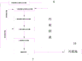
fig. 1 is a schematic structural view of the present invention;
FIG. 2 is a schematic flow diagram of an MBR system in accordance with the present invention.
The fifth embodiment is as follows:
the invention will be further explained and explained with reference to the following description of the drawings:
referring to fig. 1-2, a treatment device for zero discharge of landfill leachate in a waste incineration power station is characterized in that according to the treatment sequence of zero discharge of the landfill leachate in the waste incineration power station, a mechanical grating 1, a grit chamber 2, an adjusting tank 3, an anaerobic treatment system 4, an MBR system, a nanofiltration system 8, a reverse osmosis system 9 and a water production tank 10 are sequentially connected by pipelines, the anaerobic treatment system 4 adopts a UBF moderate temperature anaerobic reactor, a sewage discharge pipeline is arranged at the bottom of the UBF moderate temperature anaerobic reactor, one end of the sewage discharge pipeline is connected with a sludge tank, and the other end of the anaerobic treatment system 4 is connected with a biogas collection tank 5; the grit chamber is connected with the sludge tank, the MBR system consists of a two-stage nitrification and denitrification reactor 6 and an external ultrafiltration membrane component 7, the anaerobic treatment system 4 is connected with the two-stage nitrification and denitrification reactor 6, and the two-stage nitrification and denitrification reactor 6 is connected with the sludge tank; the device also comprises a concentrated solution decrement system 12 which is connected and arranged, wherein the concentrated solution decrement system 12 adopts a combined mode of coagulating sedimentation and an internal circulation machine to carry out the decrement treatment of the concentrated solution; the concentrated solution decrement system 12 is respectively connected with the nanofiltration system 8 and the reverse osmosis system 9, and the concentrated solution decrement system 12 is connected with the concentrated solution tank 15 and is used for enabling the concentrated solution after the decrement treatment to flow into the concentrated solution tank for back spraying of the concentrated solution; this device still includes sludge treatment system, and sludge treatment system comprises sludge dewatering system 13 and sludge chemical feeding system 14, wherein: the sludge dewatering system 13 comprises a sludge lift pump, a centrifugal dewatering machine, a shaftless screw conveyor and a sludge clear liquid lift pump, one end of the sludge clear liquid lift pump is connected with the two-stage nitrification and denitrification reactor 6, the other end of the sludge clear liquid lift pump is connected with the centrifugal dewatering machine, one end of the centrifugal dewatering machine is connected with the shaftless screw conveyor, the shaftless screw conveyor is connected with the incineration treatment system 16, a sludge pool is connected with the sludge lift pump, dewatered mud cakes are conveyed into the boiler incineration treatment system 16 through the shaftless screw conveyor, and the generated clear liquid flows back to the denitrification reactor along a pipeline through the sludge clear liquid lift pump; the sludge dosing system 14 is connected with the centrifugal dehydrator; the number of membrane components of the nanofiltration system 8 is 48, the number of membrane components of the reverse osmosis system 9 is 36, and the membrane components of the nanofiltration system 8 and the reverse osmosis system 9 both adopt DOW spiral roll type polyamide composite membrane two-stage nitrification-denitrification reactor 6 and sequentially comprise a first-stage preposed denitrification reactor, a first-stage preposed nitrification reactor, a second-stage denitrification reactor and a second-stage nitrification reactor.
The following concrete explanation the utility model discloses an operating method for refuse incineration power plant medium landfill leachate zero release's processing system, including following step:
①, preprocessing, namely, adopting a mechanical grid, a grit chamber and an adjusting tank as preprocessing devices;
firstly, removing floating materials of percolate of an incineration plant through a mechanical grid, then flowing into a grit chamber to remove larger silt in the percolate, finally flowing into an adjusting tank, finishing the reserved treatment, reducing the SS content in raw water by the above operation, wherein the SS removal rate in the raw water is up to more than 50%, and simultaneously, the COD and the BOD5 content are also reduced;
② anaerobic treatment:
the leachate after pretreatment enters an anaerobic reactor through a regulating reservoir lifting pump, and the leachate enables organic pollutants to be insulated through the action of anaerobic microorganismsMost of the biogas is decomposed into micromolecular substances such as methane gas, water, ammonia nitrogen, hydrogen sulfide, phosphate, inorganic salt and the like, the biogas generated by the anaerobic reactor is conveyed into a biogas collecting tank through a pipeline, and the biogas is sprayed back into the incinerator after being subjected to subsequent treatment; the sludge in the anaerobic reactor is periodically discharged into a sludge tank through a pipeline, and attention is paid to that: the debugging of the UBF anaerobic reactor is the key point of the debugging of an anaerobic system, and as the growth speed of anaerobic sludge is slow, leachate enters the reactor in batches and runs intermittently so as to improve the metabolic efficiency and the growth speed of the reactor; the debugging process finds that when the temperature of the reactor is controlled to be 30-35 ℃, the treatment effect of the percolate is optimal, so that the reaction temperature of the reactor is ensured by adopting a boiler waste heat steam heating method in winter; the biogas generated by the anaerobic reactor is treated and then sprayed back to the incinerator, thereby improving the economic and environmental benefits of the anaerobic reactor, and COD and BOD in the leachate are adjusted by the anaerobic system5The SS content is obviously reduced, wherein the COD removal rate can reach 86 percent, and the BOD5The removal rate can reach 93 percent, and the removal rate of SS can reach 69 percent;
③ MBR system comprises a primary preposed denitrification reactor, a primary preposed nitrification reactor, a secondary denitrification reactor and a secondary nitrification reactor, wherein the primary preposed denitrification reactor, the secondary nitrification reactor and the secondary nitrification reactor are sequentially connected, a submerged stirring device is arranged in a denitrification tank, sludge concentrated by an MBR membrane component after anaerobic treatment flows back to the denitrification reactor, secondary nitrification product water flows back to an ultrafiltration system and is subjected to mud-water separation by an external tubular ultrafiltration membrane (TMBR), product water enters an ultrafiltration product water tank, residual sludge enters the sludge tank, sludge cake dehydrated by a sludge dehydration system is delivered to a boiler for incineration treatment, and the generated clear liquid flows back to the denitrification reactor through a pipeline, wherein the secondary nitrification reactor comprises the primary denitrification reactor, the primary nitrification reactor, the secondary denitrification reactor and the secondary nitrification reactor, the primary denitrification reactor comprises two denitrification reactors, and the effective volume of 960m3The retention time in water is 2d, and an underwater stirring mode is adopted; the first-stage nitrification tank has two effective volumesProduct of 2880m3The hydraulic retention time is 6d, a jet aeration mode is adopted, and the aeration rate is 165m3Min; two secondary denitrification pools with the effective volume of 424m3The hydraulic retention time is 21h, and an underwater stirring mode is adopted; the two secondary nitrification tanks have the effective volume of 360m3The hydraulic retention time is 18h, a jet aeration mode is adopted, and the aeration rate is 10m3Min; nitrifying liquid of the first-stage nitrifying reactor flows back into the first-stage denitrifying reactor, and nitrifying liquid of the second-stage nitrifying reactor flows back into the second-stage denitrifying reactor;
in the debugging process, the proper pH value in the denitrification process is determined to be 6.5-7.5; as the denitrification process can generate alkalinity and the pH value can be continuously improved along with the accumulation of the alkalinity, a hydrochloric acid system is added according to actual conditions to control the pH value. The nitration process is suitable for the pH value of 7-8, and the pH value is reduced by consuming alkalinity in the nitration process, so the pH value is controlled by adding sodium bicarbonate according to the actual condition. Meanwhile, adding a carbon source into the secondary denitrification tank to ensure the carbon source required by denitrification, and removing redundant carbon sources after entering the secondary nitrification tank; by debugging the ultrafiltration system, the SS in the water is obviously reduced; the debugging result of the system shows that the COD content can be reduced to below 750mg/L, and the removal rate reaches more than 92 percent; BOD5And NH3The N content can be reduced to below 10mg/L, and the removal rate of the N content and the N content can reach more than 99.6 percent; the SS content can be reduced to below 30mg/L, the removal rate can reach more than 99 percent, and the treatment effect is better.
④ nanofiltration and reverse osmosis system:
the COD content of the produced water can be reduced to be below 100mg/L by debugging the wastewater through a nanofiltration system, and the removal rate of the COD can reach more than 87%; the COD content of the produced water of the wastewater can be reduced to below 60mg/L by debugging the reverse osmosis system, the removal rate of the COD can reach more than 40 percent, and the water quality standard is met.
⑤ concentration and reduction system:
concentrated solution generated by the nanofiltration system and the reverse osmosis system is conveyed to a concentrated solution reduction system through a pipeline, and 60% of divalent salt ions and part of refractory substances in the concentrated solution are removed through debugging of a coagulating sedimentation system; by debugging the membrane advanced treatment internal circulation system, the water yield is more than or equal to 55 percent, the yield of the concentrated solution accounts for less than or equal to 15 percent of the percentage table of the total treatment scale of the percolate system, and the effect is obvious; meanwhile, the concentrated solution is sprayed back to the boiler for reuse, and zero discharge of wastewater is realized.
⑥ the sludge treatment system works in a centrifugal dehydration mode;
the sludge tank moves sludge from the sludge tank to a sludge dewatering system through a sludge lifting pump, and meanwhile, a sludge dosing system adds drugs into the sludge dewatering system, when the configured concentration of a flocculating agent (PAM) is 1-3 per mill, and the adding amount is 0.13-0.16 m3/m3The dewatering effect is best when the sludge is wet, the dewatering rate reaches about 85 percent, the dewatered sludge cake is sent to a boiler incineration treatment system, and clear liquid is sent to a denitrification tank for treatment.
The utility model discloses a debugging of filtration liquid system in the above-mentioned embodiment, its each section goes out water quality of water and reaches the designing requirement to final play water quality of water accords with national relevant standard, and its each system goes out water quality of water and sees table 2.
TABLE 2 quality of leachate effluent from each system

The utility model discloses a leachate that pretreatment systems, medium temperature anaerobic treatment system, MBR system (contain and nitrify denitrification and external ultrafiltration), receive filtration system, reverse osmosis system, sludge treatment system, concentrate processing system's processing technology and handle this waste incineration power station realizes the waste water zero release of whole factory, has reduced environmental pollution, has practiced thrift the water resource.
Claims (5)
1. A treatment device for zero discharge of garbage percolate in a garbage incineration power station is characterized in that; the device is characterized in that according to the treatment sequence of zero emission of waste penetrating fluid in a waste incineration power station, a mechanical grid (1), a grit chamber (2), an adjusting tank (3), an anaerobic treatment system (4), an MBR system, a nanofiltration system (8), a reverse osmosis system (9) and a water production tank (10) are sequentially connected through pipelines, the anaerobic treatment system (4) adopts a medium-temperature anaerobic reactor, a sewage discharge pipeline is arranged at the bottom of the medium-temperature anaerobic reactor, one end of the sewage discharge pipeline is connected with a sludge tank (10), and the other end of the anaerobic treatment system (4) is connected with a methane collection tank (5); the grit chamber (2) is connected with the sludge impoundment, the MBR system comprises a two-stage nitrification and denitrification reactor (6) and an external ultrafiltration membrane component (7), the anaerobic treatment system (4) is connected with the two-stage nitrification and denitrification reactor (6), and the two-stage nitrification and denitrification reactor (6) is connected with the sludge impoundment (10).
2. The treatment plant according to claim 1 for zero discharge of landfill leachate in waste incineration plants, characterized in that: the device also comprises a concentrated solution decrement system (12) which is connected and arranged, wherein the concentrated solution decrement system (12) adopts a combined mode of coagulating sedimentation and an internal circulation machine to carry out the decrement treatment of the concentrated solution; the concentrated solution decrement system (12) is connected with the nanofiltration system (8) and the reverse osmosis system (9), and the concentrated solution decrement system (12) is connected with the concentrated solution tank (15) and is used for enabling the concentrated solution after decrement treatment to flow into the concentrated solution tank for back spraying of the concentrated solution.
3. The treatment plant according to claim 1 for zero discharge of landfill leachate in waste incineration plants, characterized in that: the device is still including connecting the sludge treatment system that sets up, sludge treatment system constitute by sludge dewatering system (13) and mud medicine system (14), sludge dewatering system (13) comprise mud elevator pump, centrifugal dehydration machine, shaftless screw conveyer, mud clear solution elevator pump, the one end and the doublestage of mud clear solution elevator pump are nitrify denitrification reactor (6) and are connected, the other end and the centrifugal dehydration machine of mud clear solution elevator pump are connected, centrifugal dehydration machine's one end and shaftless screw conveyer are connected, shaftless screw conveyer is connected with incineration disposal system (16), the sludge impoundment is connected with the mud elevator pump, mud medicine system (14) are connected with centrifugal dehydration machine.
4. The treatment plant according to claim 1 for zero discharge of landfill leachate in waste incineration plants, characterized in that: the number of membrane components of the nanofiltration system (8) is 48, the number of membrane components of the reverse osmosis system (9) is 36, and the membrane components of the nanofiltration system (8) and the reverse osmosis system (9) both adopt DOW spiral roll type polyamide composite membranes.
5. The treatment plant according to claim 1 for zero discharge of landfill leachate in waste incineration plants, characterized in that: the two-stage nitrification and denitrification reactor (6) is sequentially composed of a primary preposed denitrification reactor, a primary preposed nitrification reactor, a secondary denitrification reactor and a secondary nitrification reactor.
Priority Applications (1)
| Application Number | Priority Date | Filing Date | Title |
|---|---|---|---|
| CN201920912676.6U CN210736456U (en) | 2019-06-18 | 2019-06-18 | Treatment device for zero discharge of garbage leachate in garbage incineration power station |
Applications Claiming Priority (1)
| Application Number | Priority Date | Filing Date | Title |
|---|---|---|---|
| CN201920912676.6U CN210736456U (en) | 2019-06-18 | 2019-06-18 | Treatment device for zero discharge of garbage leachate in garbage incineration power station |
Publications (1)
| Publication Number | Publication Date |
|---|---|
| CN210736456U true CN210736456U (en) | 2020-06-12 |
Family
ID=70984961
Family Applications (1)
| Application Number | Title | Priority Date | Filing Date |
|---|---|---|---|
| CN201920912676.6U Active CN210736456U (en) | 2019-06-18 | 2019-06-18 | Treatment device for zero discharge of garbage leachate in garbage incineration power station |
Country Status (1)
| Country | Link |
|---|---|
| CN (1) | CN210736456U (en) |
Cited By (3)
| Publication number | Priority date | Publication date | Assignee | Title |
|---|---|---|---|---|
| CN110316905A (en) * | 2019-06-18 | 2019-10-11 | 中国电建集团河南工程有限公司 | Processing system for landfill leachate zero-emission in garbage incineration power plant |
| CN112624503A (en) * | 2020-12-16 | 2021-04-09 | 北京高安屯垃圾焚烧有限公司 | Landfill leachate anaerobic treatment device and treatment method |
| CN112642565A (en) * | 2020-12-02 | 2021-04-13 | 北京建筑大学 | System and method for full resource treatment of town garbage |
-
2019
- 2019-06-18 CN CN201920912676.6U patent/CN210736456U/en active Active
Cited By (3)
| Publication number | Priority date | Publication date | Assignee | Title |
|---|---|---|---|---|
| CN110316905A (en) * | 2019-06-18 | 2019-10-11 | 中国电建集团河南工程有限公司 | Processing system for landfill leachate zero-emission in garbage incineration power plant |
| CN112642565A (en) * | 2020-12-02 | 2021-04-13 | 北京建筑大学 | System and method for full resource treatment of town garbage |
| CN112624503A (en) * | 2020-12-16 | 2021-04-09 | 北京高安屯垃圾焚烧有限公司 | Landfill leachate anaerobic treatment device and treatment method |
Similar Documents
| Publication | Publication Date | Title |
|---|---|---|
| CN101234836B (en) | Garbage percolate treatment technique | |
| CN110316905A (en) | Processing system for landfill leachate zero-emission in garbage incineration power plant | |
| CN210736456U (en) | Treatment device for zero discharge of garbage leachate in garbage incineration power station | |
| CN102603128A (en) | Method for advanced treatment and recycling of landfill leachate | |
| CN102464420A (en) | Sewage physical-chemical treatment method | |
| CN108285240A (en) | Meet the municipal solid waste incinerator leachate processing method of cooling tower recycle-water requirement | |
| CN111253013A (en) | Method and device for treating landfill leachate membrane concentrated solution | |
| CN205347102U (en) | Degree of depth processing system of direct liquefaction of coal sewage | |
| CN107151082B (en) | Zero-discharge treatment system and method for DMF (dimethyl formamide) -containing wastewater | |
| CN112441701B (en) | Shale gas flowback fluid efficient treatment, reuse and zero emission method and system | |
| CN212293240U (en) | Zero-emission treatment system for leachate of waste incineration plant | |
| CN109502911A (en) | A kind of sewage water treatment method | |
| CN108264193A (en) | A kind of processing method for improving municipal solid waste incinerator percolate water yield | |
| CN202148211U (en) | Treatment device of concentrated water generated by nano filtration and reverse osmosis membrane in garbage percolate treatment | |
| CN202785898U (en) | Device for treating and recycling wastewater from processing of coal tar | |
| CN210340611U (en) | Combined treatment system for complex wastewater of drilling and completion of oil and gas field | |
| CN114835347A (en) | System for recovering sewage energy and resource and reducing greenhouse gas emission | |
| CN211521950U (en) | System for reducing concentration of pollutants in steel comprehensive wastewater | |
| CN211712895U (en) | Leachate treatment system for waste incineration power plant | |
| CN211445406U (en) | Landfill leachate treatment device | |
| CN114436467A (en) | Integrated device and method for treating leachate of garbage transfer station | |
| CN211284073U (en) | Landfill leachate treatment facility | |
| CN217103497U (en) | New energy is sewage treatment plant in coordination | |
| CN221254298U (en) | Photoelectric material waste water recycling treatment system | |
| CN213803262U (en) | Leachate emergency treatment system for refuse incineration plant |
Legal Events
| Date | Code | Title | Description |
|---|---|---|---|
| GR01 | Patent grant | ||
| GR01 | Patent grant |