CN210715753U - Novel right-angle speed reducer - Google Patents
Novel right-angle speed reducer Download PDFInfo
- Publication number
- CN210715753U CN210715753U CN201921518976.2U CN201921518976U CN210715753U CN 210715753 U CN210715753 U CN 210715753U CN 201921518976 U CN201921518976 U CN 201921518976U CN 210715753 U CN210715753 U CN 210715753U
- Authority
- CN
- China
- Prior art keywords
- input shaft
- box
- output shaft
- gear
- ball bearing
- Prior art date
- Legal status (The legal status is an assumption and is not a legal conclusion. Google has not performed a legal analysis and makes no representation as to the accuracy of the status listed.)
- Active
Links
Images


Landscapes
- Gear Transmission (AREA)
Abstract
The utility model discloses a novel right angle type speed reducer, the power distribution box comprises a box body, be equipped with in the box along the input shaft of vertical setting and along the output shaft of horizontal setting, install the toothed disc in the circumference of output shaft, the face gear has on the terminal surface of toothed disc, the upper end of input shaft has the input shaft gear, the input shaft gear forms face gear drive structure with the perpendicular meshing transmission of face gear, the one end of output shaft stretches out in the box, and the other end passes through adjusting screw and is connected with the box, the output shaft stretches out to be connected through adjusting nut between the one end of box and the box, adjusting screw and adjusting nut adjust the meshing clearance of toothed disc and input shaft. In this way, the utility model discloses right angle type speed reducer can improve the whole transmission precision of speed reducer, simple structure, simple to operate, low in production cost.
Description
Technical Field
The utility model relates to a speed reducer field especially relates to a novel right angle type speed reducer.
Background
The right-angle reducer is a machine type with an input shaft and an output shaft having an intersection angle of 90 degrees. In recent years, a large number of right-angle speed reducers appear in industrial production lines and a large number of devices introduced from abroad, because the right-angle speed reducers can enable the industrial production lines or some main machines to be more compact in matching and occupy the space as small as possible. The right-angle speed reducer technology comes from abroad, and the right-angle speed reducer adopts a transmission mode of two-stage speed reduction of a cylindrical involute gear and a worm and worm gear. In addition, there are involute gears and bevel gears. The first structure has the defects that the high-speed gear transmission has higher noise, the low-speed worm and worm gear transmission has lower efficiency and higher temperature, and if the low-speed gear is the ring surface worm transmission, the manufacturing process is complex, a special high-precision machining machine tool and a complex machining process are needed, so that the manufacturing cost is greatly increased; the second structure has the disadvantages of loud noise, troublesome assembly and processing, and less extensive application than the former.
Disclosure of Invention
The utility model discloses the main technical problem who solves provides a novel right angle type speed reducer, can improve the whole transmission precision of speed reducer, simple structure, simple to operate, low in production cost.
In order to solve the technical problem, the utility model discloses a technical scheme be: the utility model provides a novel right angle type speed reducer, the power distribution box comprises a box body, be equipped with along the input shaft of vertical setting and along the output shaft of horizontal setting in the box, install the toothed disc in the circumference of output shaft, the face gear has on the terminal surface of toothed disc, the upper end of input shaft has the input shaft gear, the input shaft gear forms a gear transmission structure with the perpendicular meshing transmission of face gear, the both ends of output shaft stretch out in the box and be used for output power, connect through adjusting nut between the both ends of output shaft and the box, adjusting nut adjusts the meshing clearance of toothed disc and input shaft.
In a preferred embodiment of the present invention, the output shaft and the gear plate are tightly connected by a locking screw.
In a preferred embodiment of the present invention, the output shaft is radially connected to a first deep groove ball bearing, the first deep groove ball bearing is installed inside the box, and the gear plate is located inside the first deep groove ball bearing.
In a preferred embodiment of the present invention, a connecting flange is installed below the housing, and the input shaft is installed in the connecting flange and has an upper end extending into the housing.
In a preferred embodiment of the invention, the input shaft is radially connected to a second deep groove ball bearing, which is mounted on the connecting flange.
In a preferred embodiment of the present invention, a transition flange is mounted on the lower end of the connecting flange, and the lower end of the input shaft is located in the transition flange and is connected with the servo motor through a clamping clamp.
In a preferred embodiment of the present invention, the box body is provided with a skeleton oil seal at the left and right ends, and the skeleton oil seal is located outside the adjusting nut.
The utility model has the advantages that: the utility model discloses right angle type speed reducer can improve the whole transmission precision of speed reducer, simple structure, simple to operate, low in production cost.
Drawings
In order to more clearly illustrate the technical solutions of the embodiments of the present invention, the drawings used in the description of the embodiments are briefly introduced below, and it is obvious that the drawings in the following description are only some embodiments of the present invention, and for those skilled in the art, other drawings can be obtained without inventive work, wherein:
fig. 1 is a schematic structural diagram of a preferred embodiment of the right-angle reducer of the present invention;
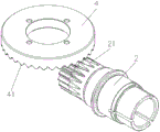
FIG. 2 is a schematic view of a portion of the structure of FIG. 1;
FIG. 3 is a front view of FIG. 2;
FIG. 4 is an external view of the structure of FIG. 1;
the parts in the drawings are numbered as follows: 1. the device comprises a box body, 2, an input shaft, 21, an input shaft gear, 3, an output shaft, 4, a gear disc, 41, a face gear, 5, a framework oil seal, 6, an adjusting nut, 7, a locking screw, 8, a first deep groove ball bearing, 9, a connecting flange, 10, a second deep groove ball bearing, 11, a transition flange, 12 and a clamping clamp.
Detailed Description
The technical solutions in the embodiments of the present invention will be described clearly and completely below, and it should be apparent that the described embodiments are only some embodiments of the present invention, but not all embodiments. Based on the embodiments in the present invention, all other embodiments obtained by a person skilled in the art without creative efforts belong to the protection scope of the present invention.
Please refer to fig. 1, a novel right-angle speed reducer, including box 1, be equipped with in the box 1 along the vertical input shaft 2 that sets up and along the output shaft 3 of horizontal setting, install toothed disc 4 in the circumference of output shaft 3, face gear 41 has on the terminal surface of toothed disc 4, input shaft gear 21 has in the upper end of input shaft 2, input shaft gear 21 forms face gear drive structure with face gear 41 vertical meshing transmission, the both ends of output shaft 3 stretch out in box 1 and are used for output power, connect through adjusting nut 6 between the both ends of output shaft 3 and the box 1, adjusting nut 6 adjusts the meshing clearance of toothed disc 4 and input shaft 2. The structure has the assembly freedom degree in the axial direction, is insensitive to assembly errors, is easy for tooth profile trimming and backlash adjustment, and has higher contact rate.
In addition, the output shaft 3 and the gear plate 4 are tightly connected through a locking screw 7.
In addition, the output shaft 3 is radially connected with the first deep groove ball bearing 8, the first deep groove ball bearing 8 is installed on the inner side of the box body 1, and the gear plate 1 is located on the inner side of the first deep groove ball bearing 8.
In addition, a connecting flange 9 is installed below the box body 1, the input shaft 2 is installed in the connecting flange 9, and the upper end of the input shaft extends into the box body 1.
In addition, the input shaft 2 is radially connected to a second deep groove ball bearing 10, and the second deep groove ball bearing 10 is mounted on the connecting flange 9.
In addition, a transition flange 11 is installed at the lower end of the connecting flange 9, the lower end of the input shaft is located in the transition flange and is connected with the servo motor in a clamping mode through a clamping clamp 12, and power is input through the servo motor.
In addition, framework oil seals 5 are installed at the left end and the right end of the box body 1, and the framework oil seals 5 are located on the outer sides of the adjusting nuts 6.
The utility model discloses the concrete theory of operation of right angle type speed reducer is as follows: the input shaft 2 is connected with the servo motor through the clamping clamp 12, the servo motor is started to drive the input shaft 2 to rotate, the input shaft gear 21 at the upper end of the input shaft 2 transmits power to the gear disc 4 through the face gear 41, the gear disc 4 drives the shaft output shaft 3 to rotate, and the power is output outwards through the output shaft 3.
Be different from prior art, the utility model discloses right angle type speed reducer can improve the whole transmission precision of speed reducer, simple structure, simple to operate, low in production cost.
The above only is the embodiment of the present invention, not limiting the patent scope of the present invention, all of which utilize the equivalent structure or equivalent flow transformation made by the content of the specification of the present invention, or directly or indirectly applied to other related technical fields, all included in the same way in the patent protection scope of the present invention.
Claims (7)
1. The utility model provides a novel right angle type speed reducer, the power distribution box comprises a box body, be equipped with in the box along the input shaft of vertical setting and along the output shaft of horizontal setting, its characterized in that, install the toothed disc in the circumference of output shaft, the face gear has on the terminal surface of toothed disc, the upper end of input shaft has the input shaft gear, the input shaft gear forms face gear transmission structure with the perpendicular meshing transmission of face gear, the both ends of output shaft stretch out in the box and be used for output power, connect through adjusting nut between the both ends of output shaft and the box, adjusting nut adjusts the meshing clearance of toothed disc and input shaft.
2. The right-angle reducer according to claim 1, wherein the output shaft and the gear plate are fastened and connected through a locking screw.
3. The novel right-angle reducer according to claim 2, wherein the output shaft is radially connected with a first deep groove ball bearing, the first deep groove ball bearing is mounted inside the box body, and the gear plate is located inside the first deep groove ball bearing.
4. The right-angle reducer according to claim 1, wherein a connecting flange is mounted below the box body, the input shaft is mounted in the connecting flange, and the upper end of the input shaft extends into the box body.
5. The novel right-angle reducer according to claim 4, wherein the input shaft is radially connected with a second deep groove ball bearing, and the second deep groove ball bearing is mounted on the connecting flange.
6. The right-angle reducer according to claim 5, wherein a transition flange is mounted at a lower end of the connecting flange, and a lower end of the input shaft is located in the transition flange and is in clamping connection with the servo motor through a clamping clamp.
7. The right-angle reducer according to claim 1, wherein framework oil seals are mounted at the left end and the right end of the box body, and the framework oil seals are located on the outer side of the adjusting nut.
Priority Applications (1)
| Application Number | Priority Date | Filing Date | Title |
|---|---|---|---|
| CN201921518976.2U CN210715753U (en) | 2019-09-12 | 2019-09-12 | Novel right-angle speed reducer |
Applications Claiming Priority (1)
| Application Number | Priority Date | Filing Date | Title |
|---|---|---|---|
| CN201921518976.2U CN210715753U (en) | 2019-09-12 | 2019-09-12 | Novel right-angle speed reducer |
Publications (1)
| Publication Number | Publication Date |
|---|---|
| CN210715753U true CN210715753U (en) | 2020-06-09 |
Family
ID=70931875
Family Applications (1)
| Application Number | Title | Priority Date | Filing Date |
|---|---|---|---|
| CN201921518976.2U Active CN210715753U (en) | 2019-09-12 | 2019-09-12 | Novel right-angle speed reducer |
Country Status (1)
| Country | Link |
|---|---|
| CN (1) | CN210715753U (en) |
Cited By (1)
| Publication number | Priority date | Publication date | Assignee | Title |
|---|---|---|---|---|
| CN110630691A (en) * | 2019-09-12 | 2019-12-31 | 无锡市恒翼通机械有限公司 | Novel right-angle speed reducer |
-
2019
- 2019-09-12 CN CN201921518976.2U patent/CN210715753U/en active Active
Cited By (1)
| Publication number | Priority date | Publication date | Assignee | Title |
|---|---|---|---|---|
| CN110630691A (en) * | 2019-09-12 | 2019-12-31 | 无锡市恒翼通机械有限公司 | Novel right-angle speed reducer |
Similar Documents
| Publication | Publication Date | Title |
|---|---|---|
| CN210715754U (en) | Right-angle speed reducer | |
| CN110630692A (en) | Right-angle speed reducer | |
| CN210715753U (en) | Novel right-angle speed reducer | |
| CN103335064A (en) | Automatic clearance-removing double-worm speed reducer | |
| CN204094480U (en) | The coding turntable of Changeable Lead Worm Wheel System | |
| CN201970133U (en) | Anti-backlash reduction box | |
| CN110630691A (en) | Novel right-angle speed reducer | |
| CN206754289U (en) | Double servo worm-gear speed reducers and lathe | |
| CN104675980A (en) | Automatic plane-enveloping internal-meshing worm and worm gear clearance elimination device | |
| CN108775383B (en) | Adjustable precise planetary gear reducer | |
| CN204437188U (en) | A kind of elevator worm and gear speed-reduction apparatus | |
| CN203395105U (en) | Double worm reducer capable of automatically eliminating clearance | |
| CN103148202B (en) | Large-scale high-precision rotating disk is without back clearance drive method | |
| CN110925409B (en) | Elastic anti-backlash reducer for planetary gear | |
| CN204387290U (en) | A kind of planar envelope internal messing worm and worm gear automatic gap eliminating device | |
| CN115126838A (en) | Double-freedom-degree mechanical arm with adjustable backlash based on conical worm transmission | |
| CN112571086A (en) | B-axis rotary worktable structure | |
| CN215831120U (en) | Worm gear backlash adjusting device | |
| CN202367510U (en) | Tool inclination and tool rotation mechanism applied to numerical control gear milling machine for extended epicycloid bevel gears | |
| CN111677840A (en) | High-working-performance worm and gear speed reducer | |
| CN201455457U (en) | Indexing mechanism for heavy-duty spiral bevel gear shaving machine | |
| CN206500639U (en) | Machine tool chief axis module | |
| CN204828626U (en) | Structure of numerical control lathe screw actuation gear box | |
| CN202438752U (en) | Worm gear pair backlash eliminating device for work-piece main shaft of gear milling machine | |
| CN103406601A (en) | Vertical-type five-shaft linkage gear hobbing machine tool |
Legal Events
| Date | Code | Title | Description |
|---|---|---|---|
| GR01 | Patent grant | ||
| GR01 | Patent grant |