CN210576336U - Improve heat radiation structure of high-efficient energy storage of new forms of energy battery - Google Patents
Improve heat radiation structure of high-efficient energy storage of new forms of energy battery Download PDFInfo
- Publication number
- CN210576336U CN210576336U CN201922044529.4U CN201922044529U CN210576336U CN 210576336 U CN210576336 U CN 210576336U CN 201922044529 U CN201922044529 U CN 201922044529U CN 210576336 U CN210576336 U CN 210576336U
- Authority
- CN
- China
- Prior art keywords
- heat dissipation
- shell
- fixedly connected
- battery
- cooling box
- Prior art date
- Legal status (The legal status is an assumption and is not a legal conclusion. Google has not performed a legal analysis and makes no representation as to the accuracy of the status listed.)
- Active
Links
Images


Classifications
-
- Y—GENERAL TAGGING OF NEW TECHNOLOGICAL DEVELOPMENTS; GENERAL TAGGING OF CROSS-SECTIONAL TECHNOLOGIES SPANNING OVER SEVERAL SECTIONS OF THE IPC; TECHNICAL SUBJECTS COVERED BY FORMER USPC CROSS-REFERENCE ART COLLECTIONS [XRACs] AND DIGESTS
- Y02—TECHNOLOGIES OR APPLICATIONS FOR MITIGATION OR ADAPTATION AGAINST CLIMATE CHANGE
- Y02E—REDUCTION OF GREENHOUSE GAS [GHG] EMISSIONS, RELATED TO ENERGY GENERATION, TRANSMISSION OR DISTRIBUTION
- Y02E60/00—Enabling technologies; Technologies with a potential or indirect contribution to GHG emissions mitigation
- Y02E60/10—Energy storage using batteries
Landscapes
- Secondary Cells (AREA)
Abstract
The utility model belongs to the technical field of new energy battery heat dissipation, in particular to a heat dissipation structure for improving the high-efficiency energy storage of a new energy battery, which comprises a shell, wherein the bottom of the shell is fixedly connected with a cooling box, and the inner wall of the cooling box is fixedly connected with a refrigerator; the utility model discloses, through the water pump work, can pass through the pipe-line transportation with the coolant liquid after the refrigerator refrigeration in the cooler bin to two circulating line in, realize carrying out cooling radiating purpose to the inside battery of casing, reach the water-cooling radiating effect, through setting up heat conduction silica gel gasket cooperation conducting strip, can conduct the inside heat of casing, the device adopts the cooler bin, the pipeline, a water pump, the circulating pipe, the flabellum, the conducting strip, first louvre and second louvre, two kinds of radiating mode of water-cooling and forced air cooling have been realized carrying out the battery, the radiating effect has been ensured greatly, the radiating efficiency is improved, whole device is rational in infrastructure, and easy operation, therefore, the clothes hanger is strong in practicability.
Description
Technical Field
The utility model belongs to the technical field of the new forms of energy battery heat dissipation, concretely relates to improve heat radiation structure of high-efficient energy storage of new forms of energy battery.
Background
The battery is a part of space of a cup, a groove or other containers or composite containers which are filled with electrolyte solution and metal electrodes to generate current, and can convert chemical energy into electric energy, and has a positive electrode and a negative electrode.
Along with the reinforcing of people's environmental protection consciousness and the popularity of environmental protection concept, new energy battery is by extensive application in a plurality of fields, but current new energy battery has the poor drawback of radiating effect, is unfavorable for the guarantee energy storage effect, and current radiating mode adopts the forced air cooling wind channel to dispel the heat mostly, and radiating mode is single, and the radiating efficiency is low.
SUMMERY OF THE UTILITY MODEL
To solve the problems set forth in the background art described above. The utility model provides an improve heat radiation structure of high-efficient energy storage of new forms of energy battery has the characteristics that the radiating effect is good and convenient to use.
In order to achieve the above object, the utility model provides a following technical scheme: a heat dissipation structure for improving efficient energy storage of a new energy battery comprises a shell, wherein a cooling box is fixedly connected to the bottom of the shell, a refrigerator is fixedly connected to the inner wall of the cooling box, a pipeline is fixedly connected to the side face of the cooling box, one end of the pipeline penetrates through the side face of the shell and is fixedly connected with a circulating pipe, a water pump is arranged on the pipeline and is fixedly connected to the side face of the shell, the two circulating pipes are respectively embedded in the front side and the rear side of the inner wall of the shell, the top ends and the bottom ends of the two circulating pipes are communicated through a connecting pipe, the bottom end of the circulating pipe penetrates through the shell and is positioned in the cooling box, a heat conduction silica gel gasket is fixedly connected to the inner wall of the shell, a cover plate is movably connected to the top of the shell through a hinge, the side face of the cover plate is fixedly connected with the, the battery is connected in the upper and lower two draw-in grooves in the joint, be provided with the conducting strip between the battery, conducting strip fixed connection is at shells inner wall, the second louvre has all been seted up to the front side and the rear side of casing, the downthehole fixedly connected with flabellum of second louvre, be provided with the second dust screen in the second louvre.
Preferably, a plurality of first heat dissipation holes are formed in the top of the cover plate, and first dust screens are arranged in the first heat dissipation holes.
Preferably, a water inlet is formed in the side face of the cooling box, and a sealing plug is arranged in the water inlet.
Preferably, a pipe sleeve is fixedly connected to a side surface of the shell, and the pipe sleeve is sleeved on the surface of the pipeline.
Preferably, a button switch is arranged on the front side of the cooling box and electrically connected with the water pump through a conducting wire.
Compared with the prior art, the beneficial effects of the utility model are that:
the utility model can convey the cooling liquid refrigerated by the refrigerator in the cooling box into two circulating pipelines through the pipelines by the operation of the water pump, thereby realizing the purpose of cooling and radiating the battery in the shell, achieving the effect of water-cooling and radiating, conducting the heat in the shell by arranging the heat-conducting silica gel gasket and the heat-conducting fin, further facilitating the realization of the purpose of heat-conducting and radiating through the first radiating hole, realizing the radiating purpose by arranging the second radiating hole for matching with the fan blade under the driving of external wind power, forming convection front and back and enhancing the radiating effect, the device adopts the cooling box, the pipelines, the water pump, the circulating pipelines, the fan blades, the heat-conducting fin, the first radiating hole and the second radiating hole, realizing two radiating modes of water-cooling and air-cooling to the battery, greatly ensuring the radiating effect, improving the radiating efficiency, and having reasonable structure, the operation is simple, and the practicability is strong.
Drawings
The accompanying drawings are included to provide a further understanding of the invention, and are incorporated in and constitute a part of this specification, illustrate embodiments of the invention, and together with the description serve to explain the invention and not to limit the invention. In the drawings:
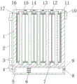
fig. 1 is a schematic structural view of a front view section of the present invention;
fig. 2 is a schematic structural diagram of a middle front view section of the present invention;
FIG. 3 is a front view of the present invention;
in the figure: 1. a housing; 2. a pipeline; 3. pipe sleeve; 4. a water pump; 5. a cooling tank; 6. a refrigerator; 7. A heat conductive sheet; 8. a sealing plug; 9. a water inlet; 10. locking; 11. a heat-conducting silica gel gasket; 12. a first dust screen; 13. a first heat dissipation hole; 14. a battery; 15. a card slot; 16. a cover plate; 17. a hinge; 18. A circulation pipe; 19. a connecting pipe; 20. a push button switch; 21. a second dust screen; 22. a second heat dissipation hole; 23. a fan blade.
Detailed Description
The technical solutions in the embodiments of the present invention will be described clearly and completely with reference to the accompanying drawings in the embodiments of the present invention, and it is obvious that the described embodiments are only some embodiments of the present invention, not all embodiments. Based on the embodiments in the present invention, all other embodiments obtained by a person skilled in the art without creative work belong to the protection scope of the present invention.
Examples
Referring to fig. 1-3, the present invention provides the following technical solutions: a heat dissipation structure for improving the high-efficiency energy storage of a new energy battery comprises a shell 1, wherein a cooling box 5 is fixedly connected to the bottom of the shell 1, a refrigerator 6 is fixedly connected to the inner wall of the cooling box 5, a pipeline 2 is fixedly connected to the side surface of the cooling box 5, one end of the pipeline 2 penetrates through the side surface of the shell 1 and is fixedly connected with a circulating pipe 18, a water pump 4 is arranged on the pipeline 2, the water pump 4 works, cooling liquid cooled by the refrigerator 6 in the cooling box 5 can be conveyed into the two circulating pipes 18 through the pipeline 2, the purpose of cooling and dissipating heat of a battery 14 in the shell 1 is achieved, the water cooling and heat dissipation effect is achieved, the water pump 4 is fixedly connected to the side surface of the shell 1, the circulating pipes 18 are two in number and are respectively embedded in the front side and the rear side of the inner wall of the shell 1, and the top ends and the, the bottom end of the circulating pipe 18 penetrates through the shell 1 and is positioned in the cooling box 5, the heat in the shell 1 can be conducted by arranging the heat-conducting silica gel gasket 11 to be matched with the heat-conducting sheet 7, so that the heat-conducting and heat-dissipating purposes can be realized through the first heat-dissipating holes 13, the inner wall of the shell 1 is fixedly connected with the heat-conducting silica gel gasket 11, the top of the shell 1 is movably connected with the cover plate 16 through the hinge 17, the side surface of the cover plate 16 is fixedly connected with the shell 1 through the lock catch 10, the bottom of the inner wall of the shell 1 and the bottom of the cover plate 16 are both provided with a plurality of clamping grooves 15, the batteries 14 are conveniently stored and fixed by arranging the cover plate 16 and the clamping grooves 15, the batteries 14 can be taken out by opening the cover plate 16, the batteries 14 are clamped in the upper clamping groove 15 and the lower, second louvre 22 has all been seted up to the front side and the rear side of casing 1, fixedly connected with flabellum 23 in the second louvre 22, be provided with second dust screen 21 in the second louvre 22, through setting up second louvre 22, be used for cooperating flabellum 23 to realize the heat dissipation purpose under the drive of external wind-force, form the convection current around, reinforcing radiating effect, the device adopts cooler bin 5, pipeline 2, water pump 4, circulating pipe 18, flabellum 23, conducting strip 7, first louvre 13 and second louvre 22, two kinds of radiating modes of having realized carrying out water cooling and forced air cooling to battery 14, the radiating effect has been ensured greatly, and the radiating efficiency is improved, and whole device is rational in infrastructure, and easy operation, the practicality is strong.
Specifically, a plurality of first heat dissipation holes 13 are formed in the top of the cover plate 16, first dust screens 12 are arranged in the first heat dissipation holes 13, and the probability of dust entering can be reduced while heat dissipation is achieved by arranging the first heat dissipation holes 13 and the first dust screens 12.
Specifically, a water inlet 9 is formed in the side surface of the cooling box 5, and a sealing plug 8 is arranged in the water inlet 9.
Specifically, the side face of the shell 1 is fixedly connected with the pipe sleeve 3, the pipe sleeve 3 is sleeved on the surface of the pipeline 2, and the pipe sleeve 3 is arranged, so that the pipeline 2 can be supported and fixed.
Specifically, the front side of cooler bin 5 is provided with button switch 20, button switch 20 passes through wire electric connection with water pump 4, and through setting up button switch 20, convenient to use person controls the operating condition of water pump 4.
The utility model discloses a theory of operation and use flow: the utility model discloses, during the use, at first, open apron 16 through hinge 17, place battery 14 in draw-in groove 15, and cover apron 16, fix through hasp 10, then control the work of water pump 4 through button switch 20, water pump 4 carries to the pipe after refrigerating through refrigerator 6 in the cooler bin 5 and gets into circulating pipe 18 way 2 through connecting pipe 19, the realization carries out the water-cooled heat dissipation to casing 1 inside, simultaneously under the rotation condition of flabellum 23, outside wind passes through second louvre 22 and filters inside getting into casing 1 through second dust screen 21, form the convection current around, realize the air-cooled heat dissipation, dual heat dissipation, make 1 inside heat of casing 1 dispel away through first louvre 13 on the apron 16, heat conduction silica gel gasket 11 and the cooperation heat conduction of conducting strip 7 simultaneously, and the heat dissipation efficiency is improved, reach the heat dissipation purpose.
Finally, it should be noted that: although the present invention has been described in detail with reference to the foregoing embodiments, it will be apparent to those skilled in the art that modifications may be made to the embodiments described in the foregoing embodiments, or equivalents may be substituted for elements thereof. Any modification, equivalent replacement, or improvement made within the spirit and principle of the present invention should be included in the protection scope of the present invention.
Claims (5)
1. The utility model provides an improve heat radiation structure of high-efficient energy storage of new forms of energy battery, includes casing (1), its characterized in that: the refrigerator comprises a shell (1), a cooling box (5) is fixedly connected to the bottom of the shell (1), a refrigerator (6) is fixedly connected to the inner wall of the cooling box (5), a pipeline (2) is fixedly connected to the side face of the cooling box (5), one end of the pipeline (2) penetrates through the side face of the shell (1) and is fixedly connected with a circulating pipe (18), a water pump (4) is arranged on the pipeline (2), the water pump (4) is fixedly connected to the side face of the shell (1), the circulating pipes (18) are two in number and are respectively embedded in the front side and the rear side of the inner wall of the shell (1), the top ends and the bottom ends of the two circulating pipes (18) are communicated through a connecting pipe (19), the bottom ends of the circulating pipes (18) penetrate through the shell (1) and are located inside the cooling box (5), a heat-conducting silica gel gasket (11) is fixedly connected to the inner wall of the shell (1), and a, hasp (10) and casing (1) fixed connection are passed through to the side of apron (16), a plurality of draw-in groove (15) have all been seted up, two from top to bottom to the bottom of casing (1) inner wall and the bottom of apron (16) the joint has battery (14) in draw-in groove (15), be provided with conducting strip (7) between battery (14), conducting strip (7) fixed connection is at casing (1) inner wall, second louvre (22) have all been seted up to the front side and the rear side of casing (1), fixedly connected with flabellum (23) in second louvre (22), be provided with second dust screen (21) in second louvre (22).
2. The heat dissipation structure of claim 1, wherein the heat dissipation structure is configured to increase the energy storage efficiency of the new energy battery, and comprises: a plurality of first heat dissipation holes (13) are formed in the top of the cover plate (16), and first dust screens (12) are arranged in the first heat dissipation holes (13).
3. The heat dissipation structure of claim 1, wherein the heat dissipation structure is configured to increase the energy storage efficiency of the new energy battery, and comprises: a water inlet (9) is formed in the side face of the cooling box (5), and a sealing plug (8) is arranged in the water inlet (9).
4. The heat dissipation structure of claim 1, wherein the heat dissipation structure is configured to increase the energy storage efficiency of the new energy battery, and comprises: the side face of the shell (1) is fixedly connected with a pipe sleeve (3), and the pipe sleeve (3) is sleeved on the surface of the pipeline (2).
5. The heat dissipation structure of claim 1, wherein the heat dissipation structure is configured to increase the energy storage efficiency of the new energy battery, and comprises: the front side of the cooling box (5) is provided with a button switch (20), and the button switch (20) is electrically connected with the water pump (4) through a lead.
Priority Applications (1)
| Application Number | Priority Date | Filing Date | Title |
|---|---|---|---|
| CN201922044529.4U CN210576336U (en) | 2019-11-25 | 2019-11-25 | Improve heat radiation structure of high-efficient energy storage of new forms of energy battery |
Applications Claiming Priority (1)
| Application Number | Priority Date | Filing Date | Title |
|---|---|---|---|
| CN201922044529.4U CN210576336U (en) | 2019-11-25 | 2019-11-25 | Improve heat radiation structure of high-efficient energy storage of new forms of energy battery |
Publications (1)
| Publication Number | Publication Date |
|---|---|
| CN210576336U true CN210576336U (en) | 2020-05-19 |
Family
ID=70637008
Family Applications (1)
| Application Number | Title | Priority Date | Filing Date |
|---|---|---|---|
| CN201922044529.4U Active CN210576336U (en) | 2019-11-25 | 2019-11-25 | Improve heat radiation structure of high-efficient energy storage of new forms of energy battery |
Country Status (1)
| Country | Link |
|---|---|
| CN (1) | CN210576336U (en) |
Cited By (6)
| Publication number | Priority date | Publication date | Assignee | Title |
|---|---|---|---|---|
| CN112421140A (en) * | 2020-10-13 | 2021-02-26 | 速珂智能科技(上海)有限公司 | Charge-discharge temperature adjusting device of electric vehicle battery |
| CN113066770A (en) * | 2021-03-19 | 2021-07-02 | 深圳市嘉兴南电科技有限公司 | Silicon controlled chip for outdoor switch power supply |
| CN113640843A (en) * | 2021-08-17 | 2021-11-12 | 福建卫联科技有限公司 | Low-power-consumption Beidou satellite positioning communication device and positioning method |
| CN113809436A (en) * | 2021-09-17 | 2021-12-17 | 深圳市特派科技有限公司 | High-density energy storage battery module capable of rapidly dissipating heat |
| CN114583329A (en) * | 2022-03-14 | 2022-06-03 | 辽宁生态工程职业学院 | Improve heat radiation structure of high-efficient energy storage of new forms of energy battery |
| CN112421140B (en) * | 2020-10-13 | 2024-05-03 | 中振绿脉(上海)汽车科技有限公司 | Charging and discharging temperature adjusting device of electric vehicle battery |
-
2019
- 2019-11-25 CN CN201922044529.4U patent/CN210576336U/en active Active
Cited By (9)
| Publication number | Priority date | Publication date | Assignee | Title |
|---|---|---|---|---|
| CN112421140A (en) * | 2020-10-13 | 2021-02-26 | 速珂智能科技(上海)有限公司 | Charge-discharge temperature adjusting device of electric vehicle battery |
| CN112421140B (en) * | 2020-10-13 | 2024-05-03 | 中振绿脉(上海)汽车科技有限公司 | Charging and discharging temperature adjusting device of electric vehicle battery |
| CN113066770A (en) * | 2021-03-19 | 2021-07-02 | 深圳市嘉兴南电科技有限公司 | Silicon controlled chip for outdoor switch power supply |
| CN113066770B (en) * | 2021-03-19 | 2022-08-30 | 深圳市嘉兴南电科技有限公司 | Silicon controlled chip for outdoor switch power supply |
| CN113640843A (en) * | 2021-08-17 | 2021-11-12 | 福建卫联科技有限公司 | Low-power-consumption Beidou satellite positioning communication device and positioning method |
| CN113809436A (en) * | 2021-09-17 | 2021-12-17 | 深圳市特派科技有限公司 | High-density energy storage battery module capable of rapidly dissipating heat |
| CN113809436B (en) * | 2021-09-17 | 2023-03-14 | 深圳市特派科技有限公司 | High-density energy storage battery module capable of rapidly dissipating heat |
| CN114583329A (en) * | 2022-03-14 | 2022-06-03 | 辽宁生态工程职业学院 | Improve heat radiation structure of high-efficient energy storage of new forms of energy battery |
| CN114583329B (en) * | 2022-03-14 | 2023-12-12 | 辽宁生态工程职业学院 | Heat radiation structure for improving high-efficiency energy storage of new energy battery |
Similar Documents
| Publication | Publication Date | Title |
|---|---|---|
| CN210576336U (en) | Improve heat radiation structure of high-efficient energy storage of new forms of energy battery | |
| CN106486719A (en) | A kind of power battery thermal management system based on semiconductor chilling plate | |
| CN210443641U (en) | Battery pack cooling system | |
| CN212676401U (en) | New forms of energy power lithium cell heat dissipation guard box | |
| CN110048549B (en) | Water-cooled motor | |
| CN214313324U (en) | New forms of energy storage battery group with heat dissipation function | |
| CN217259539U (en) | Cooling device for lithium power battery pack for vehicle | |
| CN215897045U (en) | Power distribution cabinet with temperature detection and adjustment functions | |
| CN210073960U (en) | Battery pack capable of being cooled continuously | |
| CN211700377U (en) | High-efficient cooling system mounting structure of motorcycle lithium cell | |
| CN211982425U (en) | Power equipment monitor with stable installation | |
| CN211958507U (en) | Air-cooled heat radiation structure of underground pipe gallery electric intelligent switch cabinet | |
| CN212380485U (en) | Air-cooled radiating battery | |
| CN210868596U (en) | Heat dissipation device for power cabinet | |
| CN207883874U (en) | The radiator structure of new energy closed type battery module | |
| CN210489670U (en) | Protective housing for new energy battery | |
| CN218243186U (en) | Cooling device for motor | |
| CN218161434U (en) | Wind-powered electricity generation electric cabinet body heat radiation structure | |
| CN213931241U (en) | Low super type direct current frequency conversion air source changes in temperature unit | |
| CN216981732U (en) | Motor water-cooling heat abstractor | |
| CN210668473U (en) | Lithium battery with adjustable battery capacity | |
| CN113257985B (en) | Thermoelectric conversion device based on semiconductor temperature difference | |
| CN211670300U (en) | Heat radiator for outdoor box formula lithium cell of using | |
| CN220065789U (en) | Power lithium battery management device | |
| CN216812035U (en) | Bearing heat dissipation device for wind driven generator |
Legal Events
| Date | Code | Title | Description |
|---|---|---|---|
| GR01 | Patent grant | ||
| GR01 | Patent grant | ||
| CP03 | Change of name, title or address |
Address after: 518000, 2nd Floor, Building 2, Tongchan New Materials Industrial Park, No. 28 Langshan Road, Songpingshan Community, Xili Street, Nanshan District, Shenzhen, Guangdong Province Patentee after: Shenzhen Kubo Energy Co.,Ltd. Address before: 518000 2nd floor, building 2, TONGCHAN new materials Industrial Park, 28 Langshan Road, Shahe street, Nanshan District, Shenzhen City, Guangdong Province Patentee before: SHENZHEN KUBO ENERGY SCIENCE & TECHNOLOGY Co.,Ltd. |
|
| CP03 | Change of name, title or address |