CN210545566U - Boiling type pulverizer - Google Patents
Boiling type pulverizer Download PDFInfo
- Publication number
- CN210545566U CN210545566U CN201921179260.4U CN201921179260U CN210545566U CN 210545566 U CN210545566 U CN 210545566U CN 201921179260 U CN201921179260 U CN 201921179260U CN 210545566 U CN210545566 U CN 210545566U
- Authority
- CN
- China
- Prior art keywords
- boiling
- disc
- grinding
- mill
- classifier
- Prior art date
- Legal status (The legal status is an assumption and is not a legal conclusion. Google has not performed a legal analysis and makes no representation as to the accuracy of the status listed.)
- Active
Links
Images


Abstract
The utility model relates to a boiling type flour mill, which comprises a mill cover, a feeding port, a mill body shell, a transmission device, a gear ring, a mill disc, a backflow ring, a classifier, a transmission shaft, a fan and a boiling air disc, wherein the boiling air disc is fixedly sleeved on the transmission shaft, the outer edge of the boiling air disc is tightly attached to the inner wall of the mill body shell, the mill disc and the classifier are fixedly sleeved on the transmission shaft, the backflow ring is arranged between the mill disc and the classifier, and the gear ring is fixedly arranged on an annular mounting table on the inner wall of the mill body shell; the grinding disc comprises an outer ring plate, fan blades and a shaft hoop, wherein the outer ring plate is fixedly connected with the shaft hoop through the fan blades. The utility model relates to a rationally novel, increase boiling wind dish and the mill of area direction function for the material forms the layering in the milling machine is inside, and the farine granule in time sieves discharge milling machine, and extension coarse grain material is in crushing regional A time, and crocus efficiency improves greatly, and powder particle size distribution is more concentrated simultaneously, and milling machine finished product yield and quality are improved.
Description
Technical Field
The utility model relates to a milling machine makes technical field, concretely relates to boiling formula milling machine.
Background
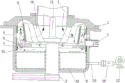
At present, most of flour mill systems consist of a mill, a classifier, a cyclone separator, a pulse dust removal box and an induced draft fan system. The pulverizer mainly has two forms of mechanical crushing and airflow crushing, the airflow mill mainly crushes micro powder, the yield is low, the energy consumption is high, the mechanical crushing is used for producing products with thicker particle sizes, and the yield is high and the energy consumption is relatively low. The pulverizer has a simple structure and high pulverizing efficiency, and is widely applied. The working principle is that materials to be crushed are thrown out of an impact gear ring along the tangential direction through impact columns on a grinding disc rotating at a high speed, crushed in a crushing area of a pulverizer, and then enter a separation area from top to bottom along the outer wall of a backflow ring via an inner wall under the action of wind force of an induced draft fan to be sprayed out of a discharge port after passing through a fan blade classifier. Because the centrifugal force that the high-speed rotation of fan blade classificator produced makes the material pass through the hindrance in this separation process, and when the granule was great, the resistance was great, and the material can not be through the classificator forced to revolve and smash once more on the mill, and only after the granule reached certain particle diameter, the material could pass the fan blade classificator when draught fan wind-force was greater than to its suction and divides the machine to its resistance, breaks away from the constraint and discharges the milling machine via the discharge gate. The existing flour mill can be divided into three areas, (1) a crushing area A, namely an area formed by a hitting column, the inner wall of a gear ring and the outer side of a backflow ring, and has the main function of crushing material particles; (2) the screening area B, namely an area formed by the impeller classifier and the inner side of the backflow ring, is mainly used for screening certain particle materials; (3) the return area C, namely the area formed by the bottom of the classifier, the bottom of the backflow ring and the middle part of the grinding disc, mainly plays a role of throwing coarse particle powder which does not pass through the impeller of the classifier out again to enter the crushing area. The existing flour mill has the problems that (1) coarse materials which are not ground are required to leave a grinding area A under the drive of high-speed airflow, enter a screening area B and then return to the grinding area A from the screening area B, the continuous circulation is carried out until the required particle size is reached, the gas flow mode inside the flour mill is shown in figure 1, the coarse powder which is ground does not stay in the grinding area A within a certain time, a large amount of crushing opportunities are lost, and the milling efficiency of the flour mill is not high; (2) because the material and the air flow do not ideally flow in a single direction, the short path can be selected due to the air flow, the optimal path of the air flow is usually from the gap between the bottom of the backflow ring and the grinding disc and directly upwards enters the classifier, the coarse powder is influenced to enter the grinding area A again, a large amount of material is stagnated in the central area of the grinding disc, and the coarse powder cannot be effectively crushed; (3) a part of the ground powder enters the grinding area A and then is crushed again, so that the content of the superfine powder is increased, the particle size distribution of the product is more dispersed, and the crushing efficiency is reduced; (4) because the powder stays in the cavity of the flour mill for a long time, the temperature in the flour mill rises, the softening point of the material is further reduced, and the crushing efficiency is further influenced; (5) because a large amount of coarse particle materials enter the screening area B, the probability that the coarse particle materials enter finished powder through the classifier is increased, and the screening efficiency is reduced.
Disclosure of Invention
To the above problem, the utility model provides a boiling formula milling machine through the mill that increases boiling wind dish and area direction function to the milling machine bottom for treat that the crushing material forms the ebullated bed, different according to material weight, in the milling machine internal part layering, the middlings granule obtains the crushing of maximum, the milling machine can be discharged in time to the screening of farine granule, crocus efficiency obtains the improvement of maximum, and powder particle size distribution is more concentrated simultaneously, improves milling machine finished product yield and quality. Therefore, the utility model provides a following technical scheme:
a boiling type pulverizer comprises a grinding cover, a feeding port, a grinding body shell, a transmission device, a gear ring, a grinding disc, a backflow ring, a classifier, a transmission shaft, a fan and a boiling air disc, wherein the bottom end of the grinding body shell is connected with the transmission shaft inside through the transmission device; the outer edge of the boiling air disc is tightly attached to the inner wall of the grinding body shell, and a ventilation cavity is arranged in the boiling air disc and is communicated with a fan outside the pulverizer through an air delivery pipe; the grinding disc comprises an outer ring plate, fan blades and a shaft hoop, wherein the outer ring plate is fixedly connected with the shaft hoop which is positioned in the outer ring plate and concentrically arranged through the fan blades.
In the above, the height H of the fan blade is greater than the thickness H of the outer annular plate, and the height of the upper edge of the fan blade is greater than the height of the gap between the backflow ring and the grinding disc.
in the above, the radial connection between the fan blade and the shaft hoop and the radial connection between the fan blade and the outer ring plate form an included angle α, where α is less than or equal to 30 ° and less than or equal to 60 °, and the length L of the fan blade is greater than the distance R between the outer circumference of the shaft hoop and the inner circumference of the outer ring plate.
The boiling air disc comprises a boiling disc body, a shaft sleeve for the transmission shaft to penetrate is arranged in the center of the boiling disc body, and the upper plate surface of the boiling disc body is a porous plate.
The grinding body shell positioned above the replaceable impact column of the grinding disc is provided with more than two air inlet holes.
The replaceable impact column is fixed on the outer ring plate through the retaining nut.
And an air cooler is fixedly connected between the air delivery pipe and the fan.
The feeding port is fixedly arranged on one side of the outer wall of the grinding body shell corresponding to the replaceable striking column grinding disc.
In the above, a discharge port is arranged above the center of the grinding disc corresponding to the classifier.
The utility model relates to a rationally, novel, gain following technological effect:
1. the boiling air disc is additionally arranged at the bottom of the pulverizer, and particulate materials in the pulverizer form layers, so that fine particle materials can be discharged in time conveniently, the residence time of large particle materials in the pulverizing area A is prolonged, and the working efficiency of the pulverizer is improved;
2. the air inlet positions are reasonably arranged, so that coarse particle materials in the crushing area A are prevented from being brought into the grading area B by strong air flow, the probability of the coarse particle materials entering the classifier is reduced, and the particle size distribution of finished powder is more concentrated;
3. the grinding disc with the guiding function is additionally arranged, the fan blades of the grinding disc are reasonably arranged, the air sweeping area in the rotating process of the grinding disc is increased, meanwhile, coarse particle materials in the returning area C are thrown into the crushing area A in time, the detention of the materials in the returning area C is reduced, the detention time of the materials in the crushing area A is prolonged, and the crushing efficiency of the coarse particle materials is improved;
4. the milling efficiency of the system is obviously improved, the particle size distribution is more concentrated, and the yield and the quality of finished products of the flour mill are effectively improved.
Drawings
In order to more clearly illustrate the embodiments of the present application or the technical solutions in the prior art, the drawings needed to be used in the embodiments will be briefly described below, and it is obvious that the drawings in the following description are only some embodiments described in the present invention, and other drawings can be obtained by those skilled in the art according to these drawings.
FIG. 1 is a schematic view of the flow of raw gas inside the main body according to the embodiment of the present invention;
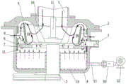
FIG. 2 is a schematic view of the gas flow structure inside the main body according to the embodiment of the present invention;
FIG. 3 is a schematic diagram of a grinding disc structure according to an embodiment of the present invention;
FIG. 4 is a top view of a grinding disc and impact post mounting structure according to an embodiment of the present invention;
FIG. 5 is a bottom view of the millstone and impact post mounting structure of the embodiment of the invention;
fig. 6 is a schematic structural view of a boiling wind disk according to an embodiment of the present invention.
Reference numerals:
1-discharge port, 2-grinding cover, 3-feeding port, 4-grinding body shell, 5-transmission device, 6-air inlet hole, 7-gear ring, 8-grinding disc, 801-outer ring plate, 802-fan blade, 803-shaft hoop, 804-column hitting mounting hole, 805-replaceable column hitting, 806-backstop nut, 9-backflow ring, 10-classifier, 11-transmission shaft, 12-fan, 13-air transmission pipe 1401, 14-boiling air disc, 1402-boiling disc body, 1402-shaft sleeve, 1403-air hole, 15-annular mounting table, 16-air cooler, A-crushing area, B-screening area, C-return area and D-ventilation cavity.
Detailed description of the preferred embodiments
In order to make those skilled in the art better understand the solution of the embodiments of the present invention, the embodiments of the present invention are further described in detail below with reference to the accompanying drawings and the implementation manner.
It should be noted that: like reference numbers and letters refer to like items in the following figures, and thus, once an item is defined in one figure, it need not be further defined and explained in subsequent figures.
In the description of the present application, it should be noted that the terms "upper", "lower", "left", "right", "vertical", "horizontal", "inside", "outside", and the like indicate orientations or positional relationships based on the orientations or positional relationships shown in the drawings or orientations or positional relationships that the products of the present invention are conventionally placed in use, and are used only for convenience of describing the present application and for simplicity of description, and do not indicate or imply that the devices or elements being referred to must have a specific orientation, be constructed and operated in a specific orientation, and thus, should not be construed as limiting the present application.
In the description of the present application, it is also to be noted that, unless otherwise explicitly specified or limited, the terms "disposed," "mounted," "connected," and "connected" are to be construed broadly and may, for example, be fixedly connected, detachably connected, or integrally connected. The specific meaning of the above terms in the present application can be understood in a specific case by those of ordinary skill in the art.
Embodiment 1, refer to fig. 1 to 3, a boiling type pulverizer comprises a mill cover 2, a feeding port 3, a mill body shell 4, a transmission device 5, a gear ring 7, a mill disc 8, a backflow ring 9, a classifier 10, a transmission shaft 11, a fan 12 and a boiling air disc 14, wherein the bottom end of the mill body shell 4 is connected with the transmission shaft 11 inside through the transmission device 5, the boiling air disc 14 is fixedly sleeved on the outer edge of the transmission shaft 11, the mill disc 8 and the classifier 10 are fixedly sleeved on the transmission shaft 11, the backflow ring 9 is fixedly arranged between the mill disc 8 and the classifier 10 on a mill body, and the gear ring 7 is fixedly arranged on an annular mounting table 15 on the inner wall of the mill body shell 4; the outer edge of the boiling air disc 14 is tightly attached to the inner wall of the grinding body shell 4, a ventilation cavity D is arranged in the boiling air disc, the ventilation cavity D is communicated with a fan 12 on the outer side of the grinding machine through an air conveying pipe 13, and an air cooler 16 is fixedly connected between the air conveying pipe 13 and the fan 12, so that air entering the grinding machine is cooled when the temperature of air in a workshop is high; the grinding disc 8 comprises an outer ring plate 801, fan blades 802 and a shaft hoop 803, wherein the outer ring plate 801 is fixedly connected with the shaft hoop 803 concentrically arranged in the outer ring plate 801 through the fan blades 802. When the pulverizer works, air is injected into a ventilation cavity D in the boiling air disc 14 through the fan 12, air flow is uniformly sprayed into the cavity of the pulverizer from the upper plate surface of the boiling air disc 14, so that materials to be pulverized are uniformly layered in the cavity of the pulverizer, large-particle-diameter particles are deposited at the lower part of the pulverizer, small-particle materials are lighter in weight and migrate upwards to rise, the air quantity is adjusted through the fan 12, coarse powder basically stays in a pulverizing area A, fine-particle materials enter a screening area B through a draught fan (not shown in the figure and positioned above a discharge port 1) and are screened and separated through the classifier 10, a small amount of coarse-particle materials fall along the backflow ring 9 under the action of centrifugal force of the classifier 10 and are thrown to the pulverizing area A through the fan blades 802 on the grinding disc at the bottom of the backflow ring 9 to be pulverized, and guide fan blades are arranged in the center of the grinding disc 8, the production throws the air current to the circumference outside, throws the large granule material once more and gets into crushing zone A, has reduced the large granule material and has returned regional C detention time on mill 8 for the material gets into milling zone A fast, and the effect through removable hitting post 805 on the mill 8 and ring gear 7 is broken once more, and its gas flow state is as shown in fig. 2.
referring to fig. 3-5, a plurality of impact column mounting holes 804 are formed in the outer ring plate 801, replaceable impact columns 805 are fixed on the outer ring plate 801 through retaining nuts 806, the height H of a fan blade 802 is larger than the thickness H of the outer ring plate 801, the height of the upper edge of the fan blade 802 is larger than the height of a gap between a backflow ring 9 and a grinding disc 8, the fan blade 802 is radially connected with a shaft hoop 803 and the outer ring plate 801 to form an included angle of α, the included angle of α is 30 degrees less than or equal to 60 degrees, the length L of the fan blade is larger than the distance R between the outer circumference of the shaft hoop 803 and the inner circumference of the outer ring plate 801, the structure is beneficial to increasing the wind sweeping area of the fan blade 802, and meanwhile, coarse particulate materials are conveniently and efficiently thrown into a.
Referring to fig. 6, the boiling wind plate 14 includes a boiling plate 1401, a shaft sleeve 1402 for the transmission shaft 11 to pass through is disposed at the center of the boiling plate 1401, the upper plate surface of the boiling plate 1401 is a porous plate, the outer circumference of the boiling plate 1401 is closely attached to the inner wall of the grinding body housing 4, and when the device works, the compressed wind is uniformly ejected from the ventilation cavity D through the plate surface of the boiling plate 1401, so as to provide suspension power for the material to be pulverized.
Referring to fig. 1-2, the feeding port 3 is fixedly arranged on one side of the outer wall of the grinding body shell 4 corresponding to the replaceable column hitting grinding disc 8, so that a stable fluidized bed can be formed after materials to be ground enter the grinding mill; the grinding body shell 4 above the replaceable impact column 805 on the grinding disc 8 is provided with a circle of a plurality of air inlet holes 6, the air inlet holes 6 are positioned at the upper end of the grinding area A, the air volume entering the ventilation cavity D through the fan 12 only provides power for forming a fluidized bed for materials to be ground, the air volume is not large, the air inlet holes 6 positioned above the grinding area A uniformly enter the upper layer of the grinding area A through the air inlet holes 6 under the action of the induced draft fan above the discharge port 1, the ground fine-grained materials are positioned on the upper layer of the fluidized bed, the air volume entering through the air inlet holes 6 is carried into the screening area B for screening operation, the large-grained materials enter the returning area C through the backflow ring 9, the arrangement effectively prevents the materials in the grinding area A from being brought into the grading area B by strong airflow, thereby increasing the retention time of coarse powder at the grinding area A and reducing the probability of the coarse-grained materials entering the classifier 10, the grinding efficiency of the flour mill is improved, repeated grinding of fine particle materials is avoided, and the particle size distribution of finished material products is more concentrated; a discharge port 1 is arranged above the center of the grinding disc 2 corresponding to the classifier 10, and the upper part of the discharge port 1 is connected with a finished product collecting system and a dust collecting system through a draught fan.
While the preferred embodiments of the present invention have been described in the foregoing illustrative manner, it will be understood by those skilled in the art that the described embodiments may be modified in various different ways without departing from the spirit and scope of the present invention.
Claims (9)
1. A boiling mill, characterized by: the device comprises a grinding cover (2), a feeding port (3), a grinding body shell (4), a transmission device (5), a gear ring (7), a grinding disc (8), a backflow ring (9), a classifier (10), a transmission shaft (11), a fan (12) and a boiling air disc (14), wherein the bottom end of the grinding body shell (4) is connected with the transmission shaft (11) inside through the transmission device (5), the boiling air disc (14) is fixedly sleeved on the outer edge of the transmission shaft (11), the grinding disc (8) and the classifier (10) are fixedly sleeved on the transmission shaft (11), the backflow ring (9) is fixedly arranged between the grinding disc (8) and the classifier (10) and on a grinding body, and the gear ring (7) is fixedly arranged on an annular mounting table (15) on the inner wall of the grinding body shell (4); the outer edge of the boiling air disc (14) is tightly attached to the inner wall of the grinding body shell (4), and a ventilation cavity (D) is arranged in the boiling air disc, and the ventilation cavity (D) is communicated with a fan (12) outside the pulverizer through an air conveying pipe (13); the grinding disc (8) comprises an outer ring plate (801), fan blades (802) and a shaft hoop (803), wherein the outer ring plate (801) is fixedly connected with the shaft hoop (803) which is concentrically arranged in the outer ring plate (801) through the fan blades (802).
2. A boiling mill according to claim 1, characterized in that: the height H of the fan blade (802) is larger than the thickness H of the outer ring plate (801), and the height of the upper edge of the fan blade (802) is larger than the height of a gap between the backflow ring (9) and the grinding disc (8).
3. A boiling mill according to claim 1, characterized in that said blades (802) are radially connected to the collar (803) and the outer ring plate (801) at an angle α, which is between 30 ° and 60 °, and the length L of the blades is larger than the distance R between the outer circumference of the collar (803) and the inner circumference of the outer ring plate (801).
4. A boiling mill according to claim 1, characterized in that: the boiling wind plate (14) comprises a boiling plate body (1401), a shaft sleeve (1402) for the transmission shaft (11) to penetrate through is arranged in the center of the boiling plate body (1401), and the upper plate surface of the boiling plate body (1401) is a porous plate.
5. A boiling mill according to claim 1, characterized in that: the grinding body shell (4) positioned above the replaceable impact column (805) of the grinding disc (8) is provided with more than two air inlet holes (6).
6. A boiling mill according to claim 1, characterized in that: the surface of the outer ring plate (801) is provided with a plurality of striking post mounting holes (804), and the replaceable striking post (805) is fixed on the outer ring plate (801) through the retaining nut (806).
7. A boiling mill according to claim 1, characterized in that: an air cooler (16) is fixedly connected between the air delivery pipe (13) and the fan (12).
8. A boiling mill according to claim 1, characterized in that: the feeding port (3) is fixedly arranged on one side of the outer wall of the grinding body shell (4) corresponding to the replaceable striking column grinding disc (8).
9. A boiling mill according to claim 1, characterized in that: a discharge hole (1) is arranged above the center of the grinding disc (8) corresponding to the classifier (10).
Priority Applications (1)
| Application Number | Priority Date | Filing Date | Title |
|---|---|---|---|
| CN201921179260.4U CN210545566U (en) | 2019-07-25 | 2019-07-25 | Boiling type pulverizer |
Applications Claiming Priority (1)
| Application Number | Priority Date | Filing Date | Title |
|---|---|---|---|
| CN201921179260.4U CN210545566U (en) | 2019-07-25 | 2019-07-25 | Boiling type pulverizer |
Publications (1)
| Publication Number | Publication Date |
|---|---|
| CN210545566U true CN210545566U (en) | 2020-05-19 |
Family
ID=70670554
Family Applications (1)
| Application Number | Title | Priority Date | Filing Date |
|---|---|---|---|
| CN201921179260.4U Active CN210545566U (en) | 2019-07-25 | 2019-07-25 | Boiling type pulverizer |
Country Status (1)
| Country | Link |
|---|---|
| CN (1) | CN210545566U (en) |
Cited By (1)
| Publication number | Priority date | Publication date | Assignee | Title |
|---|---|---|---|---|
| WO2022252388A1 (en) * | 2021-05-31 | 2022-12-08 | 华中科技大学 | Horizontal interlayer fluidized-bed biomass micron fuel crusher and method of using same |
-
2019
- 2019-07-25 CN CN201921179260.4U patent/CN210545566U/en active Active
Cited By (1)
| Publication number | Priority date | Publication date | Assignee | Title |
|---|---|---|---|---|
| WO2022252388A1 (en) * | 2021-05-31 | 2022-12-08 | 华中科技大学 | Horizontal interlayer fluidized-bed biomass micron fuel crusher and method of using same |
Similar Documents
| Publication | Publication Date | Title |
|---|---|---|
| CN101767049B (en) | Vertical multi-stage coaxial impact crushing sorting unit | |
| CN209020487U (en) | Bidentate ring micronizer | |
| CN106824452A (en) | Fluidized bed airflow grinding machine intelligence change system | |
| CN210965355U (en) | Mineral powder vertical mill with multistage sorting mechanism | |
| CN114273023B (en) | Superfine pulverizer and material pulverizing method | |
| CN210753092U (en) | Millstone type pulverizer with guide fan blades | |
| CN210545566U (en) | Boiling type pulverizer | |
| CN209302870U (en) | A kind of spreading is evenly distributed with the roller type vertical mill of spout ring | |
| CN2439326Y (en) | Vertical, high speed impact type disintegrating system | |
| CN201609671U (en) | Vertical multistage coaxial impact crushing separator | |
| CN204159418U (en) | Reducing mechanism | |
| CN104014413B (en) | A kind of enclosed comminuting matter gathering-device and collection method | |
| CN212164268U (en) | Shearing and impact composite crushing biomass ultrafine crushing device | |
| CN108906272A (en) | A kind of three cutterhead mechanical shock high speed of servo-drive is to grinding machine | |
| CN202162054U (en) | High-effect whirlpool mill | |
| CN209423734U (en) | A kind of multiple groups tup micronizer | |
| CN2601740Y (en) | Superfine internal -grading centrifugal circular grinder | |
| CN215878794U (en) | Novel powder selecting device | |
| CN109772519A (en) | It crushes wind and send all-in-one machine | |
| CN102836766A (en) | Circulating type jet mill and milling system thereof | |
| CN207013103U (en) | Fluidized bed airflow grinding machine intelligence change system | |
| CN1599646A (en) | Grinding or polishing method of pneumatic grading and separating and special equipment | |
| CN111686880B (en) | Double-stage ultrafine grinder | |
| CN209613119U (en) | It crushes wind and send all-in-one machine | |
| CN209613127U (en) | A kind of roller type vertical mill |
Legal Events
| Date | Code | Title | Description |
|---|---|---|---|
| GR01 | Patent grant | ||
| GR01 | Patent grant |