CN210540511U - Rotary cup cover and beverage cup with same - Google Patents
Rotary cup cover and beverage cup with same Download PDFInfo
- Publication number
- CN210540511U CN210540511U CN201921077414.9U CN201921077414U CN210540511U CN 210540511 U CN210540511 U CN 210540511U CN 201921077414 U CN201921077414 U CN 201921077414U CN 210540511 U CN210540511 U CN 210540511U
- Authority
- CN
- China
- Prior art keywords
- hole
- locking
- cup
- rotating shaft
- cup cover
- Prior art date
- Legal status (The legal status is an assumption and is not a legal conclusion. Google has not performed a legal analysis and makes no representation as to the accuracy of the status listed.)
- Active
Links
- 235000013361 beverage Nutrition 0.000 title claims abstract description 25
- XLYOFNOQVPJJNP-UHFFFAOYSA-N water Substances O XLYOFNOQVPJJNP-UHFFFAOYSA-N 0.000 claims abstract description 99
- 238000007789 sealing Methods 0.000 claims abstract description 62
- 210000000078 claw Anatomy 0.000 claims description 10
- 230000000149 penetrating effect Effects 0.000 claims description 3
- 230000000903 blocking effect Effects 0.000 abstract description 5
- 230000000694 effects Effects 0.000 abstract description 2
- 238000003756 stirring Methods 0.000 abstract description 2
- 230000035622 drinking Effects 0.000 description 5
- 238000000034 method Methods 0.000 description 2
- 238000000926 separation method Methods 0.000 description 2
- VYPSYNLAJGMNEJ-UHFFFAOYSA-N Silicium dioxide Chemical group O=[Si]=O VYPSYNLAJGMNEJ-UHFFFAOYSA-N 0.000 description 1
- 241001122767 Theaceae Species 0.000 description 1
- 230000001580 bacterial effect Effects 0.000 description 1
- 238000004891 communication Methods 0.000 description 1
- 238000011109 contamination Methods 0.000 description 1
- 238000010586 diagram Methods 0.000 description 1
- 239000003651 drinking water Substances 0.000 description 1
- 235000020188 drinking water Nutrition 0.000 description 1
- 239000012535 impurity Substances 0.000 description 1
- 238000001802 infusion Methods 0.000 description 1
- 239000008267 milk Substances 0.000 description 1
- 210000004080 milk Anatomy 0.000 description 1
- 235000013336 milk Nutrition 0.000 description 1
- 239000002245 particle Substances 0.000 description 1
- 239000000843 powder Substances 0.000 description 1
- 238000005406 washing Methods 0.000 description 1
Images


Classifications
-
- B—PERFORMING OPERATIONS; TRANSPORTING
- B65—CONVEYING; PACKING; STORING; HANDLING THIN OR FILAMENTARY MATERIAL
- B65D—CONTAINERS FOR STORAGE OR TRANSPORT OF ARTICLES OR MATERIALS, e.g. BAGS, BARRELS, BOTTLES, BOXES, CANS, CARTONS, CRATES, DRUMS, JARS, TANKS, HOPPERS, FORWARDING CONTAINERS; ACCESSORIES, CLOSURES, OR FITTINGS THEREFOR; PACKAGING ELEMENTS; PACKAGES
- B65D47/00—Closures with filling and discharging, or with discharging, devices
- B65D47/04—Closures with discharging devices other than pumps
- B65D47/20—Closures with discharging devices other than pumps comprising hand-operated members for controlling discharge
- B65D47/26—Closures with discharging devices other than pumps comprising hand-operated members for controlling discharge with slide valves, i.e. valves that open and close a passageway by sliding over a port, e.g. formed with slidable spouts
- B65D47/261—Closures with discharging devices other than pumps comprising hand-operated members for controlling discharge with slide valves, i.e. valves that open and close a passageway by sliding over a port, e.g. formed with slidable spouts having a rotational or helicoidal movement
- B65D47/266—Closures with discharging devices other than pumps comprising hand-operated members for controlling discharge with slide valves, i.e. valves that open and close a passageway by sliding over a port, e.g. formed with slidable spouts having a rotational or helicoidal movement the rotational movement being transmitted by displacement of an additional external element, e.g. overcap
-
- A—HUMAN NECESSITIES
- A47—FURNITURE; DOMESTIC ARTICLES OR APPLIANCES; COFFEE MILLS; SPICE MILLS; SUCTION CLEANERS IN GENERAL
- A47G—HOUSEHOLD OR TABLE EQUIPMENT
- A47G19/00—Table service
- A47G19/22—Drinking vessels or saucers used for table service
- A47G19/2205—Drinking glasses or vessels
- A47G19/2266—Means for facilitating drinking, e.g. for infants or invalids
- A47G19/2272—Means for facilitating drinking, e.g. for infants or invalids from drinking glasses or cups comprising lids or covers
-
- B—PERFORMING OPERATIONS; TRANSPORTING
- B65—CONVEYING; PACKING; STORING; HANDLING THIN OR FILAMENTARY MATERIAL
- B65D—CONTAINERS FOR STORAGE OR TRANSPORT OF ARTICLES OR MATERIALS, e.g. BAGS, BARRELS, BOTTLES, BOXES, CANS, CARTONS, CRATES, DRUMS, JARS, TANKS, HOPPERS, FORWARDING CONTAINERS; ACCESSORIES, CLOSURES, OR FITTINGS THEREFOR; PACKAGING ELEMENTS; PACKAGES
- B65D43/00—Lids or covers for rigid or semi-rigid containers
- B65D43/02—Removable lids or covers
- B65D43/0202—Removable lids or covers without integral tamper element
- B65D43/0225—Removable lids or covers without integral tamper element secured by rotation
- B65D43/0229—Removable lids or covers without integral tamper element secured by rotation only on the inside, or a part turned to the inside, of the mouth of the container
-
- B—PERFORMING OPERATIONS; TRANSPORTING
- B65—CONVEYING; PACKING; STORING; HANDLING THIN OR FILAMENTARY MATERIAL
- B65D—CONTAINERS FOR STORAGE OR TRANSPORT OF ARTICLES OR MATERIALS, e.g. BAGS, BARRELS, BOTTLES, BOXES, CANS, CARTONS, CRATES, DRUMS, JARS, TANKS, HOPPERS, FORWARDING CONTAINERS; ACCESSORIES, CLOSURES, OR FITTINGS THEREFOR; PACKAGING ELEMENTS; PACKAGES
- B65D47/00—Closures with filling and discharging, or with discharging, devices
- B65D47/04—Closures with discharging devices other than pumps
- B65D47/20—Closures with discharging devices other than pumps comprising hand-operated members for controlling discharge
- B65D47/26—Closures with discharging devices other than pumps comprising hand-operated members for controlling discharge with slide valves, i.e. valves that open and close a passageway by sliding over a port, e.g. formed with slidable spouts
- B65D47/261—Closures with discharging devices other than pumps comprising hand-operated members for controlling discharge with slide valves, i.e. valves that open and close a passageway by sliding over a port, e.g. formed with slidable spouts having a rotational or helicoidal movement
- B65D47/265—Closures with discharging devices other than pumps comprising hand-operated members for controlling discharge with slide valves, i.e. valves that open and close a passageway by sliding over a port, e.g. formed with slidable spouts having a rotational or helicoidal movement between planar parts
-
- B—PERFORMING OPERATIONS; TRANSPORTING
- B65—CONVEYING; PACKING; STORING; HANDLING THIN OR FILAMENTARY MATERIAL
- B65D—CONTAINERS FOR STORAGE OR TRANSPORT OF ARTICLES OR MATERIALS, e.g. BAGS, BARRELS, BOTTLES, BOXES, CANS, CARTONS, CRATES, DRUMS, JARS, TANKS, HOPPERS, FORWARDING CONTAINERS; ACCESSORIES, CLOSURES, OR FITTINGS THEREFOR; PACKAGING ELEMENTS; PACKAGES
- B65D51/00—Closures not otherwise provided for
- B65D51/16—Closures not otherwise provided for with means for venting air or gas
- B65D51/1672—Closures not otherwise provided for with means for venting air or gas whereby venting occurs by manual actuation of the closure or other element
-
- B—PERFORMING OPERATIONS; TRANSPORTING
- B65—CONVEYING; PACKING; STORING; HANDLING THIN OR FILAMENTARY MATERIAL
- B65D—CONTAINERS FOR STORAGE OR TRANSPORT OF ARTICLES OR MATERIALS, e.g. BAGS, BARRELS, BOTTLES, BOXES, CANS, CARTONS, CRATES, DRUMS, JARS, TANKS, HOPPERS, FORWARDING CONTAINERS; ACCESSORIES, CLOSURES, OR FITTINGS THEREFOR; PACKAGING ELEMENTS; PACKAGES
- B65D2543/00—Lids or covers essentially for box-like containers
- B65D2543/00009—Details of lids or covers for rigid or semi-rigid containers
- B65D2543/00018—Overall construction of the lid
- B65D2543/00046—Drinking-through lids
-
- B—PERFORMING OPERATIONS; TRANSPORTING
- B65—CONVEYING; PACKING; STORING; HANDLING THIN OR FILAMENTARY MATERIAL
- B65D—CONTAINERS FOR STORAGE OR TRANSPORT OF ARTICLES OR MATERIALS, e.g. BAGS, BARRELS, BOTTLES, BOXES, CANS, CARTONS, CRATES, DRUMS, JARS, TANKS, HOPPERS, FORWARDING CONTAINERS; ACCESSORIES, CLOSURES, OR FITTINGS THEREFOR; PACKAGING ELEMENTS; PACKAGES
- B65D2543/00—Lids or covers essentially for box-like containers
- B65D2543/00009—Details of lids or covers for rigid or semi-rigid containers
- B65D2543/00018—Overall construction of the lid
- B65D2543/00064—Shape of the outer periphery
- B65D2543/00074—Shape of the outer periphery curved
- B65D2543/00092—Shape of the outer periphery curved circular
-
- B—PERFORMING OPERATIONS; TRANSPORTING
- B65—CONVEYING; PACKING; STORING; HANDLING THIN OR FILAMENTARY MATERIAL
- B65D—CONTAINERS FOR STORAGE OR TRANSPORT OF ARTICLES OR MATERIALS, e.g. BAGS, BARRELS, BOTTLES, BOXES, CANS, CARTONS, CRATES, DRUMS, JARS, TANKS, HOPPERS, FORWARDING CONTAINERS; ACCESSORIES, CLOSURES, OR FITTINGS THEREFOR; PACKAGING ELEMENTS; PACKAGES
- B65D2543/00—Lids or covers essentially for box-like containers
- B65D2543/00009—Details of lids or covers for rigid or semi-rigid containers
- B65D2543/00444—Contact between the container and the lid
- B65D2543/00481—Contact between the container and the lid on the inside or the outside of the container
- B65D2543/0049—Contact between the container and the lid on the inside or the outside of the container on the inside, or a part turned to the inside of the mouth of the container
- B65D2543/00509—Cup
Landscapes
- Engineering & Computer Science (AREA)
- Mechanical Engineering (AREA)
- Health & Medical Sciences (AREA)
- General Health & Medical Sciences (AREA)
- Pediatric Medicine (AREA)
- Closures For Containers (AREA)
Abstract
The utility model relates to a rotary cup cover and a beverage cup with the rotary cup cover, the rotary cup cover comprises a cup cover body, the cup cover body is provided with a rotating shaft hole, a water outlet hole and an air inlet hole, and the rotary cup cover is characterized by also comprising a knob part, a water blocking device and a movable part; set up apopore and inlet port on the bowl cover body, set up apopore sealing and inlet port sealing on the ware of hindering, through stirring the knob part, the pivot on by the knob part is movably fixed the movable part on hindering the ware, make to drive pivoted locking portion via the pivot and move on the locking track (from the orbital high-end of locking to the low side removal), reach the roof pressure to hindering the ware, make and hinder the ware and respectively correspond the apopore of sealing up the bowl cover body and seal up the inlet port of bowl cover body correspondingly, realize the effect that the user closes the apopore of rotation type bowl cover, thereby make things convenient for the beverage to drink. When the water is not required to be drunk, the knob part is pulled in the opposite direction.
Description
Technical Field
The utility model relates to a goblet field especially relates to a rotation type bowl cover and have goblet of this rotation type bowl cover.
Background
As part of the taste of modern life, more and more consumers prefer to choose different drinking cups for the infusion of various beverages, such as coffee or milk tea.
Beverage cups currently used by consumers generally include a lid and a cup body that is screw-fitted to the lid. When a consumer uses the beverage cups, the tightly screwed cup cover is separated from the cup body to expose the cup mouth of the cup body, and then beverage particles (or beverage powder) and water are put into the cup body to be stirred, so that the required beverage is obtained; after drinking, the cup cover is screwed to the cup body, and the cup opening is sealed.
However, these prior art drinking cups suffer from several disadvantages: as the important structure of beverage cup, the mode that the rim of a cup is directly sealed to present bowl cover adoption bowl cover body more, if the user drinks beverage, need to separate bowl cover and cup completely, will lead to the rim of a cup of cup to be exposed in the air completely, the beverage in the cup is direct to contact with outside air, and not only inconvenient user drinks beverage like this, and the beverage in the cup also receives impurity or bacterial contamination in the air easily moreover.
SUMMERY OF THE UTILITY MODEL
The utility model aims to solve the technical problem of providing a rotary cup cover aiming at the prior art. This rotation type bowl cover can seal the apopore on the bowl cover more reliably to also convenience of customers disassembles the washing.
The utility model aims to solve another technical problem of providing a beverage cup with the rotary cup cover aiming at the prior art.
The utility model provides a technical scheme that above-mentioned technical problem adopted is: rotation type bowl cover, including the bowl cover body, the bowl cover body has pivot hole, apopore and inlet port, its characterized in that, the rotation type bowl cover still includes:
the knob component is provided with a rotating shaft penetrating through the rotating shaft hole and can be rotatably assembled on the cup cover body through the matching of the rotating shaft and the rotating shaft hole;
the water blocking device is provided with an opening through which the front end of the rotating shaft passes, one end of the water blocking device is provided with a water outlet hole sealing part capable of sealing a water outlet hole, the other end of the water blocking device is provided with an air inlet hole sealing part capable of sealing an air inlet hole, and a locking track is formed on the bottom surface of the water blocking device and around the opening;
the movable part is provided with a rotating shaft clamping hole for firmly clamping the rotating shaft and a locking part which can move on the locking track along the forming direction of the locking track;
the front end of the rotating shaft sequentially penetrates through the rotating shaft hole, the opening and the rotating shaft clamping hole and then is fastened on the movable part; the water outlet hole sealing part and the air inlet hole sealing part of the water stopper can correspondingly seal the water outlet hole and the air inlet hole on the cup cover body along with the movement of the locking part on the locking track.
The improved rotary cup cover is characterized in that the locking rail is a slope-shaped locking rail with one high end and one low end, the high end and the low end of the slope-shaped locking rail are provided with locking grooves matched with the locking portions to enter, and the movable portion is matched with the locking grooves correspondingly to realize that the movable portion can rotate along the forming direction of the locking rail.
Furthermore, the movable part is provided with two symmetrical locking parts, and the locking rail of the water stopper is provided with two slope-shaped locking rails which are centrosymmetric.
And in the rotary cup cover, the bottom of the movable part is provided with a clamping claw, and the front end of the rotating shaft sequentially passes through the rotating shaft hole, the open hole and the rotating shaft clamping hole and then is firmly clamped by the clamping claw of the movable part.
Further, the chucking claw is formed of a movable portion.
In the rotary cup cover, a toggle part for a user to rotate the knob component is arranged on the knob component.
Furthermore, the top surface of the cup cover body is provided with a circular wall which is formed along the edge direction of the cup cover body and extends upwards, the rotating shaft hole, the water outlet hole and the air inlet hole are all positioned on the inner side of the circular wall, the shifting part is provided with a clamping groove which is buckled on the circular wall in a matched mode, and the shifting part can move along the circular wall in a sliding mode through the matching of the clamping groove and the circular wall.
Optionally, in the rotary cup cover, the front end of the rotating shaft is provided with a prism, and a clamping part is formed on the prism; or a supporting part for supporting the water stopper is formed on the inner side of the bottom of the cup cover body and around the rotating shaft hole; or at least two limiting columns capable of limiting the swing of the water outlet hole sealing part are formed on the inner side of the bottom of the cup cover body.
In the rotary cup cover, a sealing ring for sealing a gap between the rotary shaft and the rotary shaft hole is arranged on the rotary shaft.
The utility model provides a technical scheme that another technical problem of above-mentioned adopts does: the beverage cup with the rotary cup cover comprises a cup body and is characterized in that the rotary cup cover is screwed on the cup body.
Compared with the prior art, the utility model has the advantages of:
first, the utility model provides a rotation type bowl cover is through setting up apopore and inlet port on the bowl cover body, set up apopore sealing and inlet port sealing on the ware of hindering water, through stirring the knob part, with movably fixing the movable part on the ware of hindering water by the pivot on the knob part, make and drive pivoted locking portion via the pivot and move on the locking track (remove towards the low side from the orbital high-end of locking), reach the roof pressure to hindering the water ware, thereby make the ware of hindering water seal the apopore of bowl cover body and seal the inlet port of bowl cover body respectively correspondingly, realize the effect that the user closed the apopore of rotation type bowl cover, thereby conveniently drink beverage. When drinking water is needed, the knob component is shifted in the opposite direction, so that the locking part of the movable part finally moves from the low end to the high end of the locking track, the water outlet hole sealing part of the water stopper does not seal the water outlet hole of the cup cover body any more, the air inlet hole of the cup cover body is not sealed any more, the communication between the air in the cup body and the outside air is realized, and the water in the cup body can conveniently flow out from the water outlet hole of the cup cover body;
secondly, the rotary cup cover structure of the utility model adopts a connection mode of easy disassembly, which is convenient for users to disassemble the rotary cup cover and clean each component in time;
thirdly, the slope-shaped locking rails for the locking parts of the movable parts to move are symmetrically arranged on the water stopper, so that the locking parts can move along the direction of the slope-shaped locking rails to press the water stopper, and finally the water outlet hole sealing parts and the air inlet hole sealing parts on the water stopper can correspondingly seal the water outlet holes and the air inlet holes on the cup cover body more gently and more powerfully;
finally, the low end and the high end of the slope-shaped locking track of the water stopper are provided with locking grooves for the locking parts of the matched movable parts to enter, so that when the locking parts enter the corresponding locking grooves or move out of the corresponding locking grooves, certain 'clicking' sound can be emitted between the locking parts and the locking grooves due to the forced friction, and a user can conveniently judge whether the water inlet hole of the cup cover body is closed or opened currently through the 'clicking' sound.
Drawings
FIG. 1 is a schematic structural view of a rotary cup lid in an embodiment of the present invention;
FIG. 2 is a back structure view of the rotatable cup lid shown in FIG. 1;
FIG. 3 is a schematic view of the lid of FIG. 1 from another perspective;
FIG. 4 is a cross-sectional view of the swivel cup lid shown in FIG. 1;
FIG. 5 is an exploded view of the lid of FIG. 1;
FIG. 6 is a schematic structural view of a knob member in the present embodiment;
FIG. 7 is a schematic view of a back structure of the cup lid body in this embodiment;
FIG. 8 is a schematic structural diagram of a water stopper in the present embodiment;
FIG. 9 is a schematic view of the water trap shown in FIG. 8 from another perspective;
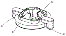
FIG. 10 is a schematic structural view of the movable portion in the present embodiment;
fig. 11 is a schematic structural view of the beverage cup of the present embodiment.
Detailed Description
The present invention will be described in further detail with reference to the following embodiments.
As shown in fig. 1 to 5, the rotary cup lid in this embodiment includes a cup lid body 1, the cup lid body 1 has a rotary shaft hole 11, a water outlet hole 12 and an air inlet hole 13, and the rotary shaft hole 11, the water outlet hole 12 and the air inlet hole 13 are preferably arranged on the same straight line; as the improvement, the rotary cup cover also comprises:
the knob component 2 is provided with a rotating shaft 21 penetrating through the rotating shaft hole 11, and the knob component 2 is rotatably assembled on the cup cover body 1 through the matching of the rotating shaft 21 and the rotating shaft hole 11; for example, the knob component 2 may have a toggle portion 22 for the user to rotate the knob component, so that the user can conveniently realize the rotation of the knob component by toggling the toggle portion 22;
specifically, in this embodiment, the top surface of the lid body 1 further has an annular wall 14 formed along the edge direction of the lid body and extending upward, the rotation shaft hole 11, the water outlet hole 12 and the air inlet hole 13 are all located on the inner side of the annular wall 14, the toggle part 22 has a locking groove 220 locked on the annular wall 14 in a matching manner, and the toggle part 22 can slidably move along the annular wall 14 through the locking groove 220 and the annular wall 14 in a matching manner. As regards the structure of the knob part 2 and the toggle part 22, reference is made to fig. 5 and 6;
a water stopper 3, the water stopper 3 having an opening 31 through which the front end of the rotating shaft 21 passes, one end of the water stopper 3 having a water outlet hole sealing portion 32 capable of sealing the water outlet hole 12, the other end of the water stopper 3 having an air inlet hole sealing portion 33 capable of sealing the air inlet hole 13, a locking rail 34 formed on the bottom surface of the water stopper 3 and around the opening 31; referring to fig. 5, the outlet hole sealing portion 32 of the embodiment includes an outlet sealing protrusion 321 formed by a water stopper and an outlet sealing ring 322 disposed on the outlet sealing protrusion 321; also, the intake hole sealing portion 33 in this embodiment includes an intake port sealing protrusion 331 formed of a water stopper and an intake port sealing ring 332 provided on the intake port sealing protrusion 331; the water outlet sealing ring 322 and the air inlet sealing ring 332 can be silica gel rings according to requirements; in order to avoid the separation of the outlet sealing ring 322 from the outlet sealing protrusion 321 and the separation of the inlet sealing ring 332 from the inlet sealing protrusion 331, referring to fig. 5, it is also possible to connect a fastening cap 35 to each of the outlet sealing ring 322 and the inlet sealing ring 332, and the water stopper 3 has two fixing devices 36 for tightly covering the corresponding fastening caps 35. Namely, the fastening connection cap 35 connected with the water outlet sealing ring 322 is tightly sleeved on one fixing 36 on the water stopper 3, and the fastening connection cap 35 connected with the air inlet sealing ring 332 is tightly sleeved on the other fixing 36 on the water stopper 3;
a movable portion 4 having a shaft engaging hole 41 for engaging with the shaft 21 and a locking portion 42 movable on the locking rail 34 in a direction in which the locking rail is formed;
wherein, the front end of the rotating shaft 21 passes through the rotating shaft hole 11, the opening hole 31 and the rotating shaft clamping hole 41 in sequence and then is fastened on the movable part 4; the water outlet hole sealing part 32 and the air inlet hole sealing part 33 of the water stopper 3 can correspondingly seal the water outlet hole 12 and the air inlet hole 13 on the cup cover body 1 along with the movement of the locking part 42 on the locking rail 34.
In the present embodiment, referring to fig. 3, 4, 5 and 8, the locking rail 34 in the present embodiment has at least one slope-shaped locking rail with one high end and the other low end, the high end and the low end of the slope-shaped locking rail each have a locking groove 340 for engaging with the corresponding locking portion 42, and the movable portion 4 is enabled to rotate along the forming direction of the locking rail 34 by the corresponding engagement between the locking portion 42 and the locking grooves 340. The movable part 4 here preferably has two symmetrical locking parts 42, and the locking track 34 of the water trap 3 has two centrally symmetrical ramp-shaped locking tracks. The locking portion 42 preferably has a spherical end, and the cross section of the locking groove 340 is arc-shaped, so that the end of the locking portion 42 can move out or in the locking groove 340 smoothly. The following is a description of the movement of the lock portion 42 on the lock rail 34:
by dialing the toggle component 22 on the knob component 2 along one direction, when the movable part 4 rotates due to the rotating shaft 21, and one locking part 42 (assuming that the locking part 42 corresponds to the water outlet sealing part 32) on one end of the movable part 4 moves from the high end to the low end thereof along the corresponding slope-shaped locking track, the locking part 42 applies a jacking force towards the water outlet sealing part 32, so that the water outlet sealing part 32 jacks and seals the water outlet 12, thereby preventing subsequent water from flowing out from the water outlet 12 of the cup cover body, and achieving the purpose of closing the water outlet on the cup cover; similarly, the locking portion 42 on the other end of the movable portion 4 (the locking portion 42 corresponds to the intake hole sealing portion 33) can also make the intake hole sealing portion 33 press and seal the intake hole 13. Of course, if the toggle component 22 on the knob component 2 is toggled along another direction, the water outlet sealing portion 32 can no longer press the sealed water outlet 12, the air inlet sealing portion 33 can no longer press the air inlet 13, so far, the water outlet on the cup cover is opened, and the subsequent water flow can flow out from the water outlet 12.
As a structural arrangement manner for fastening the front end of the rotating shaft to the movable portion after passing through the rotating shaft hole, the opening hole, and the rotating shaft fastening hole in sequence, referring to fig. 3, 4, and 10, in the present embodiment, the bottom of the movable portion 4 has a fastening claw 43, and the front end of the rotating shaft 21 passes through the rotating shaft hole 11, the opening hole 31, and the rotating shaft fastening hole 41 in sequence and is fastened by the fastening claw 43 of the movable portion. The clamping claw 43 here is preferably formed by the movable part 4. In addition, the number of the chucking claws 43 may be set as needed.
Referring to fig. 6, the front end of the rotating shaft 21 has a prism 211, and a fastening part 212 is formed on the prism 211, and the fastening part 212 is fixed to the movable part 4. The shaft 21 may further have a seal 213 for sealing a gap between the shaft 21 and the shaft hole 11, thereby preventing water from flowing out of the gap. Specifically, the prism 211 may be a quadrangular prism having a rectangular cross section; correspondingly, the rotating shaft clamping hole 41 on the movable part 4 is also an opening with a rectangular cross section and matched with the quadrangular prism, and then the side edges of the prism 211 are fastened with the rotating shaft clamping hole 41 of the movable part 4.
Of course, a support portion 15 for supporting the water stopper 3 may be formed on the inner side of the bottom of the cup lid body 1 and around the rotating shaft hole 11, so that the distance between the water stopper 3 and the cup lid body 1 is ensured by the support portion 15. It should be noted that, referring to fig. 2 and 7, at least two limiting columns 16 capable of limiting the swing of the water outlet sealing portion 32 are formed on the inner side of the bottom of the cup lid body 1.
In the embodiment, a double-layer thread matched with the cup body is formed on the inner wall of the cup cover body 1, so that the drinking requirement when a user holds the beverage cup with a left hand or a right hand can be matched.
The following description will be made with reference to fig. 1 to 10, after the rotary cup lid of the embodiment is screwed to a cup body containing beverage, with respect to the use process of the rotary cup lid:
firstly, a user pulls the pulling part 22 of the knob part 2 to make the rotating shaft 21 on the knob part 2 drive the movable part 4 to rotate; the two locking portions 42 of the movable portion 4 move along the corresponding sloping locking tracks;
when the locking part 42 moves out of the locking groove 340 corresponding to the high end of the slope-shaped locking track and moves into the locking groove 340 at the low end of the slope-shaped locking track, the two locking parts on the movable part 4 can press the water stopper 3;
the jacked water stopper 3 moves towards the direction of the cup cover body 1, so that the water outlet hole sealing part 32 of the water stopper 3 seals the water outlet hole 12 of the cup cover body 1, the air inlet hole sealing part 33 of the water stopper 3 seals the air inlet hole 13 of the cup cover body, and at the moment, the whole rotary cup cover is in a closed state, and no beverage flows out from the water outlet hole 12;
secondly, the user pulls the pulling part 22 of the knob part 2 in the opposite direction, so that the rotating shaft 21 of the knob part 2 drives the movable part 4 to rotate again; the two locking portions 42 of the movable portion 4 move correspondingly in the opposite direction (i.e. from the lower end of the ramp locking track towards the upper end):
when the locking part 141 moves out of the locking groove 340 at the lower end of the slope-shaped locking track and moves into the locking groove 340 at the high end of the slope-shaped locking track, the two locking parts 42 on the movable part 4 reduce the jacking pressure on the water stopper 3;
the water stopper 3 displaces towards the direction deviating from the cup cover body 1, so that the water outlet hole sealing part 32 of the water stopper 3 leaves the water outlet hole 12 and the air inlet hole sealing part 33 of the water stopper 3 leaves the air inlet hole 13, the rotary cup cover is in an open state at the moment, the air pressure in the cup body is communicated with the air pressure outside the cup body through the air inlet hole 13 of the cup cover, and the beverage can flow out from the water outlet hole 12 of the rotary cup cover.
Referring to fig. 11, the present embodiment also provides a drinking cup having a cup body 6 and a rotatable lid in the present embodiment that is screwed to the cup body 6. The specific using process of the beverage cup is referred to the foregoing content, and the detailed description is omitted here.
Claims (10)
1. Rotation type bowl cover, including bowl cover body (1), the bowl cover body has pivot hole (11), apopore (12) and inlet port (13), its characterized in that, the rotation type bowl cover still includes:
the rotary knob component (2) is provided with a rotary shaft (21) penetrating through the rotary shaft hole (11), and the rotary knob component (2) is rotatably assembled on the cup cover body (1) through the matching of the rotary shaft (21) and the rotary shaft hole (11);
the water stopping device (3) is provided with an opening (31) through which the front end (210) of the rotating shaft (21) passes, one end of the water stopping device (3) is provided with a water outlet hole sealing part (32) capable of sealing a water outlet hole (12), the other end of the water stopping device (3) is provided with an air inlet hole sealing part (33) capable of sealing an air inlet hole (13), and a locking track (34) is formed on the bottom surface of the water stopping device (3) and around the opening (31);
a movable part (4), wherein the movable part (4) is provided with a rotating shaft clamping hole (41) for clamping the rotating shaft (21) and a locking part (42) capable of moving on the locking track (34) along the forming direction of the locking track;
the front end (210) of the rotating shaft (21) sequentially penetrates through the rotating shaft hole (11), the opening hole (31) and the rotating shaft clamping hole (41) and then is fastened on the movable part (4); the water outlet hole sealing part (32) and the air inlet hole sealing part (33) of the water stopper (3) can correspondingly seal the water outlet hole (12) and the air inlet hole (13) on the cup cover body along with the movement of the locking part (42) on the locking rail (34).
2. The rotatable cup cover according to claim 1, characterized in that the locking track (34) has at least one slope-shaped locking track with one high end and the other low end, the high end and the low end of the slope-shaped locking track are respectively provided with a locking groove (340) which is matched with the corresponding locking portion (42) to enter, and the movable portion (4) can rotate along the forming direction of the locking track through the corresponding matching between the locking portion (42) and the locking groove (340).
3. The rotatable cup lid according to claim 2, characterised in that the movable part (4) has two symmetrical locking parts (42), and the locking track (34) of the water stopper (3) has two centrally symmetrical ramp-shaped locking tracks.
4. The rotatable cup cover according to claim 1, characterized in that the bottom of the movable part (4) is provided with a clamping claw (43), and the front end (210) of the rotating shaft (21) passes through the rotating shaft hole (11), the opening (31) and the rotating shaft clamping hole (41) in sequence and then is clamped by the clamping claw (43) of the movable part.
5. A rotatable cup lid according to claim 4, characterized in that the gripping claw (43) is formed by the movable portion (4).
6. A rotatable cup lid according to claim 1, characterised in that the knob member (2) is provided with a dial portion (22) for rotation of the knob member by a user.
7. The rotatable cup cover according to claim 6, characterized in that the top surface of the cup cover body (1) is provided with an annular wall (14) which is formed along the edge direction of the cup cover body and extends upwards, the rotating shaft hole (11), the water outlet hole (12) and the air inlet hole (13) are all located on the inner side of the annular wall (14), the toggle part (22) is provided with a clamping groove (220) which is clamped on the annular wall (14) in a matching mode, and the toggle part (22) can move along the annular wall (14) in a sliding mode through the matching of the clamping groove (220) and the annular wall (14).
8. The rotatable cup cover according to claim 1, characterized in that the front end (210) of the rotary shaft (21) has a prism body (211), and a clamping part (212) is formed on the prism body (211); or a supporting part (15) for supporting the water stopper (3) is formed on the inner side of the bottom of the cup cover body (1) and around the rotating shaft hole (11); or at least two limiting columns (16) capable of limiting the swing of the water outlet hole sealing part (32) are formed on the inner side of the bottom of the cup cover body (1).
9. A rotatable cup lid according to claim 1, characterised in that the rotary shaft (21) is provided with a seal ring (213) for sealing a gap between the rotary shaft (21) and the rotary shaft hole (11).
10. Beverage cup with a rotatable lid as claimed in any one of claims 1 to 9, comprising a cup body (6), wherein the rotatable lid is screwed onto the cup body.
Priority Applications (3)
| Application Number | Priority Date | Filing Date | Title |
|---|---|---|---|
| CN201921077414.9U CN210540511U (en) | 2019-07-10 | 2019-07-10 | Rotary cup cover and beverage cup with same |
| US16/632,479 US20210403207A1 (en) | 2019-07-10 | 2019-07-26 | A Rotary Lid and a Drinking Cup Thereof |
| PCT/CN2019/097887 WO2021003778A1 (en) | 2019-07-10 | 2019-07-26 | Rotary lid and beverage cup with same |
Applications Claiming Priority (1)
| Application Number | Priority Date | Filing Date | Title |
|---|---|---|---|
| CN201921077414.9U CN210540511U (en) | 2019-07-10 | 2019-07-10 | Rotary cup cover and beverage cup with same |
Publications (1)
| Publication Number | Publication Date |
|---|---|
| CN210540511U true CN210540511U (en) | 2020-05-19 |
Family
ID=70663281
Family Applications (1)
| Application Number | Title | Priority Date | Filing Date |
|---|---|---|---|
| CN201921077414.9U Active CN210540511U (en) | 2019-07-10 | 2019-07-10 | Rotary cup cover and beverage cup with same |
Country Status (3)
| Country | Link |
|---|---|
| US (1) | US20210403207A1 (en) |
| CN (1) | CN210540511U (en) |
| WO (1) | WO2021003778A1 (en) |
Cited By (1)
| Publication number | Priority date | Publication date | Assignee | Title |
|---|---|---|---|---|
| US12082725B2 (en) | 2021-05-07 | 2024-09-10 | Milwaukee Electric Tool Corporation | Beverage container cover assembly |
Families Citing this family (4)
| Publication number | Priority date | Publication date | Assignee | Title |
|---|---|---|---|---|
| CN112107205A (en) * | 2019-06-21 | 2020-12-22 | 宁波利时日用品有限公司 | Coaxial rotary cup cover and drinking cup with same |
| CN113180364B (en) * | 2021-04-30 | 2022-11-08 | 上海雨豪日用制品有限公司 | Linkage sealing cup cover and cup |
| US12030025B2 (en) * | 2021-10-21 | 2024-07-09 | Blendjet Inc. | Drinking lid |
| USD1037769S1 (en) * | 2022-04-08 | 2024-08-06 | Ozean International Inc | Lid for beverage container |
Family Cites Families (6)
| Publication number | Priority date | Publication date | Assignee | Title |
|---|---|---|---|---|
| US8573431B2 (en) * | 2011-09-07 | 2013-11-05 | Pacific Market International, Llc | Beverage container closure with venting |
| CN206284747U (en) * | 2016-08-12 | 2017-06-30 | 保丽金国际贸易有限公司 | Rotation cup lid |
| CN207428875U (en) * | 2017-03-17 | 2018-06-01 | 杭州吻吻鱼科技有限公司 | A kind of rotary cup cover |
| CN207886066U (en) * | 2017-09-15 | 2018-09-21 | 武义鑫禾日用品有限公司 | A kind of rotary cup cover |
| CN208740566U (en) * | 2018-05-03 | 2019-04-16 | 珠海德豪润达电气有限公司 | Vacuum cup lid, vacuum cup and vacuum stirring cup |
| CN108669963B (en) * | 2018-05-07 | 2024-04-19 | 宁波利时日用品有限公司 | Novel rotary cup cover and beverage cup with same |
-
2019
- 2019-07-10 CN CN201921077414.9U patent/CN210540511U/en active Active
- 2019-07-26 US US16/632,479 patent/US20210403207A1/en not_active Abandoned
- 2019-07-26 WO PCT/CN2019/097887 patent/WO2021003778A1/en active Application Filing
Cited By (1)
| Publication number | Priority date | Publication date | Assignee | Title |
|---|---|---|---|---|
| US12082725B2 (en) | 2021-05-07 | 2024-09-10 | Milwaukee Electric Tool Corporation | Beverage container cover assembly |
Also Published As
| Publication number | Publication date |
|---|---|
| US20210403207A1 (en) | 2021-12-30 |
| WO2021003778A1 (en) | 2021-01-14 |
Similar Documents
| Publication | Publication Date | Title |
|---|---|---|
| CN210540511U (en) | Rotary cup cover and beverage cup with same | |
| CN108669963B (en) | Novel rotary cup cover and beverage cup with same | |
| CN112107205A (en) | Coaxial rotary cup cover and drinking cup with same | |
| CN105852570B (en) | A kind of cup lid and cup of one-handed performance cup | |
| CN205658732U (en) | Bowl cover and cup of one -hand operation cup | |
| CN218044652U (en) | Turnover-piece type locking cup cover and coffee cup | |
| WO2020192559A1 (en) | Lid with liftable and lowerable straw and cup thereof | |
| CN216932655U (en) | Single-cover double-drinking cup cover and cup | |
| CN216569442U (en) | Double-cup cover and cup | |
| CN211242697U (en) | Double-drinking-water-opening cup | |
| CN217065979U (en) | Rotary cup cover | |
| CN112617558A (en) | Spherical omnibearing sliding cover | |
| CN219289172U (en) | Cup cover with upper cover opening and closing structure and cup | |
| CN217338132U (en) | Novel cup capable of making tea | |
| CN215993552U (en) | Vacuum cup with openable cup mouth | |
| CN213664691U (en) | Water-blocking air inlet structure of double drinking cup | |
| CN214433486U (en) | Spherical omnibearing sliding cover | |
| CN215382993U (en) | Toggle switch cover | |
| CN216454461U (en) | Cup cover and drinking cup | |
| CN220466268U (en) | Press-opening type drinking bottle | |
| CN218899105U (en) | Push-button type cup capable of preventing from being opened by mistake | |
| CN216293695U (en) | Multifunctional magnetic suction double-drinking cup cover and cup | |
| CN212912171U (en) | Anti-overflow bowl cover | |
| CN219500789U (en) | Cup cover and cup | |
| CN220069392U (en) | Rotary double-drink spring-jumping cup cover |
Legal Events
| Date | Code | Title | Description |
|---|---|---|---|
| GR01 | Patent grant | ||
| GR01 | Patent grant |