Disclosure of Invention
The utility model discloses a solve traditional culvert axle measurement technique measurement inefficiency, measure the poor problem of accuracy, provide a portable culvert axle measuring tool.
The utility model discloses an adopt following technical scheme to realize:
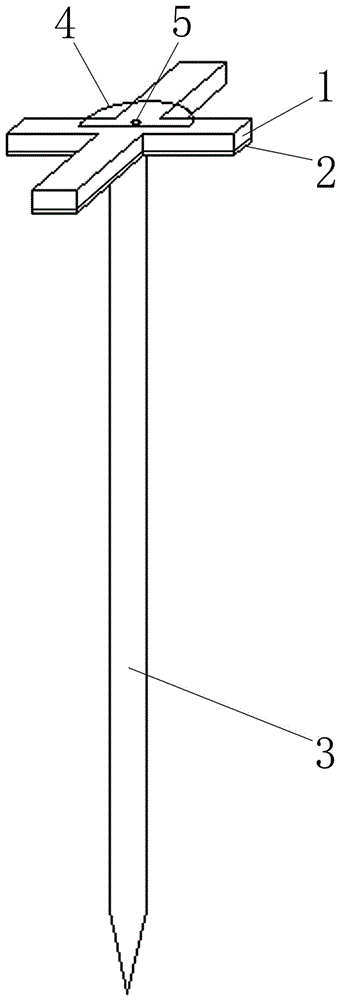
a portable culvert shaft measuring tool comprises a cross-shaped wood frame, a cross-shaped iron sheet, a positioning rod and a protractor; the upper surface of the cross-shaped iron sheet is contacted with the lower surface of the cross-shaped wooden frame, and the end surface of the cross-shaped iron sheet is flush with the end surface of the cross-shaped wooden frame; the surface of each beam arm of the cross-shaped iron sheet is provided with a plurality of vertically through round holes; the upper end surface of the positioning rod is welded and fixed with the center of the lower surface of the cross-shaped iron sheet; the lower end of the positioning rod is pointed; the lower surface of the protractor is contacted with the upper surface of the cross-shaped wood frame, and the circle center of the protractor is superposed with the center of the cross-shaped wood frame; the surface of the protractor is provided with a circular hole which is communicated up and down, and the circle center of the circular hole is superposed with the center of the cross-shaped wooden frame; a steel nail is arranged in each round hole of the protractor and each round hole of the cross iron sheet in a penetrating mode, and the nail tip of each steel nail is nailed into the inside of the cross wood frame.
The specific using process is as follows: firstly, the positioning rod is vertically inserted into the ground, and the inserted position of the positioning rod is the number of the central pile of the culvert, so that the cross-shaped wooden frame and the cross-shaped iron sheet are both parallel to the ground. Then, the positioning rod is rotated, so that the two longitudinal beam arms of the cross-shaped wooden frame and the cross-shaped iron sheet are respectively aligned with the pile in the forward direction of the route and the pile in the backward direction of the route, and therefore the two transverse beam arms of the cross-shaped wooden frame and the cross-shaped iron sheet are both perpendicular to the direction of the route. Then, the protractor is rotated around the steel nail, so that the straight edge of the protractor is used as a culvert axis, the included angle between a zero scale line of the protractor and a longitudinal beam arm of the cross-shaped wooden frame is read at the moment, the included angle is the included angle between the culvert axis and a route, and then the ground elevation is measured through a GPS or a total station by aiming at and commanding a measurer on a topographic change point through eyes along two directions pointed by the straight edge of the protractor with the positioning rod as a starting point, so that the measurement of the culvert axis is realized.
Based on above-mentioned process, compare with traditional culvert axle measurement technique, a portable culvert axle measuring tool through adopting brand-new structure, realized the measurement of culvert axle, its measurement of efficiency is higher with the measurement accuracy, has effectively improved the efficiency and the precision of culvert design and construction from this.
The utility model discloses rational in infrastructure, design benefit have effectively solved traditional culvert axle and have measured the problem that technical measurement is inefficient, the measurement accuracy is poor, are applicable to the culvert design and construction.
Detailed Description
A portable culvert shaft measuring tool comprises a cross-shaped wood frame 1, a cross-shaped iron sheet 2, a positioning rod 3 and a protractor 4; the upper surface of the cross-shaped iron sheet 2 is contacted with the lower surface of the cross-shaped wooden frame 1, and the end surface of the cross-shaped iron sheet 2 is flush with the end surface of the cross-shaped wooden frame 1; the surface of each beam arm of the cross-shaped iron sheet 2 is provided with a plurality of vertically through round holes; the upper end surface of the positioning rod 3 is welded and fixed with the center of the lower surface of the cross-shaped iron sheet 2; the lower end of the positioning rod 3 is pointed; the lower surface of the protractor 4 is contacted with the upper surface of the cross-shaped wood frame 1, and the circle center of the protractor 4 is superposed with the center of the cross-shaped wood frame 1; the surface of the protractor 4 is provided with a circular hole which is communicated up and down, and the circle center of the circular hole is superposed with the center of the cross-shaped wooden frame 1; a steel nail 5 is arranged in each round hole of the angle gauge 4 and each round hole of the cross iron sheet 2 in a penetrating mode, and the nail tip of each steel nail 5 is nailed into the cross wooden frame 1.