CN210242599U - Practical coal mine underground tunnel measuring device - Google Patents
Practical coal mine underground tunnel measuring device Download PDFInfo
- Publication number
- CN210242599U CN210242599U CN201921183426.XU CN201921183426U CN210242599U CN 210242599 U CN210242599 U CN 210242599U CN 201921183426 U CN201921183426 U CN 201921183426U CN 210242599 U CN210242599 U CN 210242599U
- Authority
- CN
- China
- Prior art keywords
- measuring device
- face
- ruler body
- coal mine
- chi body
- Prior art date
- Legal status (The legal status is an assumption and is not a legal conclusion. Google has not performed a legal analysis and makes no representation as to the accuracy of the status listed.)
- Expired - Fee Related
Links
Images


Abstract
The utility model discloses a practical moulded coal mine underworkings measuring device, its structure includes the first chi body, the air level, first scale, a groove, auxiliary measuring device and fixed orifices, through having set up auxiliary measuring device in first chi body bottom face, exert the pulling force to the handle after that, the handle passes through the axis of rotation with the fixed plate and rotates on the second chi body, make fixed block and fixed orifices separation, then exert the pulling force to the first chi body, the recess in the first chi body passes through the spout and slides on the slide rail on the second chi body, replenish the length measurement, reached and to slide the extension to the level bar, increase measuring range, and is convenient to carry, use convenient beneficial effect.
Description
Technical Field
The utility model relates to a colliery underworkings equipment technical field, concretely relates to practical moulded coal mine underworkings measuring device.
Background
The mine tunnel is excavated in different directions and different dip angles in different rock according to different sections and lengths, serves different ranges and is used as a general name of various underground spaces with different purposes, the mine tunnel is named and classified according to the space size, dip angle direction, position, service range, purposes and the like, underground measurement refers to all measurement work in mines during mine construction and production, and is mainly responsible for data entry engineering, development engineering, through engineering and the like of tunnel construction.
SUMMERY OF THE UTILITY MODEL
Technical problem to be solved
In order to overcome the prior art not enough, provide a practical coal mine underworkings measuring device at present to solve the measuring distance and very limit to, can not extend and carry out the auxiliary measurement, the poor problem of activity has reached and can slide the extension to the spirit level, increases measuring range, portable uses convenient effect.
(II) technical scheme
The utility model discloses a following technical scheme realizes: the utility model provides a practical coal mine underground roadway measuring device, which comprises a first ruler body, a level bubble, a first graduated scale, a groove, an auxiliary measuring device and a fixed hole, wherein the level bubble is arranged in the middle of the top end of the first ruler body, the lower end of the front end surface of the first ruler body is bonded with the first graduated scale through super glue, the groove is arranged in the middle of the inner part of the first ruler body, the auxiliary measuring device is arranged on the bottom end surface of the first ruler body, two fixed holes are arranged and are distributed on the left end surface and the right end surface of the first ruler body side by side, the auxiliary measuring device is composed of a second ruler body, a slide rail, a slide groove, a support plate, a second graduated scale and a fixed mechanism, the middle of the top end of the second ruler body is welded with the bottom end surface of the slide rail through a hand mode, the slide rail is provided with the slide groove at the front end and the rear end surfaces, the right end surface of, the lower end of the front end face of the second ruler body is bonded with the second graduated scale through a super glue, a fixing mechanism is arranged in the middle of the left end face of the second ruler body, and the sliding rail is in sliding connection with the inner side of the groove through the outer side of the sliding groove.
Further, fixed establishment includes fixed plate, handle, axis of rotation and fixed block, fixed plate left end face upper end carries out fixed connection with the handle right-hand member face, the middle part is provided with the axis of rotation in the fixed plate bottom, fixed plate right-hand member face carries out fixed connection with the fixed block, both ends rotate with second chi body left end face middle part about the axis of rotation and are connected.
Further, the outer diameter of the sliding rail is smaller than the inner diameter of the groove by 3 MM.
Further, the second graduated scale and the first graduated scale are the same in size, and the surface of the second graduated scale is smooth.
Further, the combined height of the second ruler body and the first ruler body is equal to the height of the supporting plate.
Furthermore, the inner side of the handle is provided with anti-skid grains, and the height of the anti-skid grains is 2 MM.
Further, the outer diameter dimension of the fixing block is smaller than the inner diameter dimension 2MM of the fixing hole, and a rubber layer is disposed outside the fixing block 564.
Furthermore, the first ruler body is made of PVC plastic.
Furthermore, the slide rail is made of stainless steel.
(III) advantageous effects
Compared with the prior art, the utility model, following beneficial effect has: for solving prior art measurement distance ten limitations, can not extend and carry out the auxiliary measurement, the poor problem of activity, through having set up auxiliary measurement device in first chi body bottom face, apply the pulling force to the handle after that, the handle passes through the axis of rotation with the fixed plate and rotates on the second chi body, make fixed block and fixed orifices separation, then apply the pulling force to the first chi body, recess in the first chi body slides on the slide rail of second chi body through the spout, replenish the length measurement, reached and to have slided the extension to the level bar, increase measuring range, and is convenient to carry, use convenient beneficial effect.
Drawings
Other features, objects and advantages of the invention will become more apparent upon reading of the detailed description of non-limiting embodiments with reference to the following drawings:
fig. 1 is a schematic structural view of the present invention;
FIG. 2 is a schematic structural view of the fixing mechanism of the present invention;
FIG. 3 is a schematic structural view of the auxiliary measuring device of the present invention;
fig. 4 is a schematic structural view of the fixing mechanism of the present invention;
fig. 5 is a schematic structural view of the inner side of the fixing mechanism of the present invention;
in the figure: the measuring instrument comprises a first ruler body-1, a level bubble-2, a first graduated scale-3, a groove-4, an auxiliary measuring device-5, a fixing hole-6, a second ruler body-51, a sliding rail-52, a sliding groove-53, a supporting plate-54, a second graduated scale-55, a fixing mechanism-56, a fixing plate-561, a handle-562, a rotating shaft-563 and a fixing block-564.
Detailed Description
In order to make the objects, technical solutions and advantages of the present invention more clearly understood, the present invention is further described in detail below with reference to the accompanying drawings and embodiments. It should be understood that the specific embodiments described herein are merely illustrative of the invention and are not intended to limit the invention.
Referring to fig. 1, fig. 2, fig. 3, fig. 4 and fig. 5, the present invention provides a practical coal mine underworkings measuring device: the measuring device comprises a first ruler body 1, a leveling bubble 2, a first graduated scale 3, a groove 4, an auxiliary measuring device 5 and a fixed hole 6, wherein the leveling bubble 2 is arranged in the middle of the top end of the first ruler body 1, the lower end of the front end face of the first ruler body 1 is bonded with the first graduated scale 3 through super glue, the groove 4 is arranged in the middle of the inner part of the first ruler body 1, the auxiliary measuring device 5 is arranged on the bottom end face of the first ruler body 1, the fixed holes 6 are arranged in two and are distributed on the left end face and the right end face of the left end face of the first ruler body 1 side by side, the auxiliary measuring device 5 comprises a second ruler body 51, a slide rail 52, a slide groove 53, a support plate 54, a second graduated scale 55 and a fixing mechanism 56, the middle of the top end of the second ruler body 51 is welded with the bottom end face of the slide rail 52 through a hand welding mode, the slide grooves 53 are arranged at the, the lower end of the front end face of the second ruler body 51 is bonded with the second graduated scale 55 through super glue, the middle part of the left end face of the second ruler body 51 is provided with a fixing mechanism 56, and the sliding rail 52 is in sliding connection with the inner side of the groove 4 through the outer side of the sliding groove 53.
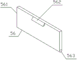
The fixing mechanism 56 comprises a fixing plate 561, a handle 562, a rotating shaft 563 and a fixing block 564, the upper end of the left end face of the fixing plate 561 is fixedly connected with the right end face of the handle 562, a rotating shaft 563 is arranged in the middle of the bottom end of the fixing plate 561, the right end face of the fixing plate 561 is fixedly connected with the fixing block 564, and the left end and the right end of the rotating shaft 563 are rotatably connected with the middle of the left end face of the second ruler body 51.
The outer diameter of the slide rail 52 is smaller than the inner diameter of the groove 4 by 3MM, so that the slide rail 52 can slide normally in the groove 4.
The second graduated scale 55 and the first graduated scale 3 are the same in size, smooth in surface and moderate in size, and measurement is convenient.
The combined height of the second ruler body 51 and the first ruler body 1 is equal to the height of the supporting plate 54, the height is moderate, and the fixity is strong.
Wherein, the handle 562 is provided with anti-slip lines on the inner side, and the height of the anti-slip line is 2MM, so as to avoid the hand slip during operation.
The outer diameter of the fixing block 564 is smaller than the inner diameter of the fixing hole 6 by 2MM, and a rubber layer is arranged outside the fixing block 564 for facilitating clamping and fixing.
The first ruler body 1 is made of PVC plastic, and is firm and durable, high in cost performance, corrosion-resistant and light in weight.
Wherein, the slide rail 52 is made of stainless steel.

According to the table shown above; the utility model discloses slide rail 52 adopts the stainless steel, can reach non-deformable, and is with low costs, the effect of sexual valence relative altitude.
The patent states: the precision of the vial 2, also known as the angle value, refers to the angle of inclination of the vial when the bubble moves 2mm in any radial direction from the center of the line of differentiation for a round vial, and to the angle of inclination of the vial when the bubble moves 2mm in the axial direction of the vial for a long vial.
The working principle is as follows: firstly, a practical coal mine underground roadway measuring device is placed at a proper position, then the distance required to be measured under the mine is measured through a second graduated scale 55 on a second ruler body 51, the leveling bubble 2 can be used for horizontal testing, when the measuring length is too long and the measuring device is not enough to measure, an auxiliary measuring device 5 is arranged on the bottom end face of the first ruler body 1, then pulling force is applied to a handle 562, anti-slip patterns are arranged on the inner side of the handle 562, the protruding height of the anti-slip patterns is 2MM, the phenomenon that the hands slip is caused during operation is avoided, the handle 562 rotates a fixing plate 561 on the second ruler body 51 through a rotating shaft 563 to separate the fixing block 564 from a fixing hole 6, then the pulling force is applied to the first ruler body 1, a groove 4 in the first ruler body 1 slides on a sliding rail 52 on the second ruler body 51 through a sliding groove 53, the second graduated scale 55 is supplemented through the first graduated scale 3, the length measurement is supplemented, the sliding extension of the level ruler is achieved, the measuring range is increased, the carrying is convenient, the use is convenient and fast, the beneficial effects are achieved, and the problems that the measuring distance is very limited, the extension cannot be performed, the auxiliary measurement cannot be performed, and the mobility is poor in the prior art are solved.
The basic principles and the main features of the invention and the advantages of the invention have been shown and described above, it will be evident to those skilled in the art that the invention is not limited to the details of the foregoing illustrative embodiments, but that the invention may be embodied in other specific forms without departing from the spirit or essential characteristics of the invention. The present embodiments are therefore to be considered in all respects as illustrative and not restrictive, the scope of the invention being indicated by the appended claims rather than by the foregoing description, and all changes which come within the meaning and range of equivalency of the claims are therefore intended to be embraced therein. Any reference sign in a claim should not be construed as limiting the claim concerned.
Furthermore, it should be understood that although the present description refers to embodiments, not every embodiment may contain only a single embodiment, and such description is for clarity only, and those skilled in the art should integrate the description, and the embodiments may be combined as appropriate to form other embodiments understood by those skilled in the art.
Claims (7)
1. A practical coal mine underground roadway measuring device comprises a first ruler body (1), a leveling bubble (2), a first graduated scale (3), a groove (4) and fixing holes (6), wherein the leveling bubble (2) is arranged in the middle of the top end of the first ruler body (1), the lower end of the front end face of the first ruler body (1) is bonded with the first graduated scale (3) through strong glue, the groove (4) is arranged in the middle of the inside of the first ruler body (1), an auxiliary measuring device (5) is arranged on the bottom end face of the first ruler body (1), and the two fixing holes (6) are distributed at the left end and the right end of the left end face of the first ruler body (1) side by side;
the method is characterized in that: still include auxiliary measuring device (5), auxiliary measuring device (5) comprises second chi body (51), slide rail (52), spout (53), backup pad (54), second scale (55) and fixed establishment (56), second chi body (51) top middle part is welded through the mode of hand arc welding with slide rail (52) bottom face, both ends are provided with spout (53) around slide rail (52), second chi body (51) and slide rail (52) right-hand member face carry out fixed connection with backup pad (54) left end face, second chi body (51) front end face lower extreme bonds with second scale (55) through powerful glue, second chi body (51) left end face middle part is provided with fixed establishment (56), slide rail (52) carry out sliding connection through spout (53) outside and recess (4) inboard.
2. The practical coal mine underground roadway measuring device according to claim 1, is characterized in that: fixed establishment (56) include fixed plate (561), handle (562), axis of rotation (563) and fixed block (564), fixed plate (561) left end face upper end carries out fixed connection with handle (562) right-hand member face, the middle part is provided with axis of rotation (563) in fixed plate (561) bottom, fixed plate (561) right-hand member face carries out fixed connection with fixed block (564), both ends rotate with second chi body (51) left end face middle part about axis of rotation (563) and are connected.
3. The practical coal mine underground roadway measuring device according to claim 1, is characterized in that: the outer diameter of the sliding rail (52) is smaller than the inner diameter of the groove (4) by 3 MM.
4. The practical coal mine underground roadway measuring device according to claim 1, is characterized in that: the second graduated scale (55) and the first graduated scale (3) are the same in size, and the surface of the second graduated scale is smooth.
5. The practical coal mine underground roadway measuring device according to claim 1, is characterized in that: the combined height of the second ruler body (51) and the first ruler body (1) is equal to the height of the supporting plate (54).
6. The practical coal mine underground roadway measuring device according to claim 2, is characterized in that: the inner side of the handle (562) is provided with anti-skid grains, and the height of the anti-skid grains is 2 MM.
7. The practical coal mine underground roadway measuring device according to claim 2, is characterized in that: the outer diameter of the fixing block (564) is smaller than the inner diameter of the fixing hole (6) by 2MM, and a rubber layer is arranged outside the fixing block (564).
Priority Applications (1)
| Application Number | Priority Date | Filing Date | Title |
|---|---|---|---|
| CN201921183426.XU CN210242599U (en) | 2019-07-25 | 2019-07-25 | Practical coal mine underground tunnel measuring device |
Applications Claiming Priority (1)
| Application Number | Priority Date | Filing Date | Title |
|---|---|---|---|
| CN201921183426.XU CN210242599U (en) | 2019-07-25 | 2019-07-25 | Practical coal mine underground tunnel measuring device |
Publications (1)
| Publication Number | Publication Date |
|---|---|
| CN210242599U true CN210242599U (en) | 2020-04-03 |
Family
ID=69992790
Family Applications (1)
| Application Number | Title | Priority Date | Filing Date |
|---|---|---|---|
| CN201921183426.XU Expired - Fee Related CN210242599U (en) | 2019-07-25 | 2019-07-25 | Practical coal mine underground tunnel measuring device |
Country Status (1)
| Country | Link |
|---|---|
| CN (1) | CN210242599U (en) |
Cited By (1)
| Publication number | Priority date | Publication date | Assignee | Title |
|---|---|---|---|---|
| CN113237401A (en) * | 2021-04-19 | 2021-08-10 | 中山市多纷优品电子商务有限公司 | Tool ruler |
-
2019
- 2019-07-25 CN CN201921183426.XU patent/CN210242599U/en not_active Expired - Fee Related
Cited By (2)
| Publication number | Priority date | Publication date | Assignee | Title |
|---|---|---|---|---|
| CN113237401A (en) * | 2021-04-19 | 2021-08-10 | 中山市多纷优品电子商务有限公司 | Tool ruler |
| CN113237401B (en) * | 2021-04-19 | 2023-12-19 | 中山市多纷优品电子商务有限公司 | Tool ruler |
Similar Documents
| Publication | Publication Date | Title |
|---|---|---|
| CN201246102Y (en) | Drilling positioner | |
| CN102979506A (en) | Measuring device and measuring method of underground engineering construction drilling attitude combination | |
| CN210242599U (en) | Practical coal mine underground tunnel measuring device | |
| CN203035190U (en) | Combination measuring device of underground engineering construction drilling occurrence | |
| CN208059776U (en) | Portable core structural plane inclination angle field measurement device | |
| CN207472183U (en) | Smoothness measuring equipment | |
| CN207556527U (en) | One kind deep-cuts subgrade construction slope test ruler | |
| CN102636101B (en) | Roadway surface convergence measuring method | |
| CN216385617U (en) | Side slope measuring device for highway subgrade design | |
| CN211783425U (en) | Instrument for quickly measuring inclination angle or verticality | |
| CN206154974U (en) | Portable multi -functional chi | |
| CN210952796U (en) | River cross section mapping device | |
| CN213067416U (en) | Detection device for detecting eccentricity of wheel tread | |
| CN108489363A (en) | Portable core structural plane inclination angle field measurement device | |
| CN210198377U (en) | Road surface slope measuring device | |
| CN208595921U (en) | A kind of support device of the civil engineering surveying with high fine-tuning function | |
| CN210533264U (en) | Axle measuring tool is contained to portable | |
| CN220729281U (en) | Portable civil engineering construction measuring device | |
| CN211869032U (en) | Multifunctional ruler for mathematical education | |
| CN214893038U (en) | Engineering construction measuring device | |
| CN215522618U (en) | Portable measuring instrument for industrial and civil building design | |
| CN220568129U (en) | Water conservancy water and electricity slope reconnaissance appearance | |
| CN218155850U (en) | Ruler for measuring irregular bottom surface | |
| CN216925597U (en) | Civil engineering wall straightness detection device that hangs down | |
| CN216815230U (en) | Drawing measuring scale for engineering cost |
Legal Events
| Date | Code | Title | Description |
|---|---|---|---|
| GR01 | Patent grant | ||
| GR01 | Patent grant | ||
| CF01 | Termination of patent right due to non-payment of annual fee | ||
| CF01 | Termination of patent right due to non-payment of annual fee |
Granted publication date: 20200403 Termination date: 20200725 |