CN210529078U - False-bottom-free groove body matched with diaphragm system assembly for use - Google Patents
False-bottom-free groove body matched with diaphragm system assembly for use Download PDFInfo
- Publication number
- CN210529078U CN210529078U CN201921469860.4U CN201921469860U CN210529078U CN 210529078 U CN210529078 U CN 210529078U CN 201921469860 U CN201921469860 U CN 201921469860U CN 210529078 U CN210529078 U CN 210529078U
- Authority
- CN
- China
- Prior art keywords
- body structure
- false
- cell body
- diaphragm system
- tank body
- Prior art date
- Legal status (The legal status is an assumption and is not a legal conclusion. Google has not performed a legal analysis and makes no representation as to the accuracy of the status listed.)
- Active
Links
Images


Classifications
-
- Y—GENERAL TAGGING OF NEW TECHNOLOGICAL DEVELOPMENTS; GENERAL TAGGING OF CROSS-SECTIONAL TECHNOLOGIES SPANNING OVER SEVERAL SECTIONS OF THE IPC; TECHNICAL SUBJECTS COVERED BY FORMER USPC CROSS-REFERENCE ART COLLECTIONS [XRACs] AND DIGESTS
- Y02—TECHNOLOGIES OR APPLICATIONS FOR MITIGATION OR ADAPTATION AGAINST CLIMATE CHANGE
- Y02P—CLIMATE CHANGE MITIGATION TECHNOLOGIES IN THE PRODUCTION OR PROCESSING OF GOODS
- Y02P10/00—Technologies related to metal processing
- Y02P10/20—Recycling
Landscapes
- Electrolytic Production Of Metals (AREA)
Abstract
The utility model discloses a no false end cell body that cooperation diaphragm system assembly used, including open-top's cell body structure, the cell body structure is enclosed by curb plate and bottom plate and closes and form, establishes the cooling tube in the inner wall of the side panel, and the cooling tube is arranged or is extended along cell body structure top to bottom in proper order, the utility model discloses a cooperation has electrolytic device's such as diaphragm system assembly use, and its open-top is used for placing diaphragm system assembly, and cell body structure bottom does not have false end, and the cooling tube all can be arranged to its inner wall of the side panel, has overcome the mode that current false end region can not set up the cooling tube, and the groove temperature of being convenient for is adjusted.
Description
Technical Field
The utility model belongs to the electrolysis equipment field, specific saying so, a no false bottom cell body that cooperation diaphragm system assembly used.
Background
The electrolytic cell is main equipment for electrolytic production of manganese metal, and comprises an electrolytic device and an electrolytic cell body (shown in figure 1), wherein the electrolytic device is a diaphragm frame provided with diaphragm bags, the upper parts of the diaphragm bags are separated, and the lower parts of the diaphragm bags are connected to form a plurality of cathode chambers and anode chambers. During electrolytic production, the diaphragm frame is placed on the false bottom in the electrolytic cell body, the cathode plate and the anode plate are respectively inserted into the cathode chamber and the anode chamber, the bottom surface of the diaphragm frame and the plane of the false bottom are combined to form a sealing surface of the electrolytic cell, the false bottom is arranged below 300mm of the electrolytic cell body and used for storing anode mud and anode liquid, and the inner wall of the electrolytic cell body above the false bottom is provided with a cooling pipe for adjusting the temperature of the electrolytic cell.
In the prior art, the following technical defects are often existed due to the problems of the structure and the material of the electrolytic cell: firstly, the material of the electrolytic cell is usually wood or plastic, and as the service life increases and the temperature changes, the two parts of the electrolytic cell body formed by the division of the sealing surface of the electrolytic cell are easy to deform and crack, so that the compactness is weakened, and the electrolytic cell leaks acid. Especially in areas with large temperature differences, such problems are more likely to occur because the false bottom is in a bath solution at 40 ℃ for a long time, while the membrane frame is placed at 0 ℃ and deformed due to the non-uniform linear expansion coefficient. Secondly, the false bottom of the electrolytic cell body is not easy to dissipate heat, the flow of the electrolyte is blocked, the concentration range is increased, and the temperature of the electrolytic cell liquid is not easy to control due to high temperature. Thirdly, a large amount of anode slag is generated in the false bottom, workers must go down the electrolytic bath to clean the slag, an iron shovel is needed to shovel the slag out of the electrolytic bath, and the slag needs to be introduced into the channel and the anode liquid pool from the outlet of the electrolytic bath bottom, so that the production environment is greatly influenced, and the anode channel and the pool are blocked.
On the basis, in order to better solve the three technical indexes of the electrolytic bath surface: the prior art improves the diaphragm frame, for example, the electrolytic device disclosed in the prior patent documents CN207244023U (diaphragm system assembly, 2018.04.17) and CN208949424U (positioning type electrolytic device, 2019.06.07) and composed of a cathode frame, an anode frame and a diaphragm bag, the arrangement and combination of the cathode frame and the anode frame not only can facilitate the insertion and use of cathode and anode plates, but also can form an anode liquid chamber (for placing anode liquid and anode mud) at the bottom of the electrolytic device, and at the same time, can be used for collecting anode slag, and is convenient for cleaning. Of course, similar structures for forming an anolyte chamber are described in prior patent documents CN209039602U (without false bottom electrolyzer, 2019.06.28) and CN209039604U (without false bottom electrolyzer, 2019.06.28), with the difference that a cathode frame and an anode frame are arranged and combined to form a top chamber, and a bottom chamber is added below the top chamber as an anolyte chamber.
The diaphragm system assembly of the above-mentioned record etc. like traditional electrolytic device, all need cooperate the electrolysis trough body to use, because of this, for the above-mentioned electrolytic device's that designs special anolyte room of better cooperation, the utility model provides a new electrolysis trough body.
SUMMERY OF THE UTILITY MODEL
For the use of electrolytic device such as the current diaphragm system assembly of cooperation, the utility model provides a no false end cell body, this cell body open-top is used for placing diaphragm system assembly, and cell body structure bottom does not have false end, and the cooling tube all can be arranged to its inner wall of side panel, has overcome the regional mode that can not set up the cooling tube of current false end, and the groove temperature of being convenient for is adjusted.
The utility model discloses a following technical scheme realizes: the utility model provides a no false bottom cell body that cooperation diaphragm system assembly used, includes open-top's cell body structure, and the cell body structure is enclosed by curb plate and bottom plate and closes and form, establishes the cooling tube in curb plate inner wall, and the cooling tube is arranged or is extended along cell body structure top to bottom in proper order.
The cross section of the groove body structure is rectangular, and the cooling pipes are arranged on four side plates or two oppositely-arranged side plates of the groove body structure.
And the inner wall of the side plate is provided with a mounting bracket for fixing the cooling pipe.
The groove body structure is made of modified plastics or engineering plastics.
The tank body structure is provided with a liquid outlet.
The liquid discharge port is arranged on the side plate or the bottom plate.
Compared with the prior art, the utility model, following advantage and beneficial effect have:
(1) the utility model relates to a no false end cell body is applicable to the electrolytic device that the bottom was provided with the anolyte room, adopts the cell body structure of no false end, and electrolytic device can directly place in the cell body structure, and the anolyte room is used for collecting the anode slag that the electrolysis produced, and the cleaning work of cell body is optimized.
(2) The utility model relates to a cell body structure can adopt four curb plates and a bottom plate to enclose and close the rectangular channel that forms open-top, because there is not false end structure, consequently, all can set up the cooling tube at the inner wall of the curb plate of cell body structure, increases electrolysis trough cooling heat transfer area, avoids appearing false end region and can not set up the cooling tube, and causes because of the destruction to the cell body structure that the difference in temperature leads to, simultaneously, increases condenser tube's the area that sets up, more is favorable to the temperature control of whole electrolysis trough liquid.
(3) The utility model discloses because the cell body structure does not adopt false bottom structure, electrolytic device places in the cell body structure, can realize that the interior electrolyte of cell body structure fully flows around electrolytic device, consequently, the electrolyte flows and can not receive the hindrance, is favorable to the even of manganese concentration in the electrolysis trough liquid, reduces concentration range phenomenon.
(4) The utility model relates to a cell body structure can adopt acid and alkali-resistance, ageing resistance, high-strength modified plastics or engineering plastics, such as ABS plastics, reinforcing polypropylene (PP) etc. to further improve the practicality of electrolysis process.
Drawings
Figure 1 is a cross-sectional view of a prior art electrolytic cell body.
Fig. 2 is a cross-sectional view of the present invention.
Fig. 3 is a schematic diagram of a diaphragm system assembly.
FIG. 4 is a schematic structural view of another electrolysis apparatus.
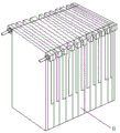
Fig. 5 is a schematic view (a) of the structure of the trough body of the present invention.
Fig. 6 is a schematic view (ii) of the structure of the trough body of the present invention.
The device comprises a tank body structure 1, a side plate 2, a bottom plate 3, a cooling pipe 4, a false bottom 5, an anolyte chamber 6 and a liquid outlet 7.
Detailed Description
The present invention will be described in further detail with reference to examples, but the present invention is not limited thereto.
Example (b):
the embodiment relates to a false-free bottom groove body matched with a diaphragm system assembly.
Different from the structure of the false bottom 5 arranged in the electrolytic cell body in the prior art, the electrolytic cell body without the false bottom 5 is adopted in the embodiment, as shown in the structure of fig. 2, the electrolytic cell body comprises a cell body structure 1 with an open top, the cell body structure 1 is formed by enclosing side plates 2 and a bottom plate 3, and is used in cooperation with an electrolytic device with an anolyte chamber 6 arranged at the bottom, such as a diaphragm system assembly, and the like, and particularly, the two electrolytic devices shown in fig. 3 and fig. 4 can be seen. During the use, with aforementioned electrolytic device direct hoist and mount put into cell body structure 1 can, owing to there is not false end 5 structure, the electrolyte in the cell body structure can fully flow around electrolytic device, consequently, can not block the flow of electrolyte, simultaneously, the positive pole sediment is collected in positive pole liquid chamber 6, can not cause the difficulty of cell body structure 1 clearance.
In this embodiment, the tank body structure 1 can be formed by enclosing four side plates 2 and a bottom plate 3, and when the tank body structure is used in conjunction with an electrolysis device such as a diaphragm system assembly, the cooling pipes 4 can be arranged on the upper and lower inner walls of the side plates 2 due to the structure without the false bottom 5, that is, as shown in fig. 2, the cooling pipes 4 are transversely arranged and are sequentially arranged from the top to the bottom of the tank body structure 1. Or in another embodiment, the cooling pipes 4 are vertically arranged, so that the cooling pipes 4 sequentially extend from the top to the bottom of the tank body structure 1, and the cooling heat exchange area of the electrolytic tank is increased. In the actual production process, the cooling pipes 4 can be arranged according to the requirements of the electrolysis process, for example, the cooling pipes 4 are arranged on the four side plates 2 of the tank body structure 1, or the cooling pipes 4 are arranged on the two side plates 2 which are oppositely arranged on the tank body structure 1, and the like.
In order to facilitate the installation of the cooling pipe 4, the inner wall of the side plate 2 is provided with a mounting bracket for fixing the cooling pipe 4. Of course, to further improve the practicability of the tank body structure 1, in an embodiment, the tank body structure 1 may be made of acid-base-resistant, anti-aging, and high-strength modified plastics or engineering plastics, such as ABS plastics, reinforced polypropylene (PP), and the like. In order to facilitate the cleaning of the tank body structure 1, a liquid outlet 7 is further provided on the tank body structure 1, for example, the liquid outlet 7 is provided on the side plate 2 of the tank body structure 1, and the liquid outlet 7 is provided on two opposite side plates 2 of the tank body structure 1, as shown in fig. 5. Alternatively, a drain port 7 may be provided in the bottom plate 3 of the tank body structure 1 as shown in FIG. 6 (note that FIGS. 5 and 6 are schematic views of the drain port 7, and the cooling pipe 4 is omitted).
The above is only the preferred embodiment of the present invention, not to the limitation of the present invention in any form, all the technical matters of the present invention all fall into the protection scope of the present invention to any simple modification and equivalent change of the above embodiments.
Claims (6)
1. The utility model provides a no false bottom cell body that cooperation diaphragm system assembly used which characterized in that: including open-top's cell body structure (1), cell body structure (1) is enclosed to close by curb plate (2) and bottom plate (3) and forms, establishes cooling tube (4) in curb plate (2) inner wall, and cooling tube (4) are arranged or are extended along cell body structure (1) top to bottom in proper order.
2. The false-free tank body matched with the diaphragm system combination body for use according to claim 1, wherein: the cross section of the groove body structure (1) is rectangular, and the cooling pipes (4) are arranged on four side plates (2) of the groove body structure (1) or two oppositely-arranged side plates (2).
3. The false-free tank body matched with the diaphragm system combination body for use according to claim 1, wherein: and a mounting bracket for fixing the cooling pipe (4) is arranged on the inner wall of the side plate (2).
4. The false-free tank body matched with the diaphragm system combination body for use according to claim 1, wherein: the tank body structure (1) is made of modified plastics or engineering plastics.
5. The false-free tank body matched with the diaphragm system combination body for use according to claim 1, wherein: and a liquid outlet (7) is arranged on the tank body structure (1).
6. The false-free tank body used in cooperation with the diaphragm system combination as claimed in claim 5, wherein: the liquid discharge port (7) is arranged on the side plate (2) or the bottom plate (3).
Priority Applications (1)
| Application Number | Priority Date | Filing Date | Title |
|---|---|---|---|
| CN201921469860.4U CN210529078U (en) | 2019-09-05 | 2019-09-05 | False-bottom-free groove body matched with diaphragm system assembly for use |
Applications Claiming Priority (1)
| Application Number | Priority Date | Filing Date | Title |
|---|---|---|---|
| CN201921469860.4U CN210529078U (en) | 2019-09-05 | 2019-09-05 | False-bottom-free groove body matched with diaphragm system assembly for use |
Publications (1)
| Publication Number | Publication Date |
|---|---|
| CN210529078U true CN210529078U (en) | 2020-05-15 |
Family
ID=70604325
Family Applications (1)
| Application Number | Title | Priority Date | Filing Date |
|---|---|---|---|
| CN201921469860.4U Active CN210529078U (en) | 2019-09-05 | 2019-09-05 | False-bottom-free groove body matched with diaphragm system assembly for use |
Country Status (1)
| Country | Link |
|---|---|
| CN (1) | CN210529078U (en) |
-
2019
- 2019-09-05 CN CN201921469860.4U patent/CN210529078U/en active Active
Similar Documents
| Publication | Publication Date | Title |
|---|---|---|
| CN104528889B (en) | A kind of multiple-unit integrated form electrolysis bath | |
| CN102010035B (en) | Immersed electrolysis mixing device | |
| CN211005660U (en) | Multifunctional diaphragm frame for manganese electrolysis | |
| CN210529078U (en) | False-bottom-free groove body matched with diaphragm system assembly for use | |
| CN101451245A (en) | Dipolar type natural circulation ionic membrane electrolysis unit groove | |
| CN211645405U (en) | Device for preparing hydrogen and oxygen by electrolyzing water | |
| CN204982087U (en) | Copper electrolyte circulating device | |
| CN207047347U (en) | Electrochemical anodic oxidation experimental teaching unit | |
| CN207537543U (en) | For recycling the electrolytic cell of copper | |
| CN211170913U (en) | Water tank and electrolytic bath integrated electrolytic device | |
| CN210464819U (en) | Electrolytic cell diaphragm detection device | |
| CN205115659U (en) | Anode system of plating solution separation | |
| CN103436913B (en) | The device of a kind of electro deposited nickel or electrodeposited cobalt | |
| CN203451635U (en) | Electrolysis unit and overflow electrolysis device | |
| CN210367936U (en) | Integrated electrolytic cell device | |
| CN208472197U (en) | Thick indium impurity removing equipment | |
| CN214115738U (en) | Diaphragm frame device for electrolytic manganese diaphragm electrolysis method | |
| CN202039131U (en) | Immersed electrolyzing mixing device | |
| CN207031039U (en) | Three casees anionic membrane electrolysis units of ammonium chloride waste-water are handled for being electrolysed | |
| CN214636295U (en) | Plasma equipment | |
| CN202323064U (en) | Equipment for removing metal impurities in chromeplate solution | |
| CN105350063B (en) | A kind of anode system of electroplate liquid separation | |
| CN204727968U (en) | A kind of electric deposition device | |
| CN101748429B (en) | Metal manganese electrolytic bath for improving current efficiency and preventing crystallization | |
| CN220079218U (en) | Electrolytic tank with double chlorine gas collecting hood structure |
Legal Events
| Date | Code | Title | Description |
|---|---|---|---|
| GR01 | Patent grant | ||
| GR01 | Patent grant |