CN210450081U - Leading belt cleaning device is used to pseudo-ginseng - Google Patents
Leading belt cleaning device is used to pseudo-ginseng Download PDFInfo
- Publication number
- CN210450081U CN210450081U CN201921371689.3U CN201921371689U CN210450081U CN 210450081 U CN210450081 U CN 210450081U CN 201921371689 U CN201921371689 U CN 201921371689U CN 210450081 U CN210450081 U CN 210450081U
- Authority
- CN
- China
- Prior art keywords
- soaking
- pseudo
- ginseng
- cylinder
- filter plate
- Prior art date
- Legal status (The legal status is an assumption and is not a legal conclusion. Google has not performed a legal analysis and makes no representation as to the accuracy of the status listed.)
- Active
Links
Images


Abstract
The utility model discloses a leading belt cleaning device for pseudo-ginseng, including track and open-topped soaking jar, linear slip is provided with two soaking jars side by side on the track, the bottom of soaking jar is provided with agitating unit and the drain pipe that has the valve, one side of soaking jar slides and is provided with the lift baffle, one side of lift baffle is provided with the elevating gear that drives the lift baffle and go up and down; a filter plate is arranged in the soaking cylinder above the stirring device, one end of the filter plate, which is far away from the lifting baffle, is hinged to the inner side of the soaking cylinder, and a rotating device for driving the filter plate to rotate around the hinged position is arranged on one side of the filter plate; the utility model discloses feeding, washing, the ejection of compact of pseudo-ginseng are synchronous parallel has, effectively improve the cleaning efficiency, effectively clear away the most earth on pseudo-ginseng surface, effectively soften the earth in turning and the gap on pseudo-ginseng surface, the follow-up abluent beneficial effect of the pseudo-ginseng of being convenient for.
Description
Technical Field
The utility model belongs to the technical field of chinese herbal medicine cleaning equipment, concretely relates to leading belt cleaning device is used to pseudo-ginseng.
Background
Pseudo-ginseng is a commonly used medicinal material in the field of traditional Chinese medicine in China, and in order to be convenient to take, the pseudo-ginseng is usually processed into a sheet shape or a powder shape at present, and before the sheet shape or the powder shape of the pseudo-ginseng is processed, the pseudo-ginseng needs to be cleaned, dried and the like. At present, the pseudo-ginseng conveying line is provided with a plurality of spray heads, and the spray heads spray water to clean and remove soil and gravel on the surface of the pseudo-ginseng while transporting the pseudo-ginseng. However, since the shapes of the pseudo-ginseng are extremely irregular, a large amount of soil and gravels are generally adhered to the surface of the pseudo-ginseng, and the soil and gravels accumulated at corners and gaps of the surface of the pseudo-ginseng are difficult to remove only by means of water spraying, which results in the disadvantage that the conventional pseudo-ginseng cleaning method by means of water spraying is not thorough in cleaning. In order to effectively remove soil and gravels attached to the surfaces of the pseudo-ginseng, the pseudo-ginseng needs to be soaked in advance before being subjected to water-jet cleaning so as to soften the soil and the gravels on the surfaces of the pseudo-ginseng. The existing soaking device usually carries out the feeding, soaking and discharging of the pseudo-ginseng in a soaking pool, and the actual working efficiency is low. Therefore, to the problem that the cleanness that traditional pseudo-ginseng belt cleaning device exists is not thorough, clean inefficiency, the utility model discloses a leading belt cleaning device is used to pseudo-ginseng.
SUMMERY OF THE UTILITY MODEL
An object of the utility model is to provide a leading belt cleaning device is used to pseudo-ginseng realizes carrying out the washing, feeding and the ejection of compact of pseudo-ginseng in step, fully soaks the pseudo-ginseng simultaneously, when getting rid of the most earth in pseudo-ginseng surface, effectively softens the earth in pseudo-ginseng surface turning and the gap, is convenient for thoroughly get rid of the earth on pseudo-ginseng surface in follow-up cleaning process.
The utility model discloses a following technical scheme realizes:
a front cleaning device for pseudo-ginseng comprises a rail and soaking cylinders with openings at the tops, wherein two soaking cylinders are arranged side by side in a linear sliding mode on the rail, a stirring device and a drain pipe with a valve are arranged at the bottom of each soaking cylinder, a lifting baffle is arranged on one side of each soaking cylinder, and a lifting device for driving the lifting baffle to lift is arranged on one side of each lifting baffle; the inner part of the soaking cylinder is provided with a filter plate above the stirring device, one end of the filter plate, which is far away from the lifting baffle, is hinged on the inner side of the soaking cylinder, and one side of the filter plate is provided with a rotating device which drives the filter plate to rotate around the hinged part.
The working principle is as follows:
the track includes that two parallels align to set up the single track subaerial, and the linear slip is provided with two soaking cylinders along orbital trend on the track, and two soaking cylinders set up side by side along orbital trend. The length of the track is more than or equal to the length of the three soaking cylinders in parallel, the track is uniformly divided into a working station in the middle and preparation stations on two sides of the working station along the track, and external water inlet pipes are arranged at positions corresponding to the working station and the two preparation stations. Placing unwashed pseudo-ginseng into the inside of soaking cylinder from the top opening of soaking cylinder, then moving two soaking cylinders along track linearity, make one of them soaking cylinder be located the work station, another soaking cylinder is located the preparation station this moment, then through the water injection pipe to the soaking cylinder that is located the work station, open agitating unit simultaneously and stir the pseudo-ginseng in the soaking cylinder, effectively soften the earth and the grit that bond on the pseudo-ginseng, can clear away the most earth and the grit on pseudo-ginseng surface simultaneously, effectively guarantee follow-up secondary cleaning's to the pseudo-ginseng effect. After the pseudo-ginseng is soaked for a period of time, most of soil and gravels on the surface of the pseudo-ginseng are removed or softened, at the moment, a drain pipe at the bottom of the soaking cylinder is opened, and sewage with the soil and the gravels is discharged. Meanwhile, one end, close to the lifting baffle, of the filter plate at the bottom of the soaking cylinder is in a tilting state, namely one end, close to the lifting baffle, of the filter plate is higher than one end, close to the inner wall of the soaking cylinder, of the filter plate. At the moment, the water inlet pipe is opened again to inject water into the soaking cylinder, meanwhile, the water discharge pipe is kept in an opened state, residual soil and sand and gravel on the inner wall of the soaking cylinder and the filter plate are removed through flowing water flow, when water discharged by the water discharge pipe is clean, the filter plate is driven to rotate through the rotating device until one end, close to the lifting baffle, of the filter plate is lower than one end, close to the inner wall of the soaking cylinder, of the filter plate, the filter plate inclines towards the lifting baffle at the moment, then the lifting baffle is driven to ascend through the lifting device, the cleaned pseudo-ginseng slides out of the soaking cylinder from the opening of the lifting baffle along the inclined plane of the filter plate to be subsequently cleaned, and then the lifting baffle descends. Then the two soaking cylinders move linearly along the rail, the empty soaking cylinder is moved to a preparation station, the other soaking cylinder filled with the pseudo-ginseng is moved to a working station, then the empty soaking cylinder at the preparation station is cleaned again and fed with the pseudo-ginseng, and the soaking cylinder filled with the pseudo-ginseng at the working station is cleaned by soaking according to the steps, so that the pseudo-ginseng can be cleaned circularly.
In order to better realize the utility model, the rotating device further comprises a rotating shaft, shaft sleeves, a rotating speed reducer and a rotating motor, the shaft sleeves are arranged at two sides of the interior of the soaking cylinder, two ends of the rotating shaft are respectively and rotatably arranged in the shaft sleeves at two sides, one end of the rotating shaft penetrates through the soaking cylinder and extends to the outer side of the soaking cylinder, and the side surface of the rotating shaft is connected with one side of the filter plate; the one end that the pivot extends to the soaking cylinder outside is connected with the output of rotating the speed reducer, the input of rotating the speed reducer is connected with the output that rotates the motor.
The rotating motor and the rotating speed reducer are installed on the outer side of the soaking cylinder through the installation frame, and the rotating speed reducer can effectively increase the torque output by the rotating motor, so that the rotating motor drives the rotating shaft to rotate more stably. Meanwhile, the rotating speed reducer has a self-locking function, so that the rotating shaft is prevented from rotating automatically when the filter plate bears the weight of the pseudo-ginseng. The position of the rotating shaft penetrating through the soaking cylinder is provided with a sealing element, so that the water inside the soaking cylinder is prevented from leaking.
For better realization the utility model discloses, furtherly, arc draw-in groove has been seted up along circumference on the axle sleeve, the outside of pivot is provided with the stopper, and the stopper slides and sets up the inside at arc draw-in groove.
The filter plate only carries out the swing of certain angle in the inside of soaking cylinder to do not carry out the circumference of three hundred sixty degrees and rotate, consequently, the arc draw-in groove of corresponding angle is seted up on the axle sleeve to the turned angle who corresponds the filter plate, the outside of pivot is provided with the stopper, the stopper slides and sets up the inside at the arc draw-in groove, it slides along the arc spout to drive the stopper when the pivot rotates, it is spacing to be blocked by the arc wall when the end position of stopper slip to the arc wall, the pivot can not continue to rotate this moment, the filter plate can not continue to rotate promptly. The two ends of the limiting block at the arc-shaped groove respectively correspond to two limit positions of the filter plate in the soaking cylinder, and the two limit positions are respectively an upward inclined position and a downward inclined position of the filter plate close to the lifting baffle.
In order to better realize the utility model, the lifting device further comprises guide posts, guide sleeves and a lifting cylinder, the guide posts are arranged on two sides of the top of the soaking cylinder, the guide sleeves are arranged on two sides of the top of the lifting baffle, and the guide sleeves are sleeved on the guide posts in a sliding manner; the lifting cylinder is arranged on two sides of the top of the soaking cylinder, and the lifting end of the lifting cylinder is connected with one side of the lifting baffle.
Both ends of one side of the soaking cylinder are provided with sliding grooves along the vertical direction, and both ends of the lifting baffle are respectively arranged in the sliding grooves in a sliding manner. The lifting end of the lifting cylinder drives the lifting baffle to lift along the sliding groove in the vertical direction, and the soaking cylinder is opened when the lifting baffle is lifted, so that the pseudo-ginseng can conveniently slide out of the soaking cylinder; the soaking cylinder is closed when the lifting baffle descends. When the lifting baffle goes up and down, the guide sleeve slides along the guide column along with the lifting baffle going up and down to guide the lifting baffle going up and down.
For better realization the utility model discloses, furtherly, agitating unit includes (mixing) shaft, stirring fan blade, agitator motor, the (mixing) shaft runs through and rotates the bottom that sets up at the soaking cylinder, the (mixing) shaft is located the inside one end cover of soaking cylinder and is equipped with stirring fan blade, the (mixing) shaft is located the one end in the soaking pole outside and is connected with agitator motor's output.
Stirring motor drives the (mixing) shaft and rotates, and the (mixing) shaft then drives stirring fan blade and rotates in the inside of soaking cylinder, and stirring fan blade rotates and then drives the inside moisture rotation of soaking cylinder, effectively clears away the earth and the grit that pseudo-ginseng surface bonded through the rotation of rivers.
In order to better realize the utility model, furthermore, the junction of the stirring shaft and the soaking cylinder is provided with a sealing element.
In order to better realize the utility model discloses, furtherly, still include linear drive and wheel components, the soaking cylinder passes through the wheel components roll and sets up on the track, the bottom of soaking cylinder still is provided with and is used for driving the wheel components along the rolling linear drive of track.
For better realization the utility model discloses, furtherly, orbital both ends are provided with the spacing riser of station.
The station limiting vertical plates at the two ends of the rail limit the two side-by-side soaking cylinders at the working station and the preparation station respectively, so that the soaking cylinders are prevented from moving over the rail.
In order to better realize the utility model discloses, furtherly, be provided with the brush on the inner wall of soaking jar.
When pseudo-ginseng inside the soaking jar rotates along with rivers synchronous, the surface of pseudo-ginseng can contact with the brush on the soaking jar inner wall, and then clears away the earth and the grit on pseudo-ginseng surface.
Compared with the prior art, the utility model, following advantage and beneficial effect have:
(1) the utility model discloses a set up two soaking jars side by side along the track trend on the track, and through linear drive arrangement drive two soaking jars along the track reciprocating motion between work station and preparation station, realize that one soaking jar carries out the pseudo-ginseng and washs and the work of ejection of compact at work station, another soaking jar carries out the feeding operation in preparation station synchronization, has effectively improved pseudo-ginseng and has washd efficiency;
(2) the utility model has the advantages that the lifting baffle is arranged on one side of the soaking cylinder, and the lifting baffle is driven by the lifting device to lift, when cleaning the pseudo-ginseng, the lifting baffle falls to seal the soaking cylinder, and the lifting baffle rises during discharging to open the soaking cylinder, thereby having the beneficial effects of continuous and convenient cleaning and discharging of the pseudo-ginseng;
(3) the utility model has the advantages that the filter plate is hinged in the soaking cylinder, and the rotating device drives the filter plate to rotate by a moving angle, so that when the pseudo-ginseng is cleaned, the rotating device drives the filter plate to rotate to a tilted state, and the earth is more easily settled along the filter plate; when the pseudo-ginseng is discharged, the rotating device drives the filter plate to rotate to a state of inclining towards the lifting baffle plate, so that the pseudo-ginseng can conveniently and quickly slide out of the soaking cylinder along the filter plate;
(4) the utility model discloses a bottom at the soaking cylinder sets up agitating unit, stirs the rivers in the soaking cylinder through agitating unit, and then effectively clears away the most earth on pseudo-ginseng surface through rotatory rivers to soften the earth in pseudo-ginseng surface turning and the gap.
Drawings
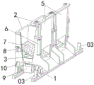
Fig. 1 is a schematic view of the overall structure of the present invention;
fig. 2 is a schematic view of the back structure of the present invention;
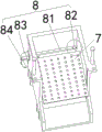
FIG. 3 is a schematic structural view of a rotating device;
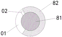
FIG. 4 is an enlarged view of a portion of FIG. 3;
FIG. 5 is a cross-sectional view of FIG. 4;
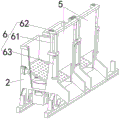
FIG. 6 is a schematic structural view of the lifting device;
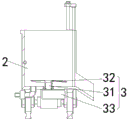
fig. 7 is a schematic structural view of the stirring device.
Wherein: 1-a track; 2-soaking the vat; 3-a stirring device; 4-a drain pipe; 5, lifting a baffle plate; 6-a lifting device; 7-a filter plate; 8-a rotating device; 9-a linear drive; 10-a roller assembly; 31-a stirring shaft; 32-stirring fan blades; 33-a stirring motor; 61-a guide post; 62-a guide sleeve; 63-a lifting cylinder; 81-a rotating shaft; 82-shaft sleeve; 83-rotating speed reducer; 84-a rotating motor; 01-arc clamping groove; 02-a limiting block; 03-limit vertical plate.
Detailed Description
Example 1:
the front cleaning device for panax notoginseng comprises a track 1 and a soaking cylinder 2 with an open top, as shown in fig. 1 and fig. 2, the track 1 is provided with two soaking cylinders 2 side by side in a linear sliding manner, the bottom of the soaking cylinder 2 is provided with a stirring device 3 and a drain pipe 4 with a valve, one side of the soaking cylinder 2 is provided with a lifting baffle plate 5 in a sliding manner, and one side of the lifting baffle plate 5 is provided with a lifting device 6 for driving the lifting baffle plate 5 to lift; a filter plate 7 is arranged above the stirring device 3 in the soaking cylinder 2, one end of the filter plate 7, which is far away from the lifting baffle 5, is hinged to the inner side of the soaking cylinder 2, and a rotating device 8 for driving the filter plate 7 to rotate around the hinged position is arranged on one side of the filter plate 7.
Two soaking cylinders 2 are arranged on the track 1 in a side-by-side linear sliding mode along the trend of the track 1, and adjacent soaking cylinders 2 are connected through welded connection channel steel. The track 1 is divided into three stations along length direction, is the workstation that is located the centre and is located the preparation station of workstation both sides respectively, and when the steeping jar 2 that sets up side by side moved along track 1 linearity, can realize reciprocating motion between workstation and preparation station, and when one of them steeping jar 2 was located workstation, another steeping jar 2 was located and prepares the station certainly.
The lifting baffle 5 positioned at one side of the soaking cylinder 2 of the working station is in a descending state to seal the soaking cylinder 2, at the moment, the unwashed pseudo-ginseng is put into the soaking cylinder 2 from the opening at the top of the soaking cylinder 2, meanwhile, water is injected into the soaking cylinder 2 through an external water inlet pipe, then the stirring device 3 positioned at the bottom of the soaking cylinder 2 is started, the stirring device 3 drives the water flow in the soaking cylinder 2 to rotate, and further most of soil and gravel bonded on the surface of the pseudo-ginseng are softened and removed, when pseudo-ginseng is soaked, one end of the filter plate 7 in the soaking cylinder 2, which is close to the lifting baffle 5, is higher than the hinged end of the filter plate 7 and the soaking cylinder 2, that is, the filter plate 7 is in an upward tilting state during soaking, and at this time, soil and gravel falling off from the pseudo-ginseng are deposited to one end of the filter plate 7 hinged with the inside of the soaking cylinder 2 along the inclination angle of the filter plate 7, and continue to be deposited downwards through the filter holes on the filter plate 7. After pseudo-ginseng soaking and cleaning are completed, an electromagnetic valve on a drain pipe 4 at the bottom of a soaking cylinder 2 is opened, sewage is discharged from the soaking cylinder 2, a water inlet pipe is opened to synchronously inject water into the soaking cylinder 2 while discharging water, soil and gravels attached to the inner wall of the soaking cylinder 2 are further cleaned, the filter plate 7 is driven to swing by a rotating device 8 for a certain angle until the sewage discharged from the drain pipe 4 is relatively clean, one end, close to the lifting baffle plate 5, of the filter plate 7 is lower than one end, hinged to the inside of the soaking cylinder 2, of the filter plate 7, namely, the filter plate 7 is in a downward-inclined state, then the lifting baffle plate 5 is driven to rise by a lifting device 6, the side face of the soaking cylinder 2 is opened, and the cleaned pseudo-ginseng slides to the outside of the soaking cylinder 2 along the. And then the two soaking cylinders 2 linearly move along the rail 1, so that the vacant soaking cylinders 2 move to a preparation station for feeding, the other soaking cylinder 2 filled with the pseudo-ginseng moves to a working station for pseudo-ginseng cleaning according to the steps, the soaking cylinders 2 are driven to reciprocate between the working station and the preparation station, one soaking cylinder 2 is used for cleaning the pseudo-ginseng, and the other soaking cylinder 2 is used for feeding, so that the cyclic feeding and cleaning of the pseudo-ginseng are finally realized.
In order to avoid interference between the filter plate 7 and the inner wall of the lifting baffle 5 when the filter plate 7 rotates, a flexible rubber transition block is arranged at one end of the filter plate 7 close to the lifting baffle 5, the rubber transition block ensures that the filter plate 7 is tightly attached to the inner side of the lifting baffle 5 without a gap, and pseudo-ginseng is prevented from falling below the filter plate 7 from the gap; meanwhile, when the filter plate 7 swings, the rubber transition block can be compressed and deformed, and the interference between the filter plate 7 and the lifting baffle 5 is avoided.
Meanwhile, in order to ensure that the pseudo-ginseng does not scatter when sliding out of the soaking cylinder 2, a downward-inclined discharge hopper is arranged at the bottom of the side opening of the soaking cylinder 2.
Example 2:
the embodiment is further optimized on the basis of embodiment 1, as shown in fig. 3, the rotating device 8 includes a rotating shaft 81, shaft sleeves 82, a rotating speed reducer 83, and a rotating motor 84, the shaft sleeves 82 are disposed at two sides inside the soaking cylinder 2, two ends of the rotating shaft 81 are respectively rotatably mounted inside the shaft sleeves 82 at two sides, one end of the rotating shaft 81 penetrates through the soaking cylinder 2 and extends to the outside of the soaking cylinder 2, and a side surface of the rotating shaft 81 is connected with one side of the filter plate 7; one end of the rotating shaft 81 extending to the outer side of the soaking cylinder 2 is connected with the output end of the rotating speed reducer 83, and the input end of the rotating speed reducer 83 is connected with the output end of the rotating motor 84.
The rotating motor 84 and the rotating speed reducer 83 are mounted on the outer side of the soaking cylinder 2 through mounting frames, and the rotating speed reducer 83 can effectively increase the torque output by the rotating motor 84, so that the rotating motor 84 drives the rotating shaft 81 to rotate more stably. Meanwhile, the rotation speed reducer 83 should have a self-locking function, so as to prevent the filter plate 7 from driving the rotating shaft 81 to rotate when bearing the weight of the pseudo-ginseng. The rotating shaft 81 penetrates through the soaking cylinder 2 to be provided with a sealing element, so that the water inside the soaking cylinder is prevented from leaking.
A sleeve is arranged on one side of the filter plate 7 close to the rotating shaft 81, the rotating shaft 81 is inserted into the sleeve, and the fixed connection between one side of the filter plate 7 and the outer side surface of the rotating shaft 81 is realized through welding or a locking pin, so that the filter plate 7 can rotate along with the rotating shaft 81.
Other parts of this embodiment are the same as embodiment 1, and thus are not described again.
Example 3:
this embodiment is further optimized on the basis of above-mentioned embodiment 1 or 2, as shown in fig. 4 and fig. 5, an arc-shaped slot 01 is provided along the circumference on the shaft sleeve 82, a limiting block 02 is provided on the outer side of the rotating shaft 81, and the limiting block 02 is slidably disposed inside the arc-shaped slot 01.
The central angle degree corresponding to the arc-shaped clamping groove 01 is equal to the swinging angle of the filter plate 7, and the central angle degree of the arc-shaped clamping groove 01 is set to be 45 degrees.
Be provided with stopper 02 on the lateral surface of pivot 81, stopper 02 is located the inside of arc draw-in groove 01, when stopper 02 rotates along with pivot 81, when stopper 02 rotates to the end extreme position of arc draw-in groove 01, stopper 02 receives the spacing of arc draw-in groove 01 end, stopper 02 can not continue to rotate this moment, and pivot 81 can not continue to rotate promptly, realizes the restriction to the turned angle of pivot 81, further realizes the restriction to the turned angle of filter plate 7. The limiting blocks 02 are at the extreme positions of the two ends of the arc-shaped clamping groove 01, namely, at the positions of tilting and downward inclination corresponding to one ends of the filter plates 7 close to the lifting baffle 5.
The rest of this embodiment is the same as embodiment 1 or 2, and therefore, the description thereof is omitted.
Example 4:
the embodiment is further optimized on the basis of any one of the above embodiments 1 to 3, as shown in fig. 6, the lifting device 6 includes guide posts 61, guide sleeves 62, and a lifting cylinder 63, the guide posts 61 are disposed on both sides of the top of the soaking cylinder 2, the guide sleeves 62 are disposed on both sides of the top of the lifting baffle 5, and the guide sleeves 62 are slidably sleeved on the guide posts 61; the lifting cylinders 63 are arranged on two sides of the top of the soaking cylinder 2, and the lifting ends of the lifting cylinders 63 are connected with one side of the lifting baffle 5.
The guide posts 61 are arranged on two sides of the top of the soaking cylinder 2 close to the lifting baffle 5, through holes for the guide posts 61 to pass through are coaxially formed in two ends of the top of the lifting baffle 5 corresponding to the two guide posts 61 respectively, guide sleeves 62 are coaxially arranged in the through holes, and the guide sleeves 62 are sleeved on the outer sides of the guide posts 61 and can slide along the guide posts 61. The lift end of the lift cylinder 63 of both sides drives the both ends at the top of lifting baffle 5 respectively and goes up and down in step, and guide post 61 and uide bushing 62 lead lifting baffle 5 simultaneously, avoid lifting baffle 5's the lift appearance card pause.
The lifting cylinder 63 in the lifting device 6 can be replaced by devices or structures such as an oil cylinder, a gear rack group, a screw lifting group and the like.
Other parts of this embodiment are the same as any of embodiments 1 to 3, and thus are not described again.
Example 5:
this embodiment is further optimized on the basis of any one of the above embodiments 1-4, as shown in fig. 7, the stirring device 3 includes a stirring shaft 31, stirring blades 32, and a stirring motor 33, the stirring shaft 31 is rotatably disposed at the bottom of the soaking tank 2, the stirring blades 32 are sleeved at one end of the stirring shaft 31 located inside the soaking tank 2, and one end of the stirring shaft 31 located outside the soaking rod 2 is connected to an output end of the stirring motor 33.
The bottom of the soaking cylinder 2 is provided with a mounting hole, a stirring shaft 31 is rotatably arranged in the mounting hole through a bearing, and a sealing ring is arranged between the outer side surface of the stirring shaft 31 and the hole wall of the mounting hole for sealing. One end of the stirring shaft 31 extends to the inside of the soaking cylinder 2 and is sleeved with a stirring fan blade 32, and the other end of the stirring shaft 31 extends to the outside of the soaking cylinder 2 and is connected with the output end of a stirring motor 33. The stirring motor 33 drives the stirring shaft 31 to rotate, and further drives the stirring fan blades 32 to rotate, so as to stir the moisture inside the soaking cylinder 2.
Other parts of this embodiment are the same as any of embodiments 1 to 4, and thus are not described again.
Example 6:
this embodiment is further optimized on the basis of any one of the above embodiments 1 to 5, and a sealing member is disposed at the connection position of the stirring shaft 31 and the soaking cylinder 2.
Other parts of this embodiment are the same as any of embodiments 1 to 5, and thus are not described again.
Example 7:
the present embodiment is further optimized on the basis of any one of the above embodiments 1-6, as shown in fig. 1, further comprising a linear driving device 9 and a roller assembly 10, wherein the soaking tank 2 is arranged on the rail 1 by rolling the roller assembly 10, and the bottom of the soaking tank 2 is further provided with the linear driving device 9 for driving the roller assembly 10 to roll along the rail 1.
The roller assembly 10 comprises a roller, a roller shaft and a roller bearing, wherein the four corners of the bottom of the soaking cylinder 2 are provided with mounting feet, the mounting feet are provided with mounting holes, the roller shaft is rotatably mounted in the mounting holes through the roller bearing, and the roller shaft is sleeved with the roller. The roller shafts are connected with the output end of the linear driving device 9, the linear driving device 9 is a bidirectional output motor, the end heads of the roller shafts on the two sides are respectively connected with the output holes on the two sides of the bidirectional output motor, the roller shafts on the two sides are synchronously driven to rotate through the bidirectional output motor, the roller is further driven to rotate, and the soaking cylinder 2 is driven to linearly move along the track 1.
Other parts of this embodiment are the same as any of embodiments 1 to 6, and thus are not described again.
Example 8:
this embodiment is further optimized on the basis of any one of the above embodiments 1 to 7, and as shown in fig. 1, the two ends of the rail 1 are provided with the station-limiting vertical plates 03.
In order to prevent the soaking cylinders 2 from sliding out of the rail 1 or moving over the position, the two ends of the rail 1 are provided with the station limiting vertical plates 03, when the roller rolls to the position of the station limiting vertical plates 03, the station limiting vertical plates 03 limit the roller, the roller cannot continue to roll at the moment, namely, the soaking cylinders 2 cannot continue to move along the rail 1, when the two soaking cylinders 2 are limited, one station limiting cylinder 2 is located at a working station, and the other soaking cylinder 2 is located at a position for preparing the station.
Other parts of this embodiment are the same as any of embodiments 1 to 7, and thus are not described again.
Example 9:
this embodiment is further optimized on the basis of any one of the above embodiments 1 to 8, and the inner wall of the soaking cylinder 2 is provided with a brush.
The inner wall of the soaking cylinder 2 above the filter plate 7 is provided with a brush, when cleaning the pseudo-ginseng, the surface of the pseudo-ginseng rotating along with water flow can contact with the brush, and soil and sand on the surface of the pseudo-ginseng are further removed through the brush.
Other parts of this embodiment are the same as any of embodiments 1 to 8, and thus are not described again.
The above is only the preferred embodiment of the present invention, not to the limitation of the present invention in any form, all the technical matters of the present invention all fall into the protection scope of the present invention to any simple modification and equivalent change of the above embodiments.
Claims (9)
1. A front cleaning device for pseudo-ginseng comprises a rail (1) and soaking cylinders (2) with openings at the tops, and is characterized in that the rail (1) is provided with two soaking cylinders (2) side by side in a linear sliding manner, the bottoms of the soaking cylinders (2) are provided with a stirring device (3) and a drain pipe (4) with a valve, one side of each soaking cylinder (2) is provided with a lifting baffle (5), and one side of each lifting baffle (5) is provided with a lifting device (6) for driving the lifting baffle (5) to lift; the improved soaking device is characterized in that a filter plate (7) is arranged above the stirring device (3) in the soaking cylinder (2), one end, far away from the lifting baffle (5), of the filter plate (7) is hinged to the inner side of the soaking cylinder (2), and a rotating device (8) for driving the filter plate (7) to rotate around the hinged position is arranged on one side of the filter plate (7).
2. The prepositive cleaning device for pseudo-ginseng according to claim 1, wherein the rotating device (8) comprises a rotating shaft (81), shaft sleeves (82), a rotating speed reducer (83) and a rotating motor (84), the shaft sleeves (82) are arranged at two sides of the inside of the soaking cylinder (2), two ends of the rotating shaft (81) are respectively and rotatably arranged in the shaft sleeves (82) at two sides, one end of the rotating shaft (81) penetrates through the soaking cylinder (2) and extends to the outside of the soaking cylinder (2), and the side surface of the rotating shaft (81) is connected with one side of the filter plate (7); the one end that pivot (81) extended to the soaking cylinder (2) outside is connected with the output that rotates speed reducer (83), the input that rotates speed reducer (83) is connected with the output that rotates motor (84).
3. The front cleaning device for panax notoginseng according to claim 2, wherein an arc-shaped slot (01) is formed in the shaft sleeve (82) along the circumferential direction, a limiting block (02) is arranged on the outer side of the rotating shaft (81), and the limiting block (02) is slidably arranged inside the arc-shaped slot (01).
4. The front cleaning device for panax notoginseng according to any one of claims 1 to 3, wherein the lifting device (6) comprises guide posts (61), guide sleeves (62) and a lifting cylinder (63), the guide posts (61) are arranged on two sides of the top of the soaking cylinder (2), the guide sleeves (62) are arranged on two sides of the top of the lifting baffle plate (5), and the guide sleeves (62) are slidably sleeved on the guide posts (61); the lifting cylinders (63) are arranged on two sides of the top of the soaking cylinder (2), and the lifting ends of the lifting cylinders (63) are connected with one side of the lifting baffle (5).
5. The front cleaning device for panax notoginseng according to any one of claims 1 to 3, wherein the stirring device (3) comprises a stirring shaft (31), stirring blades (32) and a stirring motor (33), the stirring shaft (31) is rotatably disposed at the bottom of the soaking tank (2), the stirring blades (32) are sleeved at one end of the stirring shaft (31) located inside the soaking tank (2), and one end of the stirring shaft (31) located outside the soaking tank (2) is connected with the output end of the stirring motor (33).
6. The prepositive cleaning device for panax notoginseng according to claim 5, characterized in that a sealing element is arranged at the joint of the stirring shaft (31) and the soaking cylinder (2).
7. The front cleaning device for panax notoginseng according to claim 1, further comprising a linear driving device (9) and a roller assembly (10), wherein the soaking tank (2) is arranged on the rail (1) in a rolling manner through the roller assembly (10), and the bottom of the soaking tank (2) is further provided with the linear driving device (9) for driving the roller assembly (10) to roll along the rail (1).
8. The front cleaning device for pseudo-ginseng according to claim 7, wherein two ends of the rail (1) are provided with station limiting vertical plates (03).
9. The front cleaning device for panax notoginseng according to claim 1, wherein the inner wall of the soaking cylinder (2) is provided with a brush.
Priority Applications (1)
| Application Number | Priority Date | Filing Date | Title |
|---|---|---|---|
| CN201921371689.3U CN210450081U (en) | 2019-08-22 | 2019-08-22 | Leading belt cleaning device is used to pseudo-ginseng |
Applications Claiming Priority (1)
| Application Number | Priority Date | Filing Date | Title |
|---|---|---|---|
| CN201921371689.3U CN210450081U (en) | 2019-08-22 | 2019-08-22 | Leading belt cleaning device is used to pseudo-ginseng |
Publications (1)
| Publication Number | Publication Date |
|---|---|
| CN210450081U true CN210450081U (en) | 2020-05-05 |
Family
ID=70453137
Family Applications (1)
| Application Number | Title | Priority Date | Filing Date |
|---|---|---|---|
| CN201921371689.3U Active CN210450081U (en) | 2019-08-22 | 2019-08-22 | Leading belt cleaning device is used to pseudo-ginseng |
Country Status (1)
| Country | Link |
|---|---|
| CN (1) | CN210450081U (en) |
Cited By (1)
| Publication number | Priority date | Publication date | Assignee | Title |
|---|---|---|---|---|
| CN112170299A (en) * | 2020-09-25 | 2021-01-05 | 李栋 | Belt cleaning device is used in shrimp processing |
-
2019
- 2019-08-22 CN CN201921371689.3U patent/CN210450081U/en active Active
Cited By (1)
| Publication number | Priority date | Publication date | Assignee | Title |
|---|---|---|---|---|
| CN112170299A (en) * | 2020-09-25 | 2021-01-05 | 李栋 | Belt cleaning device is used in shrimp processing |
Similar Documents
| Publication | Publication Date | Title |
|---|---|---|
| CN211027430U (en) | Biological test tube cleaning device | |
| CN210450081U (en) | Leading belt cleaning device is used to pseudo-ginseng | |
| CN109107949A (en) | A kind of efficient log washer of ore | |
| CN211074180U (en) | Dust removal device of stirrer | |
| CN107597707A (en) | cleaning device for Chinese herbal medicine | |
| CN211515364U (en) | Belt cleaning device is used in medicinal material processing | |
| CN111252568A (en) | Barreled agglomerated sludge unloading device | |
| CN210286721U (en) | Rotary type tank cleaning machine | |
| CN113843095A (en) | Surface treatment device for gloves | |
| CN113351634A (en) | Mixed type heavily pollutes place refuse treatment and soil restoration and uses equipment | |
| CN208102412U (en) | A kind of coating filling machine | |
| CN207187229U (en) | A kind of pear syrup condensed cream filter | |
| CN107159623A (en) | A kind of cleaning equipment for root drug material | |
| CN111333285A (en) | Barreled pharmaceutical sludge automatic treatment system | |
| CN113617270B (en) | Preparation device of nano fluid | |
| CN106091840B (en) | Unpacking propellant bottle placer | |
| CN209476052U (en) | A kind of refractory material inhibits the agitating device of dust leakage | |
| CN110142150B (en) | Sesame sieving mechanism | |
| CN209287849U (en) | A kind of rubber cork rinsing machine | |
| CN208791612U (en) | A kind of probiotics fermention tank | |
| CN207076371U (en) | A kind of sauce agitating device | |
| CN208288548U (en) | A kind of cleaning device for nanometer calcium carbonate preparation | |
| CN213537306U (en) | Film grid with slag discharging device | |
| CN210417053U (en) | Liquid cosmetics filter filling equipment | |
| CN206597737U (en) | A kind of mineral aggregate powder dust separating device |
Legal Events
| Date | Code | Title | Description |
|---|---|---|---|
| GR01 | Patent grant | ||
| GR01 | Patent grant | ||
| CP01 | Change in the name or title of a patent holder |
Address after: 611830 floor 2, building 8, No. 618, Yanhua Road, Dujiangyan Economic Development Zone, Dujiangyan, Chengdu, Sichuan Patentee after: Sichuan yixiangkang Pharmaceutical Co.,Ltd. Address before: 611830 floor 2, building 8, No. 618, Yanhua Road, Dujiangyan Economic Development Zone, Dujiangyan, Chengdu, Sichuan Patentee before: SICHUAN TONGZHENGTANG CHINESE HERBAL PIECES CO.,LTD. |
|
| CP01 | Change in the name or title of a patent holder |