CN210372054U - Telescopic butterfly valve - Google Patents
Telescopic butterfly valve Download PDFInfo
- Publication number
- CN210372054U CN210372054U CN201921054251.2U CN201921054251U CN210372054U CN 210372054 U CN210372054 U CN 210372054U CN 201921054251 U CN201921054251 U CN 201921054251U CN 210372054 U CN210372054 U CN 210372054U
- Authority
- CN
- China
- Prior art keywords
- telescopic
- valve
- plate
- screw
- valve body
- Prior art date
- Legal status (The legal status is an assumption and is not a legal conclusion. Google has not performed a legal analysis and makes no representation as to the accuracy of the status listed.)
- Expired - Fee Related
Links
- 238000007789 sealing Methods 0.000 claims abstract description 92
- 210000004907 gland Anatomy 0.000 claims abstract description 47
- 238000010030 laminating Methods 0.000 claims abstract 4
- 230000006978 adaptation Effects 0.000 claims abstract 2
- 230000000694 effects Effects 0.000 abstract description 3
- 238000009434 installation Methods 0.000 description 4
- 210000005069 ears Anatomy 0.000 description 2
- 230000013011 mating Effects 0.000 description 2
- 230000002265 prevention Effects 0.000 description 2
- 238000010079 rubber tapping Methods 0.000 description 2
- 229910000831 Steel Inorganic materials 0.000 description 1
- 230000009286 beneficial effect Effects 0.000 description 1
- 238000010276 construction Methods 0.000 description 1
- 238000010586 diagram Methods 0.000 description 1
- 238000001125 extrusion Methods 0.000 description 1
- 238000000034 method Methods 0.000 description 1
- 230000001105 regulatory effect Effects 0.000 description 1
- 239000010959 steel Substances 0.000 description 1
Images


Landscapes
- Lift Valve (AREA)
Abstract
The utility model discloses a flexible butterfly valve, it includes the valve body, the valve shaft, the valve plate sealing washer, valve body sealing face and extensible member, the valve plate sealing washer passes through adjusting plate to be fixed on the valve plate, adjusting plate passes through a plurality of clamp plate fix with screws on the butterfly plate, the clamp plate screw centers on the horizontal interval distribution of valve plate, be equipped with circular cone double-ear formula lock washer between adjusting plate and the clamp plate screw, circular cone double-ear formula lock washer include with the circular cone barrel of clamp plate screw's nut external diameter looks adaptation, the big face of circular cone barrel has long ear and short ear, the long ear laminating is on the nut of clamp plate screw, the short ear laminating is along adjusting plate's outer. The utility model has the advantages that the tightening torque of the pressure plate screw is adjusted to adjust the interference between the valve plate sealing ring and the valve body sealing surface in the circumferential direction, so that the valve is kept sealed; the contact mode of the telescopic sealing ring and the telescopic gland enables the pre-tightening force applied by the telescopic gland to the telescopic sealing ring to be completely acted on the bottom surface of the telescopic sealing ring, and the sealing effect is ensured.
Description
Technical Field
The utility model relates to a valve field especially relates to flexible butterfly valve.
Background
The telescopic butterfly valve is used as a control element connected with the pipeline equipment, the telescopic device and the butterfly valve are combined into a whole, and the full path diameter of the telescopic butterfly valve meets the requirement of high flow of a pressure pipeline element. For example, chinese utility model patent publication No. CN204985763U discloses a spacing flexible butterfly valve, establish the sealing washer and the clamp plate in flexible pipe outside including butterfly valve body, the flexible pipe of installing on butterfly valve body and cover, the inside seal groove that is equipped with of clamp plate, the sealing washer is located the seal groove, the clamp plate passes through screw locking with butterfly valve body and fixes, the protruding ring flange that is equipped with in flexible pipe outside, the ring flange is located flexible pipe relative both ends with butterfly valve body, flexible pipe outside still is equipped with the lug with flexible pipe integrated into one piece, the lug is located between clamp plate and the ring flange. The butterfly valve comprises a valve part and a telescopic part, wherein a sealing pair is realized between a butterfly plate (valve plate) and a valve body of the butterfly valve through the matching of a sealing ring and a sealing surface of the valve body, the sealing ring is generally fixed on the butterfly plate through an adjusting pressure plate, the existing adjusting pressure plate is generally fixed on the butterfly plate directly through a screw, and the screw is easy to loosen or even fall off after the pretightening force is repeatedly adjusted on the adjusting pressure plate, so that the pretightening pressure of the adjusting pressure plate on the sealing ring is influenced; the telescopic part comprises a telescopic pipe, a telescopic gland, a telescopic screw and a valve body connecting flange, the sealing performance among the telescopic gland, the telescopic pipe and the valve body connecting flange is also an important index, and how to guarantee the sealing among the telescopic gland, the telescopic pipe and the valve body connecting flange is also a problem to be solved.
SUMMERY OF THE UTILITY MODEL
The to-be-solved technical problem of the utility model is one of at least above-mentioned problem, provides a flexible butterfly valve for this reason.
The technical scheme of the utility model is that: the telescopic butterfly valve comprises a valve body, a valve shaft, a valve plate sealing ring, a valve body sealing surface, a valve shaft and a telescopic piece, wherein the valve plate sealing ring is fixed on the valve plate through an adjusting pressure plate, the adjusting pressure plate is fixed on a butterfly plate through a plurality of pressure plate screws, the pressure plate screws are distributed around the valve plate at intervals, a conical double-lug type stop washer is arranged between the adjusting pressure plate and the pressure plate screws, the conical double-lug type stop washer comprises a conical barrel body matched with the outer diameter of a nut of the pressure plate screws, the large surface of the conical barrel body is provided with a long lug and a short lug, the long lug is attached to the nut of the pressure plate screws, and the short lug is attached to.
In the scheme, the linear distance between two adjacent pressure plate screws is 6-8 times of the nominal diameter of the pressure plate screw.
The improvement of the scheme is that an inner threaded hole is formed in the adjusting pressure plate between every two adjacent pressure plate screws, and a set screw in contact with the butterfly plate is in threaded fit in the inner threaded hole.
In the scheme, the telescopic part comprises a telescopic pipe, a telescopic gland, a telescopic screw and a valve body connecting flange, the telescopic pipe comprises a standard flange and a pipe body concentrically and fixedly connected on the standard flange, a circle of telescopic screw through holes and a circle of flange holes which are distributed in a staggered manner are uniformly distributed on the circumferential surface of the standard flange, a circle of bulges which extend outwards are distributed on the outer edge of the circumferential surface of the valve body connecting flange, the bulges are provided with telescopic screw through holes, the bulges are positioned between two adjacent flange holes, the inner edge of the circumferential surface of the valve body connecting flange is provided with a valve body connecting flange sealing surface, a circle of telescopic gland fastening holes are also distributed on the middle part of the circumferential surface of the valve body connecting flange, the telescopic screw comprises a first thread part which is in threaded fit with the telescopic screw through holes of the telescopic pipe, a cylindrical part and a, the telescopic gland is in threaded connection with the telescopic gland fastening hole of the valve body connecting flange through a bolt.
The further improvement of the scheme is that the tail end of the two threaded parts is provided with a split pin.
The further improvement of the scheme is that telescopic sealing rings are arranged among the telescopic gland, the pipe body and the valve body connecting flange, and protruding parts are respectively arranged on contact surfaces of the telescopic sealing rings and the pipe body and contact surfaces of the telescopic sealing rings and the valve body connecting flange, so that the telescopic sealing rings, the pipe body and the valve body connecting flange are in interference fit.
In the scheme, the section of the telescopic sealing ring is in a right trapezoid shape, the inclined surface and the upper bottom surface of the telescopic sealing ring are in contact with the telescopic gland, the lower bottom surface of the telescopic sealing ring is in contact with the pipe body, the right-angle surface of the telescopic sealing ring is in contact with the valve body connecting flange, the contact point of the inclined surface and the telescopic gland is located at the bottom of the inclined surface, and an included angle of 2-5 degrees is formed between the inclined surface and the telescopic gland in the direction towards the upper bottom surface of.
In the above scheme, the valve shaft comprises an upper valve shaft and a lower valve shaft, the upper valve shaft is provided with an upper shaft shoulder, the upper shaft shoulder is provided with a sealing sleeve and a sealing gland, the sealing sleeve and the upper shaft shoulder are in clearance fit in the vertical direction, the lower valve shaft is provided with a lower shaft shoulder, the bottom of the lower shaft shoulder is in contact with an end cover fixed at the bottom of the valve body, and the lower shaft shoulder is in clearance fit with the valve body in the vertical direction.
In the scheme, the upper valve shaft and the lower valve shaft are respectively connected with the valve plate through valve plate pin shafts.
The beneficial effects of the utility model are that through the tightening torque adjustment valve plate sealing washer of adjustment clamp plate screw and the sealed face circumferencial direction magnitude of interference of valve body, make the valve keep sealed. A circle of pressure plate screws are uniformly distributed on the adjusting pressure plate, the linear distance between every two adjacent pressure plate screws is 6-8 times of the nominal diameter of the pressure plate screws, each pressure plate screw is provided with a conical double-lug type stop washer to prevent the pressure plate screws from loosening and falling, and the contact mode of the telescopic sealing ring and the telescopic gland enables the pre-tightening force applied to the telescopic sealing ring by the telescopic gland to be completely acted on the bottom surface of the telescopic sealing ring, so that the sealing effect is ensured; the adjusting pressure plate is matched with the set screw, so that the position of the adjusting pressure plate is fixed, the interference magnitude of the valve plate sealing ring and the sealing surface of the valve body in the circumferential direction is ensured, and the pretightening force is generated.
Drawings
FIG. 1 is a schematic structural view of the present invention;
FIG. 2 is a schematic view of the structure of the valve body connecting flange of the present invention;
FIG. 3 is a schematic view of the structure of the telescopic tube of the present invention;
FIG. 4 is a schematic view of the full bore structure of the present invention;
FIG. 5 is a schematic view of the hanging structure of the upper shaft valve of the present invention;
FIG. 6 is a schematic view of the lower shaft valve lower top structure of the present invention;
FIG. 7 is a schematic view of the structure of the upper hanging and lower jacking of the present invention;
FIG. 8 is a schematic view of the anti-loosening structure of the upper pressing plate screw of the adjusting pressing plate of the present invention;
fig. 9 is a schematic structural view of the cone double-lug type stop washer of the present invention;
fig. 10 is a schematic view of the structure of the double-lug type conical lock washer of the present invention;
FIG. 11 is a schematic view of the anti-loosening structure of the upper pressing plate screw of the adjusting pressing plate of the present invention;
FIG. 12 is a schematic view of the structure of the telescopic screw of the present invention;
fig. 13 is a schematic structural view of the telescopic sealing ring of the present invention;
FIG. 14 is a schematic diagram of a standard mounting position structure of the limit telescopic butterfly valve of the present invention;
FIG. 15 is a schematic view of the position structure of the limit expansion butterfly valve L- △ L of the present invention;
fig. 16 is a schematic view of the position structure of the limit telescopic butterfly valve L + △ L of the present invention;
fig. 17 is a schematic view of the matching between the telescopic sealing ring and the telescopic gland of the present invention;
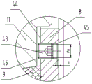
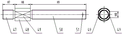
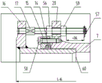
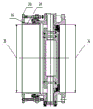
in the figure, 1, a driving device, 2, a flat key, 3, a support, 4, an upper valve shaft, 5, a gland cover, 6, a gland cover, 7, a valve body, 8, a regulating pressure plate, 9, a valve plate sealing ring, 10 pin shafts, 11 valve plates, 12, a lower valve shaft, 13, an end cover, 14, a telescopic gland, 15, a telescopic gland, 16, a telescopic screw, 18, a valve body connecting flange, 19, a flange hole, 20 bulges, 21, a telescopic screw through hole, 22, a telescopic gland fastening hole, 23, a valve body connecting flange sealing surface, 24, 25, 26, a flange hole center circle, 27, a valve shaft center line, 29 bulge planes, 30 standard flanges, 31, 32 limit telescopic screw thread through holes, 33, a double-lug flange end inner channel diameter, 34, an outlet flange end inner channel diameter, 35 shaft shoulders, 36, a shaft shoulder and valve body contact surface, 37, 38 conical stop washers and 39 pressure; a 40 conical cylinder; 41 long ears; 42 short ears; 43 set screws; 44 adjusting the pressure plate to contact the sealing ring side; 45 an internal threaded hole; 46 a valve plate plane; 47 a first threaded portion; 48 cylindrical portions; 49 plane; 50 a second threaded portion; 51 split pin holes; 52 with the mating surface of the extension tube; 53 mating surface with valve body; 54 a raised portion; 55, a bevel; 56 a first nut; 57 a cotter pin; 58 bolts; 59 a second nut; 60 valve body limiting surface.
Detailed Description
The technical solution in the embodiment of the present invention is clearly and completely described below with reference to the accompanying drawings. It is to be understood that the embodiments described are only some embodiments of the invention, and not all embodiments. Based on the embodiments in the present invention, all other embodiments of the ordinary skilled person in the art without creative work belong to the protection scope of the present invention.
The telescopic butterfly valve comprises a valve body 7, a valve shaft, a valve plate 11, a valve plate sealing ring 9, a valve body sealing surface 37 and a support 3.
As shown in fig. 1-2, the valve body connecting flange 18 is designed to have a circle of outwardly extending protrusions distributed on the outer edge of the circumferential surface, each protrusion is located between two flange holes 19, the number of the protrusions 20 is half of the number of the flange holes 19, the protrusions are symmetrically distributed about a center line 28 of the valve shaft, the size of an outer circle 24 of the protrusion is the size of an outer circle of a standard flange, the size of an inner circle 25 of the protrusion is the size of a center circle 26 of the flange hole to reduce the size of the flange hole 19, an included angle α between two protrusion side edges 27 is 40-45 °, the chord length d of two intersection points of the protrusion side edges 27 and the adjacent flange holes 19 on the center circle 26 of the flange hole is 8-12 mm, a telescopic screw rod through hole 21 is drilled on each protrusion 20, the telescopic screw rod through hole 21 is located on the center circle 26 of the flange hole, and is located in the middle position between the two adjacent flange holes.
As shown in fig. 13, the cross-sectional shape of the retractable seal ring 14 is a right trapezoid, two protrusions 54 with a radius of 0.5mm are uniformly distributed on the telescopic pipe fitting surface 52, two protrusions 54 with a radius of 0.5mm are uniformly distributed on the valve body fitting surface 53, two contact surfaces of the retractable gland and the retractable seal ring are provided, one surface slope and the inclined surface fit together to be called a fit inclined surface, one surface parallel and the upper bottom surface fit together to be called a fit plane, an included angle β between the inclined surface 55 and the valve body fitting surface 53 matched with the retractable gland is 30 °, as shown in fig. 17, the inclined surface of the retractable seal ring and the contact point of the retractable gland are located at the bottom of the inclined surface, the contact point is used as a vertex to form a certain included angle between the upper bottom surface direction inclined surface of the right trapezoid and the retractable gland, from a mechanical angle, the lower the point where the inclined surface 55 and the fit inclined surface contact is, the larger the pretightening force provided by the retractable seal ring is provided by the retractable gland, so that the pretightening force provided by the retractable seal ring can be reliably attached to the surface, and the seal ring is reliably designed by the shape of the retractable gland and the.
As shown in fig. 3, the telescopic pipe comprises a standard flange 30 and a pipe body 31 concentrically and fixedly connected to the standard flange, a circle of limit telescopic screw thread through holes 32 are uniformly distributed on the standard flange 30, the number of the limit telescopic screw thread through holes 32 is half of that of the flange holes 19, and the limit telescopic screw thread through holes 32 are arranged on a central circle 26 of the flange holes and are located in the middle of two adjacent flange holes 19. As shown in fig. 4, the pipe body is a standard seamless steel pipe, and the standard flange 30 is welded with the pipe body, so that the diameter 33 of the inner channel at the flange end of the inlet is the nominal diameter of the valve, the diameter 34 of the inner channel at the flange end of the outlet of the valve body 7 is the nominal diameter of the valve when the product is designed, and the inlet and the outlet of the valve are both nominal diameters, namely the full diameter.
As shown in fig. 5, the telescopic butterfly valve adopts an up-down two-stage valve shaft structure. Corresponding shaft shoulders 35 are arranged on the upper valve shaft and the lower valve shaft, the upper valve shaft 4 is provided with an upper shaft shoulder, a contact surface 36 between the shaft shoulder and the valve body is arranged between the upper shaft shoulder and the valve body 7 after assembly, a sealing sleeve 6 and a sealing gland 5 are assembled at the upper end of the upper shaft shoulder, and at the moment, the upper valve shaft 4 is limited in the direction of a center line 28 of the valve shaft. In order to prevent the sealing sleeve 6 from compressing the upper shaft shoulder and increasing the opening and closing torque of the valve, the tolerance requirement of the height dimension H1 of the upper shaft shoulder is (-0.2 to-0.1) mm, the tolerance requirement of the height dimension H2 of the sealing sleeve 6 is (-0.1 to 0) mm, the tolerance requirement of the depth dimension H3 of the boring hole of the valve body 7 is (0 to 0.1) mm, and clearance fit is ensured.
As shown in FIG. 6, the lower valve shaft 12 has a lower shoulder, which has a shoulder-to-valve body contact surface 36 with the valve body 7 after assembly, and the other surface of the lower shoulder is held against the end cap 13, at which time the lower valve shaft 12 is restrained in the direction of the valve shaft centerline 28. In order to prevent the end cover 13 from tightly propping against the lower shaft shoulder and increasing the opening and closing torque of the valve, the tolerance requirement of the height dimension H4 of the lower shaft shoulder 35 of the lower valve shaft 12 is (-0.2 to-0.1) mm, the tolerance requirement of the height dimension H5 of the end cover 13 is (-0.1 to 0) mm, the tolerance requirement of the depth dimension H6 of the boring hole of the valve body 7 is (0 to 0.1) mm, and the clearance fit is ensured.
As shown in fig. 7, the upper valve shaft 4 and the lower valve shaft 12 are connected with the valve plate 11 through the pin shaft 10, when the valve is vertically installed (the valve shaft is vertically upward) on a pipeline, the valve plate 11 is hung on the valve body 7 through the upper valve shaft 4, the valve plate 11 is propped against the end cover 13 through the lower valve shaft 12, two ends of the valve plate 11 are positioned in the direction of the central line 28 of the valve shaft, the uniformity of the interference between the valve plate sealing ring 9 and the sealing surface 37 of the valve body in the circumferential direction is ensured, the valve plate 11 is prevented from falling due to self weight, the interference between the valve plate sealing ring 9 and the sealing surface 37 of the valve body in the.
As shown in fig. 8, the valve plate seal ring 9 is attached to the valve plate 11, the adjusting pressure plate 8 is attached to the valve plate 11 by the pressure plate screw 39, and the tightening torque of the pressure plate screw 39 is adjusted to adjust the interference between the valve plate seal ring 9 and the valve body seal surface 37 in the circumferential direction, thereby keeping the valve sealed. A circle of pressure plate screws 39 are uniformly distributed on the adjusting pressure plate 8, the linear distance between every two adjacent pressure plate screws 39 is 6-8 times of the nominal diameter of the pressure plate screws 39, and each pressure plate screw 39 is provided with a conical double-lug type stop washer 38 to prevent the pressure plate screws 39 from loosening and falling.
As shown in fig. 9, the main body of the conical double-lug type stop washer 38 is a conical cylinder 40, the size of the inner cone of the conical cylinder 40 is consistent with that of the cone of the press plate screw 39 matched with the conical cylinder, and a long lug 41 and a short lug 42 are uniformly distributed in the direction of 180 degrees at the large end of the conical cylinder 40.
As shown in fig. 10, the assembly process of the pressure plate screw and the conical binaural stop washer is as follows: firstly, a pressing plate screw 39 is sleeved into the cone double-lug type stop washer 38, the pressing plate screw 39 penetrates through a pressing plate screw hole on the adjusting pressing plate 8 and is screwed into a corresponding threaded hole on the valve plate 8, and after the pressing plate screw 39 is screwed, the long lug 41 faces towards the excircle direction of the adjusting pressing plate 8, and the short lug 42 faces towards the inner circle direction of the adjusting pressing plate 8. And secondly, knocking the long lug 41 into the hexagonal inner hole of the pressure plate screw 39 to be attached to a plane. In the third step, the short lug 42 is driven into the inner circumference of the adjusting pressure plate 8 to be attached to the inner circumference.
As shown in fig. 11, an internal threaded hole 45 for installing the hexagon socket flat end set screw 43 is drilled in the middle of every two adjacent clamp plate screws 39 on the adjusting clamp plate 8, before the internal threaded hole 45 is drilled, a threaded bottom hole phi a is drilled firstly, then the adjusting clamp plate is contacted with the sealing ring side 44 for tapping, the tapping distance is kept at 1mm, and the length of the hexagon flat end set screw 43 is ensured to be smaller than that of the internal threaded hole 45. The installation step: firstly, screwing the hexagonal flat end set screw 43 into the internal thread hole 45 from the adjusting pressure plate contact seal ring side 44; the adjustment clamp 8 is then installed and the tightening of the clamp screws 39 is described in connection with fig. 8-10. Finally, the hexagonal flat end set screw 43 is rotated to abut the valve plate flat surface 46. The pressure plate screw 39 on the adjusting pressure plate 8 presses the adjusting pressure plate 8 to the valve plate 11, the hexagonal flat end set screw 43 pushes the adjusting pressure plate 8 away from the butterfly plate 11, one pushes one, namely, the position of the adjusting pressure plate 8 is fixed, the interference between the valve plate sealing ring 9 and the valve body sealing surface 37 in the circumferential direction is ensured, the pretightening force is generated again, the pretightening force is prevented for the pressure plate screw 39 and the hexagonal flat end set screw 43, a conical double-lug type stop washer 38 is further mounted on the pressure plate screw 39 for mechanical anti-loosening, and the double anti-loosening effect ensures that the pressure plate screw 39 is not loosened.
The pressure plate screw on the adjusting pressure plate adopts a conical double-lug type stop washer for looseness prevention, and the fastening screw adopts a threaded spigot for looseness prevention.
FIG. 12: the limit telescopic screw 17 mainly consists of three sections: a first threaded portion 47, a cylindrical portion 48; and a second threaded portion 50. The first thread part 47 is screwed into the limit expansion screw thread through hole 32 of the expansion pipe 16, and the length H7 of the first thread part 47 is 3-5 mm shorter than the depth of the limit expansion screw thread through hole 32. 48 length of cylinder portion is 25 ~ 30mm, mills two planes 49 on 48 excircles of cylinder, and plane width H10 is greater than 10mm, and adjustable spanner can rotate it. The second screw part 50 passes through the expansion screw through hole 21 of the boss 20 of the valve body 7, the length H9 of the second screw part 50 is determined according to the expansion distance of the expansion butterfly valve, an opening pin hole 51 is drilled in the second screw part 50, and the position of the opening pin hole 51 is determined according to the expansion distance.
As shown in fig. 14, when the standard installation position of the limit telescopic butterfly valve is determined, the structural length is L, a dimension + △ L is marked between the nut 59 and the cotter 57, it represents that the telescopic tube 16 can be stretched out of the valve body 7 by a distance of △ L, the longest structural length is L + △ L, a dimension- △ L is marked between the telescopic tube 16 and the valve body 7, it represents that the telescopic tube 16 can be pushed into the valve body 7 by a distance of △ L, and the shortest structural length is L- △ L, and the specific installation steps are as follows:
the first thread part 47 of the telescopic screw 17 is completely screwed into the limiting telescopic screw thread through hole 32 on the telescopic pipe 16, the first nut 56 is screwed into the second thread part 50, the telescopic gland 15 and the telescopic sealing ring 14 are sequentially sleeved on the telescopic pipe 16, the telescopic pipe 16 is sleeved into the valve body 7, the second thread part 50 penetrates through the telescopic screw thread through hole 21 on the bulge 20 of the valve body 7, the second nut 59 is screwed into the second thread part 50, the limiting telescopic butterfly valve is adjusted to the standard structure length L, the first nut 56 and the second nut 59 are respectively screwed onto the bulge 20 to fix the structure length L, and the split pin 57 is installed into the split pin hole 51 on the second thread part 50. The telescopic sealing ring 14 is moved to the valve body 7, so that a valve body matching surface 53 of the telescopic sealing ring 14 is in contact with a valve body connecting flange sealing surface 23, the telescopic sealing ring 14 is sleeved in a telescopic gland 15, the telescopic gland 15 is fastened on the valve body 7 through a bolt 58, four surfaces of the telescopic sealing ring 14 are respectively wrapped by the telescopic gland 15, a telescopic pipe 16 and the valve body 7, a tightening torque is applied to the bolt 58, the telescopic gland 15 extrudes the telescopic sealing ring 14, the telescopic sealing ring 14 is a rubber part, after extrusion deformation, a sealing specific pressure is formed between the telescopic sealing ring 14 and the valve body connecting flange sealing surface 23, a sealing specific pressure is formed between the telescopic sealing ring 14 and the telescopic pipe 16, and in addition, four bulges 54 on the telescopic sealing ring 14 enable the sealing.
As shown in fig. 15, in addition to fig. 14, the bolt 58 on the telescopic gland 15 is loosened to make the telescopic sealing ring 14 in a loosened state, the first nut 56 on the telescopic screw 17 is loosened, the telescopic tube 16 is pushed into the valve body 7 with force, so that the telescopic tube 16 is pressed against the valve body limiting surface 60, at this time, the shortest structural length L- △ L of the limiting telescopic butterfly valve is set, the dimension between the second nut 59 and the cotter pin 57 is +2 △ L, the first nut 56 and the second nut 59 are respectively screwed to the protrusion 20, and the bolt 58 on the telescopic gland 15 is screwed, so that the telescopic sealing ring 14 is kept sealed.
As shown in fig. 16, in addition to fig. 14, the bolt 58 on the telescopic gland 15 is loosened to make the telescopic sealing ring 14 in a loose state, the second nut 59 on the telescopic screw 17 is loosened to make the second nut 59 rotate towards the direction of the cotter 57 until the cotter 57 is limited, the telescopic pipe 16 is pulled outwards the valve body 7 with force until the second nut 59 is pressed on the protrusion 20, at this time, the longest structural length L + △ L of the limited telescopic butterfly valve is, the size between the telescopic pipe 16 and the valve body 7 is-2 △ L, the first nut 56 is screwed on the protrusion 20, the second nut 59 is also pressed on the protrusion 20 while the first nut 56 is screwed, and the bolt 58 on the telescopic gland 15 is screwed to keep the telescopic sealing ring 14 sealed.
The extension tube has limit in the external stretching and the internal pushing of the valve body, and the over-stretching and the over-pushing are prevented.
The telescopic pipe stretches outwards the valve body, the structural length of the telescopic butterfly valve can be increased, the telescopic pipe pushes and presses inwards the valve body, and the structural length of the telescopic butterfly valve can be reduced, so that the structural length of the telescopic butterfly valve is identical to the reserved length between two flanges in a construction site, and the installation of the telescopic butterfly valve is guaranteed.
The driving device 1 drives the upper valve shaft to rotate clockwise through the flat key 2, the upper valve shaft drives the valve plate 11 to rotate clockwise through the pin shaft 10, and the valve is closed; the driving device drives the upper valve shaft to rotate anticlockwise through the flat key, the upper valve shaft drives the valve plate to rotate anticlockwise through the pin shaft, and the valve is opened.
Claims (9)
1. Flexible butterfly valve, it includes valve body, valve shaft, valve plate sealing washer, the sealed face of valve body and extensible member, characterized by: the valve plate sealing washer passes through adjusting plate to be fixed on the valve plate, adjusting plate passes through a plurality of clamp plate fix with screws on the butterfly plate, the clamp plate screw centers on the horizontal interval distribution of valve plate, be equipped with circular cone double-ear formula lock washer between adjusting plate and the clamp plate screw, circular cone double-ear formula lock washer includes the circular cone barrel with the nut external diameter looks adaptation of clamp plate screw, the big face of circular cone barrel has long ear and short ear, the laminating of long ear is on the nut of clamp plate screw, the laminating of short ear is on adjusting plate's outer edge.
2. The telescoping butterfly valve of claim 1, wherein: the linear distance between two adjacent pressure plate screws is 6-8 times of the nominal diameter of the pressure plate screw.
3. The telescoping butterfly valve of claim 1, wherein: an inner threaded hole is formed in the adjusting pressure plate between every two adjacent pressure plate screws, and a set screw in contact with the butterfly plate is in threaded fit in the inner threaded hole.
4. The telescoping butterfly valve of claim 1, wherein: the telescopic part comprises a telescopic pipe, a telescopic gland, a telescopic screw and a valve body connecting flange, the telescopic pipe comprises a standard flange and a pipe body concentrically and fixedly connected on the standard flange, a circle of telescopic screw through holes and a circle of flange holes which are distributed in a staggered manner are uniformly distributed on the circumferential surface of the standard flange, a circle of bulges which extend outwards are distributed on the outer edge of the circumferential surface of the valve body connecting flange, the bulges are provided with telescopic screw through holes and are positioned between two adjacent flange holes, the inner edge of the circumferential surface of the valve body connecting flange is provided with a valve body connecting flange sealing surface, a circle of telescopic gland fastening holes are also distributed on the middle part of the circumferential surface of the valve body connecting flange, the telescopic screw comprises a first screw thread part which is in threaded fit with the telescopic screw through holes of the telescopic pipe, a cylindrical part and a second screw, the telescopic gland is in threaded connection with the telescopic gland fastening hole of the valve body connecting flange through a bolt.
5. The telescoping butterfly valve of claim 4, wherein: and the tail ends of the two threaded parts are provided with split pins.
6. The telescoping butterfly valve of claim 4, wherein: the telescopic sealing ring is characterized in that telescopic sealing rings are arranged among the telescopic gland, the pipe body and the valve body connecting flange, and protruding parts are respectively arranged on the contact surfaces of the telescopic sealing rings and the pipe body and the contact surfaces of the telescopic sealing rings and the valve body connecting flange, so that the telescopic sealing rings, the pipe body and the valve body connecting flange are in interference fit.
7. The telescoping butterfly valve of claim 6, wherein: the section of the telescopic sealing ring is in a right trapezoid shape, the inclined surface and the upper bottom surface of the telescopic sealing ring are in contact with the telescopic gland, the lower bottom surface of the telescopic sealing ring is in contact with the pipe body, the right-angle surface of the telescopic sealing ring is in contact with the valve body connecting flange, the contact point of the inclined surface and the telescopic gland is located at the bottom of the inclined surface, and an included angle of 2-5 degrees is formed between the inclined surface and the telescopic gland in the direction of the upper bottom surface of the.
8. The telescoping butterfly valve of claim 1, wherein: the valve shaft comprises an upper valve shaft and a lower valve shaft, an upper shaft shoulder is arranged on the upper valve shaft, a sealing sleeve and a sealing gland are arranged on the upper shaft shoulder, the sealing sleeve and the upper shaft shoulder are in clearance fit in the vertical direction, a lower shaft shoulder is arranged on the lower valve shaft, the bottom of the lower shaft shoulder is in contact with an end cover fixed at the bottom of the valve body, and the lower shaft shoulder is in clearance fit with the valve body in the vertical direction.
9. The telescoping butterfly valve of claim 8, wherein: the upper valve shaft and the lower valve shaft are respectively connected with the valve plate through pin shafts.
Priority Applications (1)
| Application Number | Priority Date | Filing Date | Title |
|---|---|---|---|
| CN201921054251.2U CN210372054U (en) | 2019-07-08 | 2019-07-08 | Telescopic butterfly valve |
Applications Claiming Priority (1)
| Application Number | Priority Date | Filing Date | Title |
|---|---|---|---|
| CN201921054251.2U CN210372054U (en) | 2019-07-08 | 2019-07-08 | Telescopic butterfly valve |
Publications (1)
| Publication Number | Publication Date |
|---|---|
| CN210372054U true CN210372054U (en) | 2020-04-21 |
Family
ID=70270318
Family Applications (1)
| Application Number | Title | Priority Date | Filing Date |
|---|---|---|---|
| CN201921054251.2U Expired - Fee Related CN210372054U (en) | 2019-07-08 | 2019-07-08 | Telescopic butterfly valve |
Country Status (1)
| Country | Link |
|---|---|
| CN (1) | CN210372054U (en) |
Cited By (1)
| Publication number | Priority date | Publication date | Assignee | Title |
|---|---|---|---|---|
| CN110388472A (en) * | 2019-07-08 | 2019-10-29 | 英诺威阀业有限公司 | Flexible butterfly valve |
-
2019
- 2019-07-08 CN CN201921054251.2U patent/CN210372054U/en not_active Expired - Fee Related
Cited By (1)
| Publication number | Priority date | Publication date | Assignee | Title |
|---|---|---|---|---|
| CN110388472A (en) * | 2019-07-08 | 2019-10-29 | 英诺威阀业有限公司 | Flexible butterfly valve |
Similar Documents
| Publication | Publication Date | Title |
|---|---|---|
| CN210372054U (en) | Telescopic butterfly valve | |
| CN109519541B (en) | Built-in high-pressure manhole device and opening and closing operation method thereof | |
| CN210106370U (en) | Fastening system, to-be-assembled part and self-locking nut with reverse teeth | |
| CN205989171U (en) | A kind of stud erecting device | |
| CN113404954B (en) | Underwater bolt pre-tightening telescopic connector | |
| CN205226357U (en) | Manhole mechanism on high -tension apparatus barrel | |
| CN210830897U (en) | Outer flange plate capable of being installed quickly | |
| CN105276186B (en) | Manhole mechanism on high-tension apparatus cylinder | |
| CN210068710U (en) | Sleeve locking loose-proof nut | |
| CN209309102U (en) | A kind of photovoltaic bolt | |
| CN112628520A (en) | High-pressure self-tightening pipeline plugging device | |
| CN215522446U (en) | Efficient sealing blind flange | |
| CN205226366U (en) | Manhole mechanism on high -tension apparatus barrel | |
| KR100511518B1 (en) | Prevent secession pressed wheel for cast iron pipe | |
| CN110388472A (en) | Flexible butterfly valve | |
| CN201748014U (en) | Gate valve with check double loose joints | |
| CN209943312U (en) | Round sealing nut | |
| CN105299225A (en) | Manhole mechanism on high-pressure equipment barrel | |
| KR200294925Y1 (en) | Prevent secession pressed wheel for cast iron pipe | |
| CN220249239U (en) | Tensile sealing gas drainage pipe butt joint device | |
| CN221921968U (en) | Deep sea environment test storehouse seal structure | |
| CN202834549U (en) | Rigid pipe joint with extensible offset function | |
| CN215108042U (en) | Handle lock | |
| CN220980594U (en) | Pipeline watertight seal structure | |
| CN210424115U (en) | Novel diesel engine cylinder cover engine oil connecting assembly |
Legal Events
| Date | Code | Title | Description |
|---|---|---|---|
| GR01 | Patent grant | ||
| GR01 | Patent grant | ||
| CF01 | Termination of patent right due to non-payment of annual fee | ||
| CF01 | Termination of patent right due to non-payment of annual fee |
Granted publication date: 20200421 |