CN210366364U - Cabling machine wire winding turntable structure - Google Patents
Cabling machine wire winding turntable structure Download PDFInfo
- Publication number
- CN210366364U CN210366364U CN201921012334.5U CN201921012334U CN210366364U CN 210366364 U CN210366364 U CN 210366364U CN 201921012334 U CN201921012334 U CN 201921012334U CN 210366364 U CN210366364 U CN 210366364U
- Authority
- CN
- China
- Prior art keywords
- supporting plate
- support plate
- rotating shaft
- plate
- base
- Prior art date
- Legal status (The legal status is an assumption and is not a legal conclusion. Google has not performed a legal analysis and makes no representation as to the accuracy of the status listed.)
- Expired - Fee Related
Links
Images


Landscapes
- Storage Of Web-Like Or Filamentary Materials (AREA)
Abstract
The utility model discloses a cable-former wire winding carousel structure belongs to cable rolling technical field. A winding turntable structure of a cabling machine comprises a base, wherein a first supporting plate group and a second supporting plate group are connected to the base, the first supporting plate group mainly comprises a first fixed supporting plate and a movable supporting plate, the first fixed supporting plate is fixedly connected with the base, and the movable supporting plate is connected with the base in a sliding manner; the movable support plate is rotatably connected with a rotating shaft, one end of the rotating shaft, far away from the movable support plate, is rotatably connected with the first fixed support plate, the wire spool is clamped on the rotating shaft, and the movable support plate is connected with a first driving part corresponding to the rotating shaft; the second support plate group mainly comprises two second fixed support plates, the second fixed support plates are rotatably connected with screws, the screws are in threaded connection with a movable plate, the movable plate is provided with wire holes, and the second fixed support plates are connected with second driving parts corresponding to the screws; the utility model discloses be convenient for dismantle and install the wire winding dish, receive the line moreover and evenly be difficult to produce and receive the line gap, improved processingquality.
Description
Technical Field
The utility model relates to a cable rolling technical field especially relates to a cable-former wire winding carousel structure.
Background
The cable is in the processing back that finishes, can be rolled up on the reel usually, with the cable rolling on the reel, the storage and the transportation of the cable of being convenient for, along with the development of science and technology, degree of automation's deepening, at the in-process with the cable rolling to the cable dish, the machine has replaced the manual work gradually and has come rotatory cable dish to roll up the cable.
In the prior art, as patent numbers: CN201820633559.1, announcement date is: 2018-12-11 discloses a communication cable coiling device, which comprises a bottom plate, a right side fixedly connected with first vertical plate at the top of the bottom plate, a right side fixedly connected with supporting plate of the first vertical plate, a top fixedly connected with motor of the supporting plate, an output end of the motor penetrates through a left side fixedly connected with coiling disc of the first vertical plate, and a left side fixedly connected with second vertical plate at the top of the bottom plate and positioned on the first vertical plate. The working principle is as follows: through setting up the bottom plate, the riser, the backup pad, including a motor, an end cap, a controller, and a cover plate, the rolling dish, the second riser, the apparatus further comprises a rotating shaft, the locking gear, the box, the fixed block, the rotor plate, the transfer line, the locating piece, the cylinder, the polished rod, the sliding ring, the transmission frame, the cooperation of connecting rod and locking pinion rack is used, the problem that current cable coiling mechanism does not have the locking function has been solved, this communication cable coiling mechanism possesses and prevents rolling dish pivoted advantage, the rolling dish is difficult to rotate, convenient to use person uses, cable coiling mechanism's practicality has been improved.
Above-mentioned scheme, though possess the advantage that prevents the rolling dish and rotate, nevertheless have following not enough: 1. The winding disc is inconvenient to mount and dismount because the winding disc is heavy after being coiled; 2. the cable cannot be uniformly wound during winding, so that gaps exist among all layers of cables to influence the quality of finished products, and therefore a winding turntable structure of the cable former is provided to solve the problems.
SUMMERY OF THE UTILITY MODEL
The utility model aims at solving the defects in the prior art and providing a cable-former wire winding turntable structure.
In order to achieve the above purpose, the utility model adopts the following technical scheme:
a winding turntable structure of a cabling machine comprises a base, wherein a first supporting plate group and a second supporting plate group are connected to the base, the first supporting plate group mainly comprises a first fixed supporting plate and a movable supporting plate, the first fixed supporting plate is fixedly connected with the base, and the movable supporting plate is connected with the base in a sliding manner;
the wire spool is clamped on the rotating shaft, and the movable support plate is connected with a first driving part corresponding to the rotating shaft;
the second support plate group mainly comprises two second fixed support plates, the second fixed support plates are rotatably connected with screw rods, the screw rods are in threaded connection with movable plates, the movable plates are provided with wire holes, and the second fixed support plates are connected with second driving parts corresponding to the screw rods.
Preferably, the rotating shaft is fixedly connected with a key block, and the wire spool is provided with a key slot corresponding to the key block.
Preferably, the first driving part comprises a first motor, a baffle is fixedly connected to the movable support plate, the first motor is mounted on the baffle, the rotating shaft is rotatably connected with the baffle, the output end of the first motor is connected with a first belt wheel, a second belt wheel is fixedly connected to the rotating shaft, and the first belt wheel is rotatably connected with the second belt wheel through a belt.
Preferably, the second driving part comprises a second motor, the second motor is mounted on the second fixed support plate, and an output end of the second motor is connected with the screw rod.
Preferably, a sliding rod is fixedly connected to the second fixed support plate, and the moving plate is connected with the sliding rod in a sliding mode.
Preferably, a sliding groove is formed in the base, a sliding block is arranged at the bottom of the movable support plate, and the sliding block is connected with the sliding groove in a sliding mode.
Preferably, the base is provided with a slot, the movable support plate is provided with a through slot, and the through slot is internally and slidably connected with an insert block corresponding to the slot.
Compared with the prior art, the utility model provides a cable-former wire winding carousel structure possesses following beneficial effect:
1. the cable-former wire-winding turntable structure drives a first belt wheel to rotate by starting a first motor, further drives a second belt wheel to rotate by a belt, further drives a rotating shaft to rotate, simultaneously starts a second motor to drive a screw rod to rotate, further causes a moving plate on the screw rod to move, further controls the second motor to rotate forwards and backwards by additionally arranging a controller on the second motor, further causes the moving plate to move leftwards and rightwards, further causes a cable to move leftwards and rightwards through a wire hole and to be wound on a wire winding disc, thereby avoiding the cable from being wound at the same place to generate a gap, after wire winding is finished, the cable-former wire-winding turntable structure is connected into a jack hole on the wire winding disc by an existing crane or an electric hoist, then causes a moving support plate to move through a chute, further causes the moving support plate to drive the rotating shaft to move out of the wire winding disc, further remo, the utility model discloses be convenient for dismantle and install the wire winding dish, receive the line moreover and evenly be difficult to produce and receive the line gap, improved processingquality.
Drawings
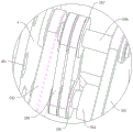
Fig. 1 is a first structural schematic view of a winding turntable structure of a cabling machine according to the present invention;
fig. 2 is a structural schematic view of a wire winding turntable structure of the cabling machine according to the present invention;
fig. 3 is a third schematic structural view of a winding turntable structure of a cabling machine according to the present invention;
fig. 4 is a fourth schematic structural view of a winding turntable structure of a cabling machine according to the present invention;
fig. 5 is a schematic structural view of a winding turntable structure of a cabling machine according to the present invention;
fig. 6 is a schematic structural diagram of a portion a in the structure diagram 2 of the winding turntable of the cabling machine of the present invention.
In the figure: 1. a base; 101. a chute; 102. a slot; 2. a first brace bar group; 201. a first fixed support plate; 202. moving the support plate; 2021. a through groove; 2022. inserting a block; 203. a baffle plate; 204. a first motor; 205. a first pulley; 206. a rotating shaft; 2061. a key block; 207. a second pulley; 208. a belt; 3. a second group of buttresses; 301. a screw; 302. a second motor; 303. A slide bar; 304. moving the plate; 305. a wire hole; 4. a wire spool; 401. a lifting hole; 402. A keyway.
Detailed Description
The technical solutions in the embodiments of the present invention will be described clearly and completely with reference to the accompanying drawings in the embodiments of the present invention, and it is obvious that the described embodiments are only some embodiments of the present invention, not all embodiments.
In the description of the present invention, it is to be understood that the terms "upper", "lower", "front", "rear", "left", "right", "top", "bottom", "inner", "outer", and the like indicate orientations or positional relationships based on the orientations or positional relationships shown in the drawings, and are only for convenience of description and simplicity of description, and do not indicate or imply that the device or element being referred to must have a particular orientation, be constructed and operated in a particular orientation, and therefore, should not be construed as limiting the present invention.
Referring to fig. 1-6, a winding turntable structure of a cabling machine comprises a base 1, wherein a first supporting plate group 2 and a second supporting plate group 3 are connected to the base 1, the first supporting plate group 2 mainly comprises a first fixed supporting plate 201 and a movable supporting plate 202, the first fixed supporting plate 201 is fixedly connected with the base 1, and the movable supporting plate 202 is slidably connected with the base 1;
a rotating shaft 206 is rotatably connected to the movable support plate 202, one end of the rotating shaft 206, which is far away from the movable support plate 202, is rotatably connected to the first fixed support plate 201, the wire spool 4 is clamped to the rotating shaft 206, and the movable support plate 202 is connected to a first driving part corresponding to the rotating shaft 206;
the second supporting plate group 3 mainly comprises two second fixed supporting plates, a screw 301 is rotatably connected to each second fixed supporting plate, a moving plate 304 is connected to each screw 301 in a threaded manner, a wire hole 305 is formed in each moving plate 304, and a second driving portion corresponding to each screw 301 is connected to each second fixed supporting plate.
A key block 2061 is fixedly connected to the rotating shaft 206, and a key groove 402 corresponding to the key block 2061 is provided on the spool 4.
The first driving portion comprises a first motor 204, a baffle 203 is fixedly connected to the movable support plate 202, the first motor 204 is installed on the baffle 203, a rotating shaft 206 is rotatably connected with the baffle 203, the output end of the first motor 204 is connected with a first belt pulley 205, a second belt pulley 207 is fixedly connected to the rotating shaft 206, and the first belt pulley 205 and the second belt pulley 207 are rotatably connected through a belt 208.
The second driving part comprises a second motor 302, the second motor 302 is mounted on the second fixed support plate, and the output end of the second motor 302 is connected with the screw 301.
A sliding rod 303 is fixedly connected to the second fixed support plate, and the moving plate 304 is slidably connected with the sliding rod 303.
The base 1 is provided with a sliding groove 101, the bottom of the movable support plate 202 is provided with a sliding block, and the sliding block is connected with the sliding groove 101 in a sliding manner.
The base 1 is provided with a slot 102, the movable support plate 202 is provided with a through groove 2021, and the through groove 2021 is slidably connected with an insertion block 2022 corresponding to the slot 102.
In the utility model, when the user uses the cable winding machine, the first motor 204 is started to drive the first pulley 205 to rotate, the belt 208 is further used to drive the second pulley 207 to rotate, the rotating shaft 206 is further rotated, the second motor 302 is simultaneously started to drive the screw 301 to rotate, the moving plate 304 on the screw 301 is further moved, the second motor 302 is further controlled to rotate forward and backward by adding a controller on the second motor 302, the moving plate 304 is moved leftwards and rightwards, the cable is moved leftwards and rightwards through the wire hole 305 and is wound on the wire spool 4, thereby preventing the cable from being wound on the same place to generate gaps, after the cable winding is completed, the cable winding machine is connected to the hoisting hole 401 on the wire spool 4 through the existing crane or electric hoist, then the inserting block 2022 is pulled, thereby the moving support plate 202 is moved through the chute 101, and the moving support plate 202 drives the rotating shaft 206 to move out, and then reinstallate wire reel 4 to fix keyway 402 in wire reel 4 through key piece 2061, the utility model discloses be convenient for dismantle and install wire reel 4, receive the line moreover and evenly be difficult to produce and receive the line gap, improved processingquality.
The above, only be the concrete implementation of the preferred embodiment of the present invention, but the protection scope of the present invention is not limited thereto, and any person skilled in the art is in the technical scope of the present invention, according to the technical solution of the present invention and the utility model, the concept of which is equivalent to replace or change, should be covered within the protection scope of the present invention.
Claims (7)
1. A winding turntable structure of a cabling machine comprises a base (1), and is characterized in that a first supporting plate group (2) and a second supporting plate group (3) are connected to the base (1), the first supporting plate group (2) mainly comprises a first fixed supporting plate (201) and a movable supporting plate (202), the first fixed supporting plate (201) is fixedly connected with the base (1), and the movable supporting plate (202) is connected with the base (1) in a sliding manner;
the movable support plate (202) is rotatably connected with a rotating shaft (206), one end, far away from the movable support plate (202), of the rotating shaft (206) is rotatably connected with the first fixed support plate (201), the rotating shaft (206) is clamped with a wire spool (4), and the movable support plate (202) is connected with a first driving part corresponding to the rotating shaft (206);
the second supporting plate group (3) mainly comprises two second fixed supporting plates, a screw rod (301) is rotatably connected onto the second fixed supporting plates, a moving plate (304) is connected onto the screw rod (301) in a threaded mode, a wire hole (305) is formed in the moving plate (304), and a second driving portion corresponding to the screw rod (301) is connected onto the second fixed supporting plates.
2. The cabling machine wire winding turntable structure according to claim 1, wherein a key block (2061) is fixedly connected to the rotating shaft (206), and a key slot (402) corresponding to the key block (2061) is formed on the wire winding disc (4).
3. The cabling machine wire winding turntable structure according to claim 2, wherein the first driving portion comprises a first motor (204), a baffle (203) is fixedly connected to the movable support plate (202), the first motor (204) is mounted on the baffle (203), the rotating shaft (206) is rotatably connected to the baffle (203), a first pulley (205) is connected to an output end of the first motor (204), a second pulley (207) is fixedly connected to the rotating shaft (206), and the first pulley (205) is rotatably connected to the second pulley (207) through a belt (208).
4. A cabling machine reel turntable structure according to any one of claims 1-3, wherein the second driving part comprises a second motor (302), the second motor (302) is mounted on a second fixed support plate, and the output end of the second motor (302) is connected to the screw (301).
5. The cabling machine winding turntable structure according to claim 4, wherein a sliding rod (303) is fixedly connected to the second fixed support plate, and the moving plate (304) is slidably connected to the sliding rod (303).
6. A cabling machine reel turntable structure according to any one of claims 1-3, wherein the base (1) is provided with a sliding groove (101), and the bottom of the movable support plate (202) is provided with a slide block, and the slide block is slidably connected with the sliding groove (101).
7. The cabling machine winding turntable structure according to claim 6, wherein the base (1) is provided with a slot (102), the movable support plate (202) is provided with a through slot (2021), and the through slot (2021) is slidably connected with an insert block (2022) corresponding to the slot (102).
Priority Applications (1)
| Application Number | Priority Date | Filing Date | Title |
|---|---|---|---|
| CN201921012334.5U CN210366364U (en) | 2019-07-02 | 2019-07-02 | Cabling machine wire winding turntable structure |
Applications Claiming Priority (1)
| Application Number | Priority Date | Filing Date | Title |
|---|---|---|---|
| CN201921012334.5U CN210366364U (en) | 2019-07-02 | 2019-07-02 | Cabling machine wire winding turntable structure |
Publications (1)
| Publication Number | Publication Date |
|---|---|
| CN210366364U true CN210366364U (en) | 2020-04-21 |
Family
ID=70268516
Family Applications (1)
| Application Number | Title | Priority Date | Filing Date |
|---|---|---|---|
| CN201921012334.5U Expired - Fee Related CN210366364U (en) | 2019-07-02 | 2019-07-02 | Cabling machine wire winding turntable structure |
Country Status (1)
| Country | Link |
|---|---|
| CN (1) | CN210366364U (en) |
Cited By (7)
| Publication number | Priority date | Publication date | Assignee | Title |
|---|---|---|---|---|
| CN111762626A (en) * | 2020-07-22 | 2020-10-13 | 珠海格力电工有限公司 | Device capable of winding wire on wire coil |
| CN112234514A (en) * | 2020-10-26 | 2021-01-15 | 韩悦 | Improved wire tightener for high-voltage stringing |
| CN112478921A (en) * | 2020-12-15 | 2021-03-12 | 郑金芳 | Cable carrying and coiling device |
| CN112850352A (en) * | 2020-12-29 | 2021-05-28 | 广东省电信规划设计院有限公司 | Cable coiling mechanism is used in communication technology development |
| CN113053563A (en) * | 2021-03-29 | 2021-06-29 | 刘长庆 | Automatic winding device for steel-cored aluminum strand and operation method thereof |
| CN113942894A (en) * | 2021-11-29 | 2022-01-18 | 国网河南省电力公司卢氏县供电公司 | Automatic winding device for electric power construction |
| CN115258818A (en) * | 2022-06-27 | 2022-11-01 | 国网山东省电力公司汶上县供电公司 | Cable anti-winding auxiliary device |
-
2019
- 2019-07-02 CN CN201921012334.5U patent/CN210366364U/en not_active Expired - Fee Related
Cited By (7)
| Publication number | Priority date | Publication date | Assignee | Title |
|---|---|---|---|---|
| CN111762626A (en) * | 2020-07-22 | 2020-10-13 | 珠海格力电工有限公司 | Device capable of winding wire on wire coil |
| CN112234514A (en) * | 2020-10-26 | 2021-01-15 | 韩悦 | Improved wire tightener for high-voltage stringing |
| CN112478921A (en) * | 2020-12-15 | 2021-03-12 | 郑金芳 | Cable carrying and coiling device |
| CN112850352A (en) * | 2020-12-29 | 2021-05-28 | 广东省电信规划设计院有限公司 | Cable coiling mechanism is used in communication technology development |
| CN113053563A (en) * | 2021-03-29 | 2021-06-29 | 刘长庆 | Automatic winding device for steel-cored aluminum strand and operation method thereof |
| CN113942894A (en) * | 2021-11-29 | 2022-01-18 | 国网河南省电力公司卢氏县供电公司 | Automatic winding device for electric power construction |
| CN115258818A (en) * | 2022-06-27 | 2022-11-01 | 国网山东省电力公司汶上县供电公司 | Cable anti-winding auxiliary device |
Similar Documents
| Publication | Publication Date | Title |
|---|---|---|
| CN210366364U (en) | Cabling machine wire winding turntable structure | |
| CN112408088A (en) | Wire and cable winding equipment | |
| CN214087082U (en) | Pay-off is used in electric power construction | |
| CN208802688U (en) | A kind of coil winding machine | |
| CN217788095U (en) | Centralized hanging wall device of frame winch | |
| CN217051114U (en) | Cable processing take-up device convenient to quick assembly disassembly | |
| CN115985585A (en) | Automatic storage dish device for trading dish of frame winch | |
| CN215797659U (en) | Cable winding device convenient for fixing cable head for electric power engineering | |
| CN110589614B (en) | Wire coil transfer device | |
| CN211225645U (en) | Automatic winding equipment for producing non-woven fabric | |
| CN112478936A (en) | Cable take-up device for electric power engineering construction | |
| CN210305054U (en) | Special upset platform of oriented silicon steel | |
| CN217157830U (en) | Cable mica tape wrapping machine | |
| CN220502248U (en) | Automatic processing equipment for mobile phone data line | |
| CN213400863U (en) | Winding device of T1 coil | |
| CN215625870U (en) | Insulated wire coiling device | |
| CN217398074U (en) | Take-up device convenient to change dish | |
| CN218289771U (en) | A upward roll device for sheet metal production | |
| CN220181169U (en) | Be used for full-automatic work piece film coiler | |
| CN220078130U (en) | Cable pay-off rack with auxiliary driving structure | |
| CN213923509U (en) | Cable take-up device capable of preventing diagonal pulling | |
| CN213265087U (en) | Wire rod take-up device | |
| CN219031320U (en) | Auxiliary fixture for winding | |
| CN220509766U (en) | Winding device for cable preparation | |
| CN215111786U (en) | Security protection information platform convenient to detect maintenance equipment |
Legal Events
| Date | Code | Title | Description |
|---|---|---|---|
| GR01 | Patent grant | ||
| GR01 | Patent grant | ||
| CF01 | Termination of patent right due to non-payment of annual fee | ||
| CF01 | Termination of patent right due to non-payment of annual fee |
Granted publication date: 20200421 Termination date: 20210702 |