CN210337912U - Electrified construction ladder car of adjustable level railway - Google Patents
Electrified construction ladder car of adjustable level railway Download PDFInfo
- Publication number
- CN210337912U CN210337912U CN201921382109.0U CN201921382109U CN210337912U CN 210337912 U CN210337912 U CN 210337912U CN 201921382109 U CN201921382109 U CN 201921382109U CN 210337912 U CN210337912 U CN 210337912U
- Authority
- CN
- China
- Prior art keywords
- ladder
- platform
- wire rope
- steel wire
- ladder car
- Prior art date
- Legal status (The legal status is an assumption and is not a legal conclusion. Google has not performed a legal analysis and makes no representation as to the accuracy of the status listed.)
- Active
Links
Images
Landscapes
- Ladders (AREA)
Abstract
The utility model belongs to the railway construction field, a leveling railway electrification construction ladder car is proposed, including base platform, counter weight body, stand support, ladder car top support and work platform, the counter weight body sets up on the platform of bottom, the base platform bottom is provided with the walking wheel, four stand supports fixed mounting are in the four corners of base platform, the top support is installed at the stand support top and is connected each stand support; two pulleys and a steel wire rope are respectively arranged on two sides of the working platform, one end of the steel wire rope is fixed on the top support of the ladder car, the other end of the steel wire rope penetrates through the two pulleys on the same side and then is fixedly connected with the top support of the ladder car, and a steel wire rope hand block is arranged on one steel wire rope. The utility model discloses can realize work platform's leveling, improve the construction security.
Description
Technical Field
The utility model belongs to railway construction field, concretely relates to electrified construction ladder car of leveling railway.
Background
Electrified railway construction will use the tower wagon to adjust the contact net wire, place the tower wagon and carry out on the railway line, and constructor stands and carries out the operation in tower wagon upper portion work platform rail, makes the contact net reach relevant technical requirement. At present, most of ladder cars for electrified railway construction in China are welded by steel pipes and are very heavy, and the upper working platform fence of the ladder car is welded and fixed and cannot move; meanwhile, the height of the line of the contact network of the electrified railway is generally more than 6.1 meters, the height of a commonly used ladder car is also about 5.5 meters, and the ladder car is high, heavy and inconvenient to transport. How to conveniently and rapidly assemble the ladder car and enable the working platform fence on the ladder car to automatically adjust the level along with the inclination degree of the railway line is a technical problem to be solved by technical personnel in the field.
SUMMERY OF THE UTILITY MODEL
The utility model overcomes the deficiencies in the prior art, the technical problem who solves is: the ladder car is convenient to use and capable of adjusting the level of railway electrification construction.
In order to solve the technical problem, the utility model discloses a technical scheme be: a leveling-adjustable railway electrification construction ladder vehicle comprises a base platform, a counterweight body, upright post supports, a ladder vehicle top support and a working platform, wherein the counterweight body is arranged on the bottom platform; two pulleys and a steel wire rope are respectively arranged on two sides of the working platform, one end of the steel wire rope is fixed on the top support of the ladder car, the other end of the steel wire rope penetrates through the two pulleys on the same side and then is fixedly connected with the top support of the ladder car, and a steel wire rope hand-operated block is arranged on one steel wire rope.
The leveling-adjustable railway electrification construction ladder car further comprises a plurality of connecting inclined strut supports, and the connecting inclined strut supports are arranged between two adjacent upright post supports.
And platform fences are arranged around the working platform.
The leveling-adjustable electrified railway construction ladder car further comprises a connecting loop bar, wherein two ends of the connecting loop bar are respectively provided with a lantern ring, one end of the connecting loop bar is connected with four corners of the working platform through the lantern ring, and the other end of the connecting loop bar is connected with the upright post bracket through the lantern ring.
The leveling-adjustable railway electrification construction ladder car further comprises a rope ladder hung on a support at the top of the ladder car.
Compared with the prior art, the utility model following beneficial effect has: the utility model provides an assembled leveling railway electrification construction ladder car, its work platform can the level of adjustment, can be applied to in the electrified construction of railway bend, and this ladder car simple structure is stable, can effectively guarantee constructor safety.
Drawings
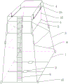
FIG. 1 is a schematic structural view of an electrified construction ladder vehicle for a leveling-adjustable railway provided by the present invention;
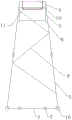
FIG. 2 is a side view of FIG. 1;
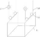
fig. 3 is a schematic view of the installation of the work platform.
In the figure: the platform comprises a base platform 1, a counterweight body 2, a column support 3, a ladder car top support 4, a working platform 5, a connecting loop bar 6, a steel wire rope hand-operated block 7, a diagonal support 8, a rope ladder 9, a steel wire rope 10, a pulley 11 and a platform fence 12.
Detailed Description
In order to make the objects, technical solutions and advantages of the embodiments of the present invention clearer, the technical solutions of the embodiments of the present invention will be clearly and completely described below, and it is obvious that the described embodiments are some, but not all, embodiments of the present invention; based on the embodiments in the present invention, all other embodiments obtained by a person skilled in the art without creative efforts belong to the protection scope of the present invention.
As shown in fig. 1 to 3, an embodiment of the present invention provides a leveling-adjustable railway electrification construction ladder vehicle, which includes a base platform 1, a counterweight body 2, upright supports 3, a ladder vehicle top support 4 and a working platform 5, wherein the counterweight body 2 is arranged on the bottom platform 1, walking wheels 10 are arranged at the bottom of the base platform 1, four upright supports 3 are fixedly installed at four corners of the base platform 1, and the ladder vehicle top support 4 is installed at the top of the upright support 3 and is connected with each upright support 3; two pulleys 11 and a steel wire rope 10 are respectively arranged on two sides of the working platform 5, one end of the steel wire rope 10 is fixed on the top support 4 of the ladder car, the other end of the steel wire rope 10 penetrates through the two pulleys 11 on the same side and then is fixedly connected with the top support 4 of the ladder car, and a steel wire rope hand-operated hoist 7 is arranged on one steel wire rope 10. Wherein, through the cooperation of wire rope and two pulleys, can automatic adjustment work platform's front and back level, through adjusting wire rope hand block, can adjust the levelness of work platform left and right sides. In addition, the number of the steel wire rope hand-operated blocks can be 2, and one steel wire rope is arranged on each steel wire rope, so that the overall height of the working platform can be adjusted.
In addition, in this embodiment, construction ladder car still includes many connection bracing support 8, it sets up between two adjacent stand supports 3 to connect the bracing support for increase ladder car structural stability.
Specifically, in this embodiment, platform rail 12 is arranged around the work platform, and the platform rail can protect the construction safety of the worker. The pulley 11 can be fixed on the working platform, and also can be fixedly arranged on the platform fence 12.
Specifically, in this embodiment, still set up the sliding tray who is used for moving the counter weight body on the base platform 1 of construction ladder car, the counter weight body sets up on sliding tray, when the position of the counter weight body needs to be adjusted, moves the counter weight body through promoting sliding tray, then it can to lock sliding tray.
Specifically, in this embodiment, the construction ladder vehicle further includes four connecting sleeve rods 6, the two ends of the connecting sleeve rods 6 are provided with lantern rings, one end of each connecting sleeve rod is connected with the working platform 5 or four corners of the platform fence 12 on the working platform 5 through the lantern rings respectively, and the other end of each connecting sleeve rod is connected with the upright support 3 through the lantern rings. The lantern ring of one end is directly sleeved on the upright post bracket 3, and the lantern ring of the other end is directly sleeved on the connecting rods or the connecting rings at the four corners of the working platform. The working platform is limited through the connecting rods, and the working platform can be prevented from shaking. Furthermore, the connecting sleeve rod can be a telescopic rod, and the telescopic function can be realized through a screw rod and a screw thread rod which are matched with each other.
Specifically, in this embodiment, the construction ladder vehicle further includes a rope ladder 9 provided on a top bracket suspended from the ladder vehicle.
The main structure of construction ladder car that this embodiment provided can be for the steel pipe equipment formation, and its installation as follows: the first step is to assemble the base of the ladder car, use four hard aluminum alloy square tubes to connect and assemble into a square shape by bolts, install four movable wheels at the corresponding positions of the square corners, the movable wheels can move on the railway rails, and then install the counterweight body sliding bracket and the counterweight body on the base. The second step is equipment ladder car stand, pegs graft two stereoplasm aluminum alloy side pipes of column support, makes the through-hole of grafting department adjust well, uses two bolts to pass the through-hole fixed, after assembling four ladder car stands, at column support upper portion installation ladder car top support, connects into the square with ladder car stand top, then connects two liang of connections of column support using the bracing support, makes four column support firm. And thirdly, assembling the working platform and the rope ladder, enabling a steel wire rope of the lifting mechanism to penetrate through a pulley on the upper part of the fence of the working platform, then connecting and fixing the two ends of the lifting mechanism and the top support of the ladder car at corresponding positions, and fixing one end of the rope ladder on the top support. And fourthly, erecting the assembled ladder car stand column, lifting up the stand column by two persons, placing the stand column on a ladder car base, connecting the stand column with the base by using bolts, tensioning the rope ladder to fix the bottom end of the rope ladder on the ladder car base, and finishing the assembly of the ladder car.
The utility model discloses a construction ladder car use as follows: when the ladder truck is used, the ladder truck is placed on a railway line after being assembled, a constructor stands in a working platform fence, adjusts the length of a steel wire rope on one side of the working platform through a steel wire rope hand-operated hoist, enables the height of two sides of the working platform to be kept horizontal, and simultaneously fixes four corners of the bottom of the fence and upright supports of the ladder truck through connecting sleeve rods, so that the operation platform fence is prevented from shaking, and construction operation is facilitated. When the ladder car is pushed to a railway line curve section or a new working section and needs to be readjusted, the telescopic adjustable fixing rods fixed at the four corners of the bottom of the fence are firstly disassembled, then the fence level of the working platform is adjusted through the steel wire rope manual block, so that the fence of the working platform cannot incline along with the inclination of the ladder car, and finally, the connecting sleeve rods fixed at the four corners of the bottom of the fixed fence are fixed. Constructors can go up and down the operation platform rail along the rope ladder during operation, and meanwhile, the lower part of the ladder truck pushes ladder truck personnel to adjust the counterweight body at any time according to the line condition, so that the overall balance of the ladder truck is ensured, and the ladder truck is prevented from turning on one side.
Finally, it should be noted that: the above embodiments are only used to illustrate the technical solution of the present invention, and not to limit the same; although the present invention has been described in detail with reference to the foregoing embodiments, it should be understood by those skilled in the art that: the technical solutions described in the foregoing embodiments may still be modified, or some or all of the technical features may be equivalently replaced; such modifications and substitutions do not depart from the spirit and scope of the present invention.
Claims (5)
1. The leveling-adjustable railway electrification construction ladder car is characterized by comprising a base platform (1), a counterweight body (2), upright post supports (3), a ladder car top support (4) and a working platform (5), wherein the counterweight body (2) is arranged on the bottom platform (1), walking wheels (10) are arranged at the bottom of the base platform (1), the four upright post supports (3) are fixedly arranged at four corners of the base platform (1), and the ladder car top support (4) is arranged at the top of each upright post support (3) and connected with each upright post support (3); two pulleys (11) and a steel wire rope (10) are respectively arranged on two sides of the working platform (5), one end of the steel wire rope is fixed on the top support (4) of the ladder car, the other end of the steel wire rope penetrates through the two pulleys (11) on the same side of the ladder car and then is fixedly connected with the top support (4) of the ladder car, and a steel wire rope manual hoist (7) is arranged on at least one steel wire rope (10).
2. The electrified leveling construction ladder vehicle as claimed in claim 1, further comprising a plurality of connecting diagonal bracing brackets (8) arranged between two adjacent upright brackets (3).
3. The electrified leveling construction ladder vehicle as claimed in claim 1, wherein a platform fence (12) is disposed around the working platform.
4. The electrified construction ladder vehicle capable of leveling railway according to claim 1, characterized by further comprising a connecting loop bar (6), wherein two ends of the connecting loop bar (6) are respectively provided with a loop, one end of the connecting loop bar is connected with four corners of the working platform through the loop, and the other end of the connecting loop bar is connected with the upright post bracket (3) through the loop.
5. The electrified leveling railway construction ladder vehicle as claimed in claim 1, further comprising a rope ladder (9) suspended from the top bracket (4) of the ladder vehicle.
Priority Applications (1)
| Application Number | Priority Date | Filing Date | Title |
|---|---|---|---|
| CN201921382109.0U CN210337912U (en) | 2019-08-23 | 2019-08-23 | Electrified construction ladder car of adjustable level railway |
Applications Claiming Priority (1)
| Application Number | Priority Date | Filing Date | Title |
|---|---|---|---|
| CN201921382109.0U CN210337912U (en) | 2019-08-23 | 2019-08-23 | Electrified construction ladder car of adjustable level railway |
Publications (1)
| Publication Number | Publication Date |
|---|---|
| CN210337912U true CN210337912U (en) | 2020-04-17 |
Family
ID=70176065
Family Applications (1)
| Application Number | Title | Priority Date | Filing Date |
|---|---|---|---|
| CN201921382109.0U Active CN210337912U (en) | 2019-08-23 | 2019-08-23 | Electrified construction ladder car of adjustable level railway |
Country Status (1)
| Country | Link |
|---|---|
| CN (1) | CN210337912U (en) |
-
2019
- 2019-08-23 CN CN201921382109.0U patent/CN210337912U/en active Active
Similar Documents
| Publication | Publication Date | Title |
|---|---|---|
| CN100590277C (en) | Overhead bridge type suspension scaffold | |
| CN108996421B (en) | Finished furniture hoisting machine and finished furniture hoisting method | |
| CN209855196U (en) | Double-mast type combined lifting climbing frame | |
| CN205934718U (en) | Movable hanging basket device for bridge construction | |
| CN213626572U (en) | Tool type external cantilever operation platform | |
| CN210337912U (en) | Electrified construction ladder car of adjustable level railway | |
| CN209957286U (en) | Liftable simple and easy installation device of jib | |
| CN213326443U (en) | Quick unloading platform | |
| CN212406023U (en) | Construction scaffold | |
| CN211548676U (en) | Liftable full hall scaffold | |
| US11280097B2 (en) | Ladder-based winch-powered plank scaffold | |
| CN211850682U (en) | Scaffold for building construction | |
| CN211499686U (en) | Improve lamp pole bill-board installation of security and use on-vehicle scaffold | |
| CN2209702Y (en) | Saffold | |
| CN209924409U (en) | Wall-attached self-climbing electric lifting platform | |
| CN110965750A (en) | Liftable full hall scaffold | |
| CN202899721U (en) | Steel pole provided with platform and used for high-tension transmission line iron tower | |
| CN111305433A (en) | Construction structure and construction method of inclined glass curtain wall of roof steel structure platform | |
| CN108952237B (en) | Lifting stage | |
| CN212478471U (en) | Electric lifting movable type overhanging platform | |
| CN207033329U (en) | Column type overhead operation platform and its staircase | |
| CN219546446U (en) | Slope lifting type hanging basket device | |
| CN217871732U (en) | Steel construction pergola Liang Muqiang hanging flower basket erects device | |
| CN219952637U (en) | Overlength hanging flower basket support reinforced structure | |
| CN216446456U (en) | Climbing type scaffold |
Legal Events
| Date | Code | Title | Description |
|---|---|---|---|
| GR01 | Patent grant | ||
| GR01 | Patent grant |