CN210334500U - Groove milling device for production and processing of knitting needles - Google Patents
Groove milling device for production and processing of knitting needles Download PDFInfo
- Publication number
- CN210334500U CN210334500U CN201921105966.6U CN201921105966U CN210334500U CN 210334500 U CN210334500 U CN 210334500U CN 201921105966 U CN201921105966 U CN 201921105966U CN 210334500 U CN210334500 U CN 210334500U
- Authority
- CN
- China
- Prior art keywords
- groove milling
- knitting needle
- seat
- ball screw
- knitting needles
- Prior art date
- Legal status (The legal status is an assumption and is not a legal conclusion. Google has not performed a legal analysis and makes no representation as to the accuracy of the status listed.)
- Expired - Fee Related
Links
Images


Abstract
The utility model relates to a knitting needle milling flutes technical field, specific milling flutes device for knitting needle production and processing that says so, the test platform comprises a support, servo motor is installed through the bolt in frame mesa front end middle part, the ball is vice through the shaft coupling is installed to the servo motor output, ball is vice outer wall to install ball nut pair, two ball nut pair roof has all welded and has moved the seat, it links to each other with frame mesa sliding connection to move the seat, it offers the arc trench that is used for holding the knitting needle still equidistance on upper portion to remove seat still to offer the equidistance, at first will cut a plurality of knitting needle of slotted hole and evenly place on removing the arc trench that the seat upper surface corresponds to make its pointed end correspond and peg graft in the bell groove department of baffle, then drive the depression bar with the help of two synchronous operation's pneumatic cylinder and move downwards, thereby utilize the mutually supporting of arc trench and arc trench can carry out the lower wall to support tightly fixedly on the knitting needle that a .
Description
Technical Field
The utility model relates to a knitting needle milling flutes technical field, specific milling flutes device is used in knitting needle production and processing that says so.
Background
The milling of the grooves cuts the desired grooves by a specific tool. The existing groove milling device cannot fix and simultaneously process a plurality of knitting needles at one time in the processing process, and cannot ensure the continuity in the processing process, so that a new batch of knitting needles need to be clamped again after each processing, the processing efficiency of the knitting needles is reduced, and the processing needs to be improved.
SUMMERY OF THE UTILITY MODEL
In order to make up for above not enough, the utility model provides a milling flutes device is used in knitting needle production to solve the problem among the above-mentioned background art.
The technical scheme of the utility model is that: a groove milling device for production and processing of knitting needles comprises a base, wherein a servo motor is mounted in the middle of the front end of a base table through a bolt, a ball screw pair is mounted at the output end of the servo motor through a coupler, ball screw nut pairs are mounted on the outer walls of the ball screw pairs in pairs, moving seats are welded on the top walls of the two ball screw nut pairs, the moving seats are connected with the base table in a sliding manner, arc-shaped grooves for containing knitting needles are formed in the upper portion of each moving seat at equal intervals, baffles are vertically welded at the front end and the rear end of the upper portion of the moving seat at the front side, conical grooves matched with the tips of the knitting needles are formed in the opposite sides of the two baffles at equal intervals, support plates are horizontally welded at the lower portions of the left outer wall and the right outer wall of the moving seat, hydraulic cylinders are vertically mounted on the top end faces of the two support, the utility model discloses a milling flutes machine, including frame, clamping rod, movable plate, clamping rod, movable plate, milling flutes machine drive main part, milling flutes cutter, clamping bolt, clamping rod.
Preferably, two the equal vertical welding in removal seat bottom left and right sides has the slide bar, the left and right sides on the frame mesa all seted up with slide bar assorted slide rail, it connects continuously through the slide rail sliding on slide bar and the frame mesa to remove the seat.
This setting can make the removal seat carry out steady movement on the frame with the help of the cooperation of slide bar and slide rail.
Preferably, the hydraulic cylinders on the left side and the right side of each movable seat run synchronously, all the hydraulic cylinders contract to the bottommost position, the pressing rods are in contact with the upper end face of each movable seat, and the length of each pressing rod is greater than the width of the upper surface of each movable seat.
According to the arrangement, the pressing rod can move up and down by virtue of the two hydraulic cylinders which synchronously run, so that the knitting needle can be pressed and fixed on the table top of the movable seat.
Preferably, all the groove milling equipment driving main bodies have the same specification, all the groove milling cutters have the same specification, and all the groove milling equipment driving main bodies are connected in series through a lead and connected with an external controller.
It should be noted that in this setting, the control mode of the present invention is automatically controlled by the controller, the control circuit of the controller can be realized by simple programming by a person skilled in the art, the supply of power source also belongs to the common knowledge in the art, and the present invention is mainly used for protecting the mechanical device, so the present invention does not explain the control mode and the circuit connection in detail.
Preferably, auxiliary plates are vertically welded in the middle of the rear end of the table board of the machine base, and the tail ends of the ball screw pairs are rotatably connected with the auxiliary plates through bearings.
Preferably, anti-skid rubber pads are adhered to four corners of the bottom of the machine base, and the thickness of each anti-skid rubber pad is 2 MM.
This setting can increase the stationarity that whole milling flutes device operated with the help of anti-skidding rubber pad.
The beneficial effect of this application:
firstly, a plurality of knitting needles needing to cut slotted holes are uniformly placed on an arc groove position corresponding to the upper surface of a movable seat, the tip parts of the knitting needles are correspondingly inserted at the conical groove position of a baffle plate, then, two hydraulic cylinders which synchronously run drive a pressure rod to move downwards, arc clamping grooves matched with the arc groove position are equidistantly formed in the bottom of the pressure rod, so that the upper wall and the lower wall of the plurality of knitting needles which are uniformly placed can be abutted and fixed by utilizing the mutual matching of the arc clamping grooves and the arc groove position, a plurality of knitting needles can be clamped and fixed at one time, a ball screw pair can be driven to rotate by a servo motor, so that the two movable seats can be driven to move back and forth by utilizing the ball screw nut pairs which are arranged in pairs on the outer wall of the ball screw pair, when the knitting needles on the upper part of the movable seat on the rear side reach the position under a corresponding groove milling, and the cylinder body is controlled to drive the movable plate to move downwards, and the groove milling equipment drives the main body to drive the groove milling cutter to cut the groove holes of the corresponding knitting needles, so that a plurality of knitting needles can be processed at one time, the processing continuity can be ensured, the knitting needles on the upper parts of the two movable seats can be processed alternately, and the groove milling efficiency of the knitting needles is improved.
Drawings
In order to more clearly illustrate the embodiments of the present invention or the technical solutions in the prior art, the drawings needed to be used in the description of the embodiments or the prior art will be briefly described below, it is obvious that the drawings in the following description are only some embodiments of the present invention, and for those skilled in the art, other drawings can be obtained according to these drawings without inventive exercise.
FIG. 1 is a schematic view of the overall top view structure of the present invention;
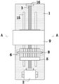
FIG. 2 is a schematic view of the present invention taken along line A-A of FIG. 1;
fig. 3 is a schematic view of the connection structure between the movable seat and the baffle of the present invention.
Detailed Description
The invention is further described with reference to the following figures and specific embodiments.
Referring to fig. 1-3, the groove milling device for knitting needle production and processing of the present invention comprises a frame 1, a servo motor 2 is installed at the middle of the front end of the table top of the frame 1 through a bolt, a ball screw pair 3 is installed at the output end of the servo motor 2 through a shaft coupling, a ball screw nut pair 301 is installed on the outer wall of the ball screw pair 3 in pairs, two moving seats 4 are welded on the top wall of the ball screw nut pair 301, the moving seats 4 are connected with the table top of the frame 1 in a sliding manner, arc-shaped grooves 401 for accommodating knitting needles are also equidistantly formed on the upper portion of the moving seats 4, baffles 5 are vertically welded on the front end of the upper portion of the moving seats 4 and on the rear end of the upper portion of the moving seats 4 on the front side, tapered grooves 501 matched with the tips of the knitting needles are equally spaced on the opposite sides of the two baffles 5, support, two 6 top end faces of extension board are all vertical to have pneumatic cylinder 7, two install depression bar 8 through the screw jointly between 7 tops of pneumatic cylinder, 8 bottom equidistance of depression bar seted up with arc trench 401 assorted arc draw-in groove 801, 1 left side mid-weld of frame has L shape support 9, there is cylinder block 10 bottom in the L shape support 9 through the screw installation, 10 ends of cylinder block have fly leaf 11 through the screw installation, the milling flutes equipment drive main part 12, every is installed from a left side to right equidistance to fly leaf 11 bottom face milling flutes equipment drive main part 12 bottom all installs milling flutes cutter 13 through fastening bolt. Two equal vertical welding in the left and right sides of removal seat 4 bottom has slide bar 14, slide rail 15 with slide bar 14 assorted has all been seted up to the left and right sides on the 1 mesa of frame, removal seat 4 passes through slide bar 14 and links to each other with slide rail 15 sliding connection on the 1 mesa of frame. The hydraulic cylinders 7 on the left side and the right side of each movable seat 4 run synchronously, all the hydraulic cylinders 7 contract to the bottommost position, the pressing rods 8 are in contact with the upper end face of the movable seat 4, and the length of each pressing rod 8 is larger than the width of the upper surface of the movable seat 4. All the groove milling equipment driving main bodies 12 are identical in specification, all the groove milling cutters 13 are identical in specification, and all the groove milling equipment driving main bodies 12 are connected in series through leads and connected with an external controller. Auxiliary plates 16 are vertically welded in the middle of the rear end of the table board of the machine base 1, and the tail ends of the ball screw pairs 3 are rotatably connected with the auxiliary plates 16 through bearings. Anti-skid rubber pads are adhered to four corners of the bottom of the machine base 1, and the thickness of each anti-skid rubber pad is 2 MM.
In order to better understand the utility model by those skilled in the art, the working process of the utility model is briefly described with reference to the attached drawings: firstly, a plurality of knitting needles needing to cut slotted holes are uniformly placed on an arc groove position 401 corresponding to the upper surface of a moving seat 4, the tip parts of the knitting needles are correspondingly inserted at a conical groove 501 of a baffle plate 5, then a pressure rod 8 is driven by two hydraulic cylinders 7 which synchronously run to move downwards, arc-shaped clamping grooves 801 matched with the arc groove position 401 are equidistantly formed in the bottom of the pressure rod 8, so that the upper and lower walls of the plurality of knitting needles which are uniformly placed can be abutted and fixed by utilizing the mutual matching of the arc-shaped clamping grooves 801 and the arc groove position 401, a plurality of knitting needles can be clamped and fixed at one time, a ball screw pair 3 can be driven by a servo motor 2 to rotate, so that two moving seats 4 can be driven to move back and forth by utilizing ball screw nut pairs 301 which are arranged in pairs on the outer wall of the ball screw pair 3, when the knitting needle on the upper part of the moving seat 4 on the rear, the servo motor 2 is controlled to stop running by an external controller, the cylinder body 10 is controlled to drive the movable plate 11 to move downwards, and the groove milling equipment driving main body 12 drives the groove milling cutter 13 to cut the groove holes of the corresponding knitting needles, so that a plurality of knitting needles can be processed at one time, and the groove milling efficiency of the knitting needles is improved.
It should be noted that the specific models of the servo motor 2, the hydraulic cylinder 7, the cylinder block 10, and the groove milling device driving body 12 need to be calculated according to the specific specification of the setting, and the corresponding calculation method belongs to the prior art in the field, and therefore, the description thereof is omitted.
The control modes of the servo motor 2, the hydraulic cylinder 7, the cylinder block 10 and the slot milling device driving body 12, which have been described above, are controlled by a controller, and the specific control modes and the principles thereof are clear to those skilled in the art and will not be described in detail herein.
The basic principles, main features and advantages of the present invention have been shown and described above. It will be understood by those skilled in the art that the present invention is not limited to the above embodiments, and that the foregoing embodiments and descriptions are provided only to illustrate the principles of the present invention without departing from the spirit and scope of the present invention. The scope of the invention is defined by the appended claims and equivalents thereof.
Claims (6)
1. The utility model provides a knitting needle production and processing is with milling flutes device, includes the frame, its characterized in that: the middle part of the front end of the machine base table surface is provided with a servo motor through a bolt, the output end of the servo motor is provided with a ball screw pair through a coupler, the outer wall of the ball screw pair is provided with a ball screw nut pair in pair, the top walls of the two ball screw nut pairs are welded with a moving base, the moving base is connected with the machine base table surface in a sliding way, the upper part of the moving base is also provided with arc groove positions for accommodating knitting needles at equal intervals, the front end and the rear end of the upper part of the moving base at the front side are vertically welded with baffles, the opposite sides of the two baffles are provided with cone grooves matched with the tips of the knitting needles at equal intervals, the lower parts of the left outer wall and the right outer wall of the moving base are horizontally welded with support plates, the top end surfaces of the two support plates are vertically provided with hydraulic cylinders through screws, a pressure rod is jointly installed, frame left side middle part welding has L shape support, there is the cylinder block bottom in the L shape support through the mounting screw, there is the fly leaf at the cylinder block end through the mounting screw, the groove milling equipment drive main part is installed to fly leaf bottom face from a left side to right equidistance, every groove milling equipment drive main part bottom all installs the groove milling cutter through fastening bolt.
2. A groove milling apparatus for manufacturing a knitting needle according to claim 1, wherein: two the equal vertical welding in removal seat bottom left and right sides has the slide bar, the left and right sides on the frame mesa all seted up with slide bar assorted slide rail, it connects continuously through the slide rail sliding on slide bar and the frame mesa to remove the seat.
3. A groove milling apparatus for manufacturing a knitting needle according to claim 1, wherein: every the pneumatic cylinder of the removal seat left and right sides all synchronous operation, all depression bar and removal seat up end in the time of the pneumatic cylinder shrink to the bottommost department contact each other, the length of depression bar is greater than the width of removing the seat upper surface.
4. A groove milling apparatus for manufacturing a knitting needle according to claim 1, wherein: all the groove milling equipment driving main bodies have the same specification, all the groove milling cutters have the same specification, and all the groove milling equipment driving main bodies are connected in series through leads and connected with an external controller.
5. A groove milling apparatus for manufacturing a knitting needle according to claim 1, wherein: auxiliary plates are vertically welded in the middle of the rear end of the platform surface of the machine base, and the tail ends of the ball screw pairs are rotatably connected with the auxiliary plates through bearings.
6. A groove milling apparatus for manufacturing a knitting needle according to claim 1, wherein: anti-skid rubber pads are adhered to four corners of the bottom of the machine base, and the thickness of each anti-skid rubber pad is 2 MM.
Priority Applications (1)
| Application Number | Priority Date | Filing Date | Title |
|---|---|---|---|
| CN201921105966.6U CN210334500U (en) | 2019-07-16 | 2019-07-16 | Groove milling device for production and processing of knitting needles |
Applications Claiming Priority (1)
| Application Number | Priority Date | Filing Date | Title |
|---|---|---|---|
| CN201921105966.6U CN210334500U (en) | 2019-07-16 | 2019-07-16 | Groove milling device for production and processing of knitting needles |
Publications (1)
| Publication Number | Publication Date |
|---|---|
| CN210334500U true CN210334500U (en) | 2020-04-17 |
Family
ID=70195684
Family Applications (1)
| Application Number | Title | Priority Date | Filing Date |
|---|---|---|---|
| CN201921105966.6U Expired - Fee Related CN210334500U (en) | 2019-07-16 | 2019-07-16 | Groove milling device for production and processing of knitting needles |
Country Status (1)
| Country | Link |
|---|---|
| CN (1) | CN210334500U (en) |
Cited By (1)
| Publication number | Priority date | Publication date | Assignee | Title |
|---|---|---|---|---|
| CN115570191A (en) * | 2022-09-30 | 2023-01-06 | 绍兴展泰机械有限公司 | Groove milling device of circular knitting machine needle cylinder |
-
2019
- 2019-07-16 CN CN201921105966.6U patent/CN210334500U/en not_active Expired - Fee Related
Cited By (1)
| Publication number | Priority date | Publication date | Assignee | Title |
|---|---|---|---|---|
| CN115570191A (en) * | 2022-09-30 | 2023-01-06 | 绍兴展泰机械有限公司 | Groove milling device of circular knitting machine needle cylinder |
Similar Documents
| Publication | Publication Date | Title |
|---|---|---|
| CN210334500U (en) | Groove milling device for production and processing of knitting needles | |
| CN214264637U (en) | Full-automatic feeding, drilling, tapping and sawing all-in-one machine | |
| CN211101005U (en) | Extrusion device for machining of mechanical parts | |
| CN214871226U (en) | Plank drilling equipment | |
| CN216326810U (en) | Double-station cutting machine tool magazine | |
| CN215200815U (en) | Flat plate wire clamp tool | |
| CN112720879B (en) | A cutting device for building stones panel processing based on thing networking | |
| CN211439633U (en) | Combined machining workbench | |
| CN211891227U (en) | Turnover mechanism of engraving and milling machine | |
| CN212496629U (en) | Rapid workpiece changing device for slotting machine machining | |
| CN212329768U (en) | High-precision full-automatic four-side milling machine hydraulic fixing device | |
| CN209038003U (en) | A kind of automatic hot cutting open device | |
| CN215315894U (en) | Numerical control lathe for efficiently machining cylindrical surface | |
| CN209954016U (en) | Laser cutting device | |
| CN105773245A (en) | Pneumatic full-automatic positioning clamping equipment for milling side surface of industrial sewing machine D shaft sleeve | |
| CN215700511U (en) | Grinding machine positioning jig | |
| CN220240743U (en) | Anchor clamps fixed establishment of digit control machine tool | |
| CN214023868U (en) | High-efficient vertical groover | |
| CN218081105U (en) | Welding device for machining mining machinery parts | |
| CN217702528U (en) | Five-axis horizontal type plate turnover machining center | |
| CN212917960U (en) | Die cavity line cutting jig | |
| CN216264064U (en) | Automatic carving device that gets of car bearing | |
| CN216967349U (en) | Grinder with operation platform | |
| CN218461511U (en) | Adjustable clamping structure for machining mechanical parts | |
| CN216706014U (en) | Four-boring-rod symmetrical feeding device |
Legal Events
| Date | Code | Title | Description |
|---|---|---|---|
| GR01 | Patent grant | ||
| GR01 | Patent grant | ||
| CF01 | Termination of patent right due to non-payment of annual fee | ||
| CF01 | Termination of patent right due to non-payment of annual fee |
Granted publication date: 20200417 Termination date: 20210716 |