CN210312733U - Automatic pushing mechanism of splitting machine - Google Patents
Automatic pushing mechanism of splitting machine Download PDFInfo
- Publication number
- CN210312733U CN210312733U CN201920798035.2U CN201920798035U CN210312733U CN 210312733 U CN210312733 U CN 210312733U CN 201920798035 U CN201920798035 U CN 201920798035U CN 210312733 U CN210312733 U CN 210312733U
- Authority
- CN
- China
- Prior art keywords
- pushing
- lead screw
- material pushing
- splitting machine
- arm
- Prior art date
- Legal status (The legal status is an assumption and is not a legal conclusion. Google has not performed a legal analysis and makes no representation as to the accuracy of the status listed.)
- Active
Links
Images

Abstract
The utility model discloses an automatic pushing mechanism of a splitting machine, which relates to the field of film splitting equipment and comprises a pushing frame arranged corresponding to a winding shaft of the splitting machine and a pushing arm used for pushing a film roll, wherein a lead screw arranged along the length direction of the winding shaft is arranged in the pushing frame, a lead screw nut is arranged on the lead screw, a connecting seat is arranged on the lead screw nut, and the pushing arm is connected on the connecting seat; the material pushing frame is provided with two parallel first guide rails, and the connecting seat is connected to the first guide rails in a sliding manner through a sliding block; the screw rod is connected with a first power mechanism, and the first power mechanism drives the screw rod to rotate. The utility model discloses a be provided with the lead screw in the work or material rest, the lead screw drives through screw nut under first power unit's drive and pushes away the material arm and remove along rolling axle length direction, releases the completion with the good film book of rolling from the rolling epaxial and unloads, realizes that machinery replaces artifical unloading, alleviates intensity of labour, and the film book can reach the maximum load of rolling axle and carry out the unloading again, improves production efficiency.
Description
Technical Field
The utility model relates to an equipment field, especially an automatic pushing equipment of cutting machine are cut to film.
Background
The splitting machine is suitable for high-speed splitting operation of various paper films such as centrifugal paper and the like. Although the existing splitting machine has high splitting speed, the film is unloaded manually, the film is wound on a winding core again to form a film roll after being split, and the wound film roll needs to be manually taken down from a winding shaft of the splitting machine.
SUMMERY OF THE UTILITY MODEL
The present invention aims to solve at least one of the above-mentioned technical problems in the related art to a certain extent. Therefore, the utility model provides a can realize automatic unloading, improve production efficiency, alleviate intensity of labour's automatic pushing equipment of cutting machine.
The utility model provides an automatic pushing mechanism of a splitting machine, which comprises a pushing frame arranged corresponding to a winding shaft of the splitting machine and a pushing arm used for pushing a film roll, wherein a lead screw arranged along the length direction of the winding shaft is arranged in the pushing frame, a lead screw nut is arranged on the lead screw, a connecting seat is arranged on the lead screw nut, and the pushing arm is connected on the connecting seat; the material pushing frame is provided with two parallel first guide rails, and the connecting seat is connected to the first guide rails in a sliding manner through a sliding block; the screw rod is connected with a first power mechanism, and the first power mechanism drives the screw rod to rotate.
Above-mentioned automatic pushing equipment of cutting machine has following beneficial effect at least: the lead screw arranged along the length direction of the winding shaft is arranged in the material pushing frame, the lead screw drives the material pushing arm to move along the length direction of the winding shaft through the lead screw nut under the driving of the first power mechanism, and the wound film roll is pushed out of the winding shaft to finish discharging, so that the manual discharging is replaced by machinery, and the labor intensity is reduced; the machine replaces manual pushing and unloading, and can unload the film roll after the film roll reaches the maximum load of the winding shaft, so that the production efficiency is improved. The utility model has the advantages of being scientific and reasonable in structural design, replace the manual work to push away the material and unload through machinery, realize automatic unloading, alleviate intensity of labour, improve production efficiency.
According to an automatic pushing equipment of cutting machine, be provided with the recess that is used for dodging the convex of rolling axle on the material pushing arm. The size of the groove is larger than the diameter of the winding shaft, and the pushing arm can avoid the winding shaft through the groove, so that the film roll is pushed out of the winding shaft to complete discharging.
According to an automatic pushing equipment of cutting machine, push away and correspond on the material arm the position of recess is provided with and pushes away the material piece, when pushing away the material, push away the book core terminal surface looks butt that material piece and film were rolled up. The film pushing device is arranged in such a way that in the discharging process, the pushing piece is abutted to the end face of the winding core, the pushing piece applies force to the end face of the winding core, and the film wound on the winding core is pushed out together to complete discharging. The pushing piece is prevented from directly applying force on the film, so that the film moves relative to the winding core and the integrity of a finished film roll is damaged.
According to an automatic pushing equipment of cutting machine, first power unit is gear motor, the right-hand member of pushing away the work or material rest is provided with the motor cabinet, gear motor sets up on the motor cabinet to through the shaft coupling with screw connection. The speed reducing motor has the characteristics of compact structure, small volume, strong overload bearing capacity, low energy consumption, excellent performance, small vibration, low noise, convenient maintenance and the like. The gear motor is arranged at the right end of the material pushing frame and is directly connected with the lead screw through the coupler, an additional speed reducing device is not needed, and the whole mechanism is more compact and more miniaturized.
According to a cutting machine's automatic pushing equipment, the lead screw pass through flange bearing with the work or material rest is connected. The stability of the screw rod is improved by using the flange bearing, and the problem that the screw rod vibrates to influence the smoothness of pushing materials in the pushing process is avoided.
According to automatic pushing equipment of cutting machine, push away work or material rest both ends and be provided with the sensor, the sensor electricity is connected with the controller, first power unit with the controller electricity is connected. According to the arrangement, when the pushing arm completely pushes out the film roll to complete unloading, the sensor on the left side of the pushing frame detects the pushing arm and transmits a signal to the controller, and the controller controls the first power mechanism to rotate reversely to enable the pushing arm to reset. When the sensor on the right side of the material pushing frame detects that the material pushing arm returns to the initial position, the sensor transmits a signal to the controller, and the controller controls the first power mechanism to stop running. The material pushing arm can reciprocate on the screw rod.
Drawings
The present invention will be further explained with reference to the drawings and examples.
Fig. 1 is a schematic structural diagram of an embodiment of an automatic pushing mechanism of a splitting machine according to the present invention;
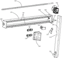
fig. 2 is a schematic view of an exploded structure of an embodiment of an automatic pushing mechanism of the splitting machine of the present invention.
Detailed Description
Referring to fig. 1-2, an automatic pushing mechanism of a splitting machine according to an embodiment of the present invention includes a pushing frame 100 corresponding to a winding shaft of the splitting machine and a pushing arm 200 for pushing a film roll, a lead screw 300 disposed along a length direction of the winding shaft is disposed in the pushing frame 100, the lead screw 300 is provided with a lead screw nut 400, the lead screw nut 400 is provided with a connecting seat 500, and the pushing arm 200 is connected to the connecting seat 500; the material pushing frame 100 is provided with two parallel first guide rails 110, and the connecting seat 500 is slidably connected to the first guide rails 110 through the sliding blocks 510; the screw 300 is connected with a first power mechanism, and the first power mechanism drives the screw 300 to rotate. Compared with the prior art, the embodiment of the utility model has the advantages that the lead screw 300 arranged along the length direction of the winding shaft is arranged in the material pushing frame 100, the lead screw 300 is driven by the first power mechanism to drive the material pushing arm 200 to move along the length direction of the winding shaft through the lead screw nut 400, and the wound film roll is pushed out from the winding shaft to complete unloading, so that the manual blanking is replaced by machinery, and the labor intensity is reduced; the machine replaces manual pushing and unloading, and unloading can be carried out when the film roll reaches the maximum load of the winding shaft, so that the production efficiency is improved; through sliding the connecting seat 500 on the first guide rail 110, the rotation of the screw nut 400 can be avoided, and when the first power mechanism drives the screw 300 to rotate, the screw nut 400 drives the material pushing arm 200 to move along the length direction of the winding shaft. The first guide rail 110 plays a role in guiding and positioning the connecting seat 500, so that the pushing arm 200 can move smoothly along the length direction of the winding shaft in the pushing process, and the film roll can be completely discharged. The embodiment of the utility model provides a structural design scientific and reasonable replaces the manual work to push away the material and unloads through machinery, realizes automatic unloading, alleviates intensity of labour, improves production efficiency. It should be noted that, the rolling axle of cutting machine is that one end is connected with the cutting machine, and the other end is unsettled, and the cutting machine corresponds the flexible support piece that is provided with of rolling axle free end, and support piece is flexible by first cylinder drive, and when the rolling axle drove the book core and rotates the rolling, first cylinder drive support piece stretched out with the free end butt of rolling axle, supports the free end of rolling axle at the rolling in-process, avoids the rolling axle to warp. A bracket is arranged at the free end corresponding to the winding shaft, and a material receiving shaft matched with the winding shaft is rotatably connected to the bracket. During discharging, the material receiving shaft is rotated to be in butt joint with the suspended end of the winding shaft, the first air cylinder drives the supporting plate to retract, then the first power mechanism drives the screw rod 300 to drive the material pushing arm 200 to move along the length direction of the winding shaft, and a wound film roll is pushed out of the winding shaft and pushed onto the material receiving shaft. After pushing, the pushing arm 200 is reset, the receiving shaft is rotated to be separated from the winding shaft, and then a new winding core is loaded into the winding shaft for the next winding.
Preferably, the material pushing arm 200 is provided with a circular arc-shaped groove 210 for avoiding the winding shaft. The size of the groove 210 is larger than the diameter of the winding shaft, and the pushing arm 200 can avoid the winding shaft through the groove 210, so that the film roll is pushed out from the winding shaft to complete discharging.
The material pushing arm 200 is provided with a material pushing member 220 at a position corresponding to the groove 210, and when pushing material, the material pushing member 220 abuts against the end face of the winding core of the film roll. By the arrangement, in the discharging process, the pushing element 220 is abutted to the end face of the winding core, the pushing element 220 applies force to the end face of the winding core, and the film wound on the winding core is pushed out together to complete discharging. The pushing part 220 is prevented from directly applying force on the film, so that the film moves relative to the winding core and the integrity of the finished film roll is damaged. Specifically, be provided with two rolling axles on the cutting machine, push away and be provided with two recesses 210 that correspond with the rolling axle on the material arm 200, it is corresponding, push away material piece 220 and be provided with two, set up like this, once the action can be released the good film book of rolling on two rolling axles, accomplishes the unloading, improves production efficiency. Of course, the grooves 210 and the stripper members 220 may be provided in other numbers as desired for production.
Preferably, the first power mechanism is a speed reduction motor 700, the right end of the material pushing frame 100 is provided with a motor base 130, and the speed reduction motor 700 is arranged on the motor base 130 and connected with the lead screw 300 through a coupler. The speed reducing motor 700 has the characteristics of compact structure, small volume, strong overload bearing capacity, low energy consumption, excellent performance, small vibration, low noise, convenient maintenance and the like. The gear motor 700 is arranged at the right end of the material pushing frame 100 and is directly connected with the lead screw 300 through a coupler, and an additional speed reducing device is not needed, so that the whole mechanism is more compact and more miniaturized. Of course, the first power mechanism may also be selected from other types of motors or other power mechanisms, such as a servo motor, a stepping motor, etc., according to the actual production requirements. Further, the motor base 130 includes a horizontal section 132 and a vertical section 131, the vertical section 131 is connected to the material pushing frame 100 through the support 900, a reinforcing rib 133 is disposed between the horizontal section 132 and the vertical section 131, the reinforcing rib 133 increases the bearing capacity of the motor base 130, and prevents the horizontal section 132 from being deformed by the weight of the reducing motor 700, so as to affect the maximum torque transmitted by the reducing motor 700 to the lead screw 300.
Preferably, the lead screw 300 is connected with the pusher frame 100 through a flange bearing 800. The stability of the screw 300 is improved by using the flange bearing 800, and the problem that the screw 300 vibrates to influence the smoothness of pushing materials in the process of pushing materials is avoided.
Preferably, sensors are arranged at two ends of the material pushing frame 100, the sensors are electrically connected with a controller, and the first power mechanism is electrically connected with the controller. With the arrangement, when the pushing arm 200 completely pushes out the film roll to complete discharging, the sensor on the left side of the pushing frame 100 detects the pushing arm 200 and transmits a signal to the controller, and the controller controls the first power mechanism to rotate reversely to reset the pushing arm 200. When the sensor on the right side of the material pushing frame 100 detects that the material pushing arm 200 returns to the initial position, a signal is transmitted to the controller, and the controller controls the first power mechanism to stop running. The reciprocating motion of the pushing arm 200 on the lead screw 300 is realized.
The above is only a preferred embodiment of the present invention, and is not intended to limit the present invention, and those skilled in the art can make various modifications and variations; any modification, equivalent replacement, or improvement made within the spirit and principle of the present invention should be included in the protection scope of the present invention.
Claims (6)
1. The utility model provides an automatic pushing equipment of cutting machine which characterized in that: the film roll pushing device comprises a material pushing frame (100) and a material pushing arm (200), wherein the material pushing frame (100) corresponds to a winding shaft of a splitting machine, the material pushing arm is used for pushing a film roll out, a lead screw (300) is arranged in the material pushing frame (100) along the length direction of the winding shaft, a lead screw nut (400) is arranged on the lead screw (300), a connecting seat (500) is arranged on the lead screw nut (400), and the material pushing arm (200) is connected to the connecting seat (500); the material pushing frame (100) is provided with two parallel first guide rails (110), and the connecting seat (500) is connected to the first guide rails (110) in a sliding manner through sliding blocks (510); the lead screw (300) is connected with a first power mechanism, and the first power mechanism drives the lead screw (300) to rotate.
2. The automatic pushing mechanism of the splitting machine as claimed in claim 1, wherein: and a circular arc-shaped groove (210) for avoiding the winding shaft is formed in the material pushing arm (200).
3. The automatic pushing mechanism of the splitting machine as claimed in claim 2, wherein: the material pushing arm (200) is provided with a material pushing part (220) at a position corresponding to the groove (210), and when pushing materials, the material pushing part (220) is abutted against the end face of the winding core of the film roll.
4. The automatic pushing mechanism of the splitting machine as claimed in claim 1, wherein: the first power mechanism is a speed reducing motor (700), the right end of the material pushing frame (100) is provided with a motor base (130), and the speed reducing motor (700) is arranged on the motor base (130) and connected with the lead screw (300) through a coupler.
5. The automatic pushing mechanism of the splitting machine as claimed in claim 1, wherein: the lead screw (300) is connected with the material pushing frame (100) through a flange bearing (800).
6. The automatic pushing mechanism of the splitting machine as claimed in claim 1, wherein: sensors are arranged at two ends of the material pushing frame (100), the sensors are electrically connected with a controller, and the first power mechanism is electrically connected with the controller.
Priority Applications (1)
| Application Number | Priority Date | Filing Date | Title |
|---|---|---|---|
| CN201920798035.2U CN210312733U (en) | 2019-05-28 | 2019-05-28 | Automatic pushing mechanism of splitting machine |
Applications Claiming Priority (1)
| Application Number | Priority Date | Filing Date | Title |
|---|---|---|---|
| CN201920798035.2U CN210312733U (en) | 2019-05-28 | 2019-05-28 | Automatic pushing mechanism of splitting machine |
Publications (1)
| Publication Number | Publication Date |
|---|---|
| CN210312733U true CN210312733U (en) | 2020-04-14 |
Family
ID=70141141
Family Applications (1)
| Application Number | Title | Priority Date | Filing Date |
|---|---|---|---|
| CN201920798035.2U Active CN210312733U (en) | 2019-05-28 | 2019-05-28 | Automatic pushing mechanism of splitting machine |
Country Status (1)
| Country | Link |
|---|---|
| CN (1) | CN210312733U (en) |
Cited By (2)
| Publication number | Priority date | Publication date | Assignee | Title |
|---|---|---|---|---|
| CN112093554A (en) * | 2020-09-16 | 2020-12-18 | 黄山三夏精密机械有限公司 | Central surface rolling and splitting machine |
| CN113955565A (en) * | 2021-10-25 | 2022-01-21 | 苍南县凌峰包装机械有限公司 | Splitting machine |
-
2019
- 2019-05-28 CN CN201920798035.2U patent/CN210312733U/en active Active
Cited By (3)
| Publication number | Priority date | Publication date | Assignee | Title |
|---|---|---|---|---|
| CN112093554A (en) * | 2020-09-16 | 2020-12-18 | 黄山三夏精密机械有限公司 | Central surface rolling and splitting machine |
| CN112093554B (en) * | 2020-09-16 | 2022-07-05 | 黄山三夏精密机械有限公司 | Central surface rolling and splitting machine |
| CN113955565A (en) * | 2021-10-25 | 2022-01-21 | 苍南县凌峰包装机械有限公司 | Splitting machine |
Similar Documents
| Publication | Publication Date | Title |
|---|---|---|
| CN210312733U (en) | Automatic pushing mechanism of splitting machine | |
| CN103633375B (en) | A kind of lithium battery electric core process equipment | |
| CN109573698B (en) | Automatic winding device of PVB film production line | |
| CN212668847U (en) | Cable winding structure | |
| CN216511786U (en) | Automatic foil coiling device for electrode foil | |
| CN208743811U (en) | Full-automatic section bar cutting machine | |
| CN107585611A (en) | A kind of cutting structure of film cutting winder | |
| CN210192915U (en) | Ultrathin nanocrystalline strip winder | |
| CN107651478A (en) | A kind of winding structure of film cutting winder | |
| CN208199912U (en) | A kind of automatic rolling device of woven bag | |
| CN215149455U (en) | Cutting mechanism of slitter for rubber product processing | |
| CN212608381U (en) | Composite fabric winding and blanking device | |
| CN214166801U (en) | Unloader of coating machine | |
| CN206634836U (en) | A kind of adjustable slitting equipment of adhesive tape | |
| CN220684247U (en) | Winding machine with cutting structure | |
| CN215797507U (en) | Adhesive tape cutting, rolling and flattening device | |
| CN201084778Y (en) | A full-automatic pole piece rubberizing mechanism | |
| CN219469139U (en) | Waterproof cloth rolling device | |
| CN112757804B (en) | Upper bookcase device for uniform division and accompanying pressing | |
| CN220864412U (en) | Diamond wire slicing and conducting wire device | |
| CN219771295U (en) | Automatic material receiving structure of rolling for coating machine | |
| CN219636665U (en) | Tape winder with tapering stock structure | |
| CN212739999U (en) | Double-station automatic winding machine | |
| CN220638090U (en) | TPU film generates side cut device | |
| CN213011015U (en) | Divide strip quick-witted coiling mechanism |
Legal Events
| Date | Code | Title | Description |
|---|---|---|---|
| GR01 | Patent grant | ||
| GR01 | Patent grant |