CN210308048U - Shuttle peg cover processing drilling equipment - Google Patents
Shuttle peg cover processing drilling equipment Download PDFInfo
- Publication number
- CN210308048U CN210308048U CN201921261673.7U CN201921261673U CN210308048U CN 210308048 U CN210308048 U CN 210308048U CN 201921261673 U CN201921261673 U CN 201921261673U CN 210308048 U CN210308048 U CN 210308048U
- Authority
- CN
- China
- Prior art keywords
- bobbin case
- connecting block
- punching device
- case processing
- punching
- Prior art date
- Legal status (The legal status is an assumption and is not a legal conclusion. Google has not performed a legal analysis and makes no representation as to the accuracy of the status listed.)
- Active
Links
Images


Abstract
The utility model discloses a bobbin case processing and punching device, which comprises a damping base and a support rod, wherein the bobbin case to be punched is fixed on a fixing device, the fixing device of the utility model is provided with a plurality of fixing ports, a plurality of bobbin cases can be simultaneously fixed by utilizing the plurality of fixing ports, and four driven rotating shafts arranged on the punching device are matched, so that four bobbin cases can be simultaneously punched, the time for installation and disassembly is reduced, the working efficiency can be effectively improved, the damping base is arranged at the bottom of the utility model, the common action of an elastic spring and a strong spring arranged in the damping base is facilitated, the device has good damping effect, the device can have good buffering effect when the device is punched, the damping effect is facilitated to be improved, the stable operation of the device is ensured, and the punching accuracy is improved, the noise generated by vibration is reduced while the vibration strength is reduced.
Description
Technical Field
The utility model belongs to the technical field of punch and relate to a shuttle peg cover processing drilling equipment.
Background
The bobbin case processing and punching equipment is mechanical equipment used for punching the bobbin case.
The prior bobbin case processing and punching equipment has the following problems:
1. current bobbin cover processing drilling equipment does not have damping device usually, carries out the during operation at equipment, and equipment such as motors can produce vibrations, can influence the precision of punching, can produce the noise simultaneously, influences the efficiency of punching.
2. The existing bobbin case processing and punching equipment can only punch one bobbin case at a time, needs to be repeatedly installed, fixed, disassembled and replaced, wastes time and has lower working efficiency.
SUMMERY OF THE UTILITY MODEL
An object of the utility model is to provide a shuttle peg cover processing drilling equipment to the lower and lower problem of work efficiency of the precision of punching that proposes among the above-mentioned background art is solved.
In order to achieve the above object, the utility model provides a following technical scheme: the utility model provides a shuttle peg cover processing drilling equipment, includes vibration damping mount and branch, the last branch that is provided with of vibration damping mount, be provided with elevating gear on the branch, the last horizontal tray that is provided with of elevating gear, be provided with fixing device on the tray, the top of branch is provided with the work box, the right side position department of work box bottom is provided with the motor, and the left side position department of work box bottom is provided with transmission, transmission's bottom is provided with perforating device, be provided with the lift handle on the side of work box.
Preferably, perforating device includes vertical drive belt, initiative pivot, transverse transmission belt, driven spindle and the dish of punching, the intermediate position department of the dish of punching is provided with the initiative pivot, be provided with four driven spindles around the initiative pivot, connect through vertical drive belt transmission between initiative pivot and two fore-and-aft driven spindles, connect through transverse transmission belt transmission between initiative pivot and two fore-and-aft driven spindles.
Preferably, fixing device includes fixed mouthful, installation pole, plate body and fastener, the middle part and the four corners department of plate body all are provided with the installation pole, and are provided with four fixed mouths, four on the plate body the outside of fixed mouthful all is provided with the fastener.
Preferably, vibration damping mount includes connecting block, shell, bracing piece, goes up connecting block, elastic spring, backing plate and powerful spring down, be provided with the shell down on the connecting block, be provided with powerful spring in the shell, powerful spring's top is provided with the bracing piece, the top of bracing piece is provided with the backing plate, be provided with elastic spring on the backing plate, elastic spring's top is provided with the connecting block.
Preferably, the motor is Y80M 1-2.
Preferably, the four driven rotating shafts are the same in size and shape, and the longitudinal transmission belt and the transverse transmission belt are the same in length and specification.
Preferably, the four fixing openings are identical in size and shape, the five mounting rods are identical in length and shape, and the four fastening pieces are identical in structure and size.
Preferably, the elastic coefficient of the elastic spring and the elastic coefficient of the strong spring are good, and the shape and the size of the upper connecting block and the lower connecting block are the same.
Compared with the prior art, the utility model provides a shuttle peg cover processing drilling equipment possesses following beneficial effect: 1. will the utility model discloses with external power source electric connection, then fix the shuttle peg cover that will punch on fixing device again to can adjust the tray to suitable height through elevating gear, then the motor begins to work, makes transmission rotate, thereby drives perforating device and carries out work, the utility model discloses be provided with a plurality of fixed mouths on the fixing device, utilize a plurality of fixed mouths can fix a plurality of shuttle peg covers simultaneously to four driven rotating shafts that set up on the cooperation perforating device can punch the operation to four shuttle peg covers simultaneously, reduce the time of installation and dismantlement, can effectual improvement work efficiency.
2. The utility model discloses a bottom is provided with vibration damping mount, does benefit to under the combined action of the inside elastic spring that sets up of vibration damping mount and powerful spring, makes equipment have good shock attenuation effect, can play good cushioning effect to equipment when equipment punches the during operation, is favorable to improving the damping effect, ensures the even running of equipment, improves the precision of punching, when having reduced shock strength, has also reduced vibrations and the noise that produces.
Drawings
The accompanying drawings are included to provide a further understanding of the invention, and are incorporated in and constitute a part of this specification, illustrate embodiments of the invention, and together with the description, do not constitute a limitation of the invention, in which:
fig. 1 is a schematic structural view of a bobbin case processing and punching device provided by the present invention;
FIG. 2 is a schematic structural view of the punching device of the present invention;
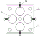
fig. 3 is a schematic structural view of the fixing device of the present invention;
fig. 4 is a schematic structural view of the damping mount provided by the present invention;
in the figure: 1. a transmission device; 2. a punching device; 3. a fixing device; 4. a tray; 5. a damping mount; 6. a strut; 7. a lifting device; 8. a motor; 9. a lifting handle; 10. a work box; 21. a longitudinal drive belt; 22. a driving rotating shaft; 23. a transverse drive belt; 24. a driven rotating shaft; 25. punching a hole disc; 31. a fixed port; 32. mounting a rod; 33. a plate body; 34. a fastener; 51. a lower connecting block; 52. a housing; 53. a support bar; 54. an upper connecting block; 55. an elastic spring; 56. a base plate; 57. a strong spring.
Detailed Description
The technical solutions in the embodiments of the present invention will be described clearly and completely with reference to the accompanying drawings in the embodiments of the present invention, and it is obvious that the described embodiments are only some embodiments of the present invention, not all embodiments. Based on the embodiments in the present invention, all other embodiments obtained by a person skilled in the art without creative work belong to the protection scope of the present invention.
Referring to fig. 1-4, the present invention provides a technical solution: the utility model provides a shuttle peg cover processing drilling equipment, includes vibration damping mount 5 and branch 6, its characterized in that: the damping base 5 is provided with a support rod 6, the damping base 5 comprises a lower connecting block 51, a shell 52, a support rod 53, an upper connecting block 54, an elastic spring 55, a backing plate 56 and a strong spring 57, the lower connecting block 51 is provided with the shell 52, the shell 52 is internally provided with the strong spring 57, the top end of the strong spring 57 is provided with the support rod 53, the top end of the support rod 53 is provided with the backing plate 56, the backing plate 56 is provided with the elastic spring 55, the top end of the elastic spring 55 is provided with the upper connecting block 54, the elastic coefficient of the elastic spring 55 and the strong spring 57 is good, the upper connecting block 54 and the lower connecting block 51 are the same in shape and size, the elastic spring 55 and the strong spring 57 with good elastic coefficients can ensure the stable operation of the equipment, the vibration strength is reduced, the noise generated by vibration is reduced, and the combined action of the elastic spring, make equipment have good shock attenuation effect, can punch the during operation at equipment and play good cushioning effect to equipment, be favorable to improving the damping effect, ensure the even running of equipment.
A bobbin case processing and punching device comprises a supporting rod 6, wherein a lifting device 7 is arranged on the supporting rod 6, a transverse tray 4 is arranged on the lifting device 7, a fixing device 3 is arranged on the tray 4, the fixing device 3 comprises a fixing port 31, mounting rods 32, a plate body 33 and fasteners 34, the mounting rods 32 are arranged at the middle part and the four corners of the plate body 33, the plate body 33 is mounted by the mounting rods 32, four fixing ports 31 are arranged on the plate body 33, the fixing ports 31 are used for fixing the bobbin case, the fasteners 34 are arranged on the outer sides of the four fixing ports 31, the four fixing ports 31 are identical in size and shape, the five mounting rods 32 are identical in length and shape, the four fasteners 34 are identical in structure and size, the bobbin cases with different sizes are fixed by the fixing ports 31, the bobbin cases with different sizes are firmly fixed by the fasteners 34, the bobbin cases with different sizes can be fixed by the fasteners 34, can improve the applicability of the utility model.
A punching device for processing a shuttle peg sleeve comprises a working box 10 arranged at the top end of a supporting rod 6, a motor 8 is arranged at the right side position of the bottom of the working box 10, the model of the motor 8 is Y80M1-2, so that the motor 8 can drive the utility model to normally operate without wasting energy, a transmission device 1 is arranged at the left side position of the bottom of the working box 10, a punching device 2 is arranged at the bottom of the transmission device 1, the punching device 2 comprises a longitudinal transmission belt 21, a driving rotating shaft 22, a transverse transmission belt 23, a driven rotating shaft 24 and a punching disc 25, the driving rotating shaft 22 is arranged at the middle position of the punching disc 25, four driven rotating shafts 24 are arranged around the driving rotating shaft 22, the driving rotating shaft 22 is in transmission connection with the two longitudinal driven rotating shafts 24 through the longitudinal transmission belt 21, the driving rotating shaft 22 is in transmission connection with the two transverse driven rotating shafts 24 through the transverse transmission, the size and the shape of four driven spindle 24 are all the same, are convenient for install and change, improve the utility model discloses a practicality, the length and the specification of vertical drive belt 21 and transverse transmission belt 23 are all the same, are convenient for install and change vertical drive belt 21 and transverse transmission belt 23, utilize initiative pivot 22 to drive four driven spindle 24 and move, can reduce the energy loss, are provided with lifting handle 9 on the side of work box 10.
The utility model discloses a theory of operation and use flow: after the utility model is installed, a user firstly checks whether the external appearance of the utility model is complete or not, confirms that the utility model is in a normal working state, then the user moves the utility model to a position where the utility model is needed to be used, electrically connects the utility model with an external power supply, then fixes the shuttle core sleeve needing to be punched on the fixing device 3, and can adjust the tray 4 to a proper height through the lifting device 7, then the motor 8 starts to work, so that the transmission device 1 rotates, thereby driving the punching device 2 to work, the fixing device 3 of the utility model is provided with a plurality of fixing ports 31, a plurality of shuttle core sleeves can be fixed simultaneously by utilizing a plurality of fixing ports 31, and the four driven rotating shafts 24 arranged on the punching device 2 are matched, thereby punching operation can be carried out on four shuttle core sleeves simultaneously, and the time for installation and disassembly is reduced, can effectual improvement work efficiency, be simultaneously the utility model discloses a bottom is provided with vibration damping mount 5, does benefit to under the combined action of the inside elastic spring 55 that sets up of vibration damping mount 5 and powerful spring 57, makes equipment have good shock attenuation effect, can punch the during operation at equipment and play good cushioning effect to equipment, is favorable to improving the damping effect, ensures the even running of equipment, when having reduced shock strength, has also reduced vibrations and the noise that produces.
Although embodiments of the present invention have been shown and described, it will be appreciated by those skilled in the art that changes, modifications, substitutions and alterations can be made in these embodiments without departing from the principles and spirit of the invention, the scope of which is defined in the appended claims and their equivalents.
Claims (8)
1. The utility model provides a shuttle peg cover processing drilling equipment, includes vibration damping mount (5) and branch (6), its characterized in that: be provided with branch (6) on vibration damping mount (5), be provided with elevating gear (7) on branch (6), be provided with horizontal tray (4) on elevating gear (7), be provided with fixing device (3) on tray (4), the top of branch (6) is provided with work box (10), the right side position department of work box (10) bottom is provided with motor (8), and the left side position department of work box (10) bottom is provided with transmission (1), the bottom of transmission (1) is provided with perforating device (2), be provided with lift handle (9) on the side of work box (10).
2. The bobbin case processing and punching device according to claim 1, wherein: perforating device (2) are including vertical drive belt (21), initiative pivot (22), transverse transmission belt (23), driven spindle (24) and drilling dish (25), the intermediate position department of drilling dish (25) is provided with initiative pivot (22), be provided with four driven spindles (24) around initiative pivot (22), connect through vertical drive belt (21) transmission between initiative pivot (22) and two fore-and-aft driven spindles (24), connect through transverse transmission belt (23) transmission between initiative pivot (22) and two fore-and-aft driven spindles (24).
3. The bobbin case processing and punching device according to claim 1, wherein: fixing device (3) are including fixed mouthful (31), installation pole (32), plate body (33) and fastener (34), the middle part and the four corners department of plate body (33) all are provided with installation pole (32), and are provided with four fixed mouthful (31) on plate body (33), four the outside of fixed mouthful (31) all is provided with fastener (34).
4. The bobbin case processing and punching device according to claim 1, wherein: damping base (5) are including connecting block (51), shell (52), bracing piece (53) down, go up connecting block (54), elastic spring (55), backing plate (56) and powerful spring (57), be provided with shell (52) down on connecting block (51), be provided with powerful spring (57) in shell (52), the top of powerful spring (57) is provided with bracing piece (53), the top of bracing piece (53) is provided with backing plate (56), be provided with elastic spring (55) on backing plate (56), the top of elastic spring (55) is provided with connecting block (54).
5. The bobbin case processing and punching device according to claim 1, wherein: the type of the motor (8) is Y80M 1-2.
6. The bobbin case processing and punching device according to claim 2, wherein: the four driven rotating shafts (24) are identical in size and shape, and the longitudinal transmission belt (21) and the transverse transmission belt (23) are identical in length and specification.
7. The bobbin case processing and punching device according to claim 3, wherein: the four fixing openings (31) are identical in size and shape, the five mounting rods (32) are identical in length and shape, and the four fasteners (34) are identical in structure and size.
8. The bobbin case processing and punching device according to claim 4, wherein: the elastic coefficient of the elastic spring (55) and the elastic coefficient of the strong spring (57) are good, and the shape and the size of the upper connecting block (54) and the lower connecting block (51) are the same.
Priority Applications (1)
| Application Number | Priority Date | Filing Date | Title |
|---|---|---|---|
| CN201921261673.7U CN210308048U (en) | 2019-08-06 | 2019-08-06 | Shuttle peg cover processing drilling equipment |
Applications Claiming Priority (1)
| Application Number | Priority Date | Filing Date | Title |
|---|---|---|---|
| CN201921261673.7U CN210308048U (en) | 2019-08-06 | 2019-08-06 | Shuttle peg cover processing drilling equipment |
Publications (1)
| Publication Number | Publication Date |
|---|---|
| CN210308048U true CN210308048U (en) | 2020-04-14 |
Family
ID=70128312
Family Applications (1)
| Application Number | Title | Priority Date | Filing Date |
|---|---|---|---|
| CN201921261673.7U Active CN210308048U (en) | 2019-08-06 | 2019-08-06 | Shuttle peg cover processing drilling equipment |
Country Status (1)
| Country | Link |
|---|---|
| CN (1) | CN210308048U (en) |
Cited By (1)
| Publication number | Priority date | Publication date | Assignee | Title |
|---|---|---|---|---|
| CN114749551A (en) * | 2022-05-06 | 2022-07-15 | 宁波鸿云精密机械有限公司 | Punching equipment for machining bobbin case |
-
2019
- 2019-08-06 CN CN201921261673.7U patent/CN210308048U/en active Active
Cited By (1)
| Publication number | Priority date | Publication date | Assignee | Title |
|---|---|---|---|---|
| CN114749551A (en) * | 2022-05-06 | 2022-07-15 | 宁波鸿云精密机械有限公司 | Punching equipment for machining bobbin case |
Similar Documents
| Publication | Publication Date | Title |
|---|---|---|
| CN210308048U (en) | Shuttle peg cover processing drilling equipment | |
| CN214369084U (en) | Construction simulation device based on BIM technology | |
| CN213288387U (en) | Die structure for bearing manufacturing | |
| CN216290496U (en) | Automatic change transfer apparatus motor mounting panel | |
| CN207580770U (en) | A kind of vibrating disk component for automatic assembly line | |
| CN216162500U (en) | Permanent magnet synchronous motor easy to assemble | |
| CN215394496U (en) | Burnishing device is used in cubical switchboard casing production and processing | |
| CN213521521U (en) | Motor with shock-absorbing function | |
| CN210791557U (en) | Perforating device for construction | |
| CN211266652U (en) | Long-life motor | |
| CN206998843U (en) | A kind of processing base easy to use | |
| CN215267931U (en) | High-efficiency energy-saving motor for robot | |
| CN214887555U (en) | Energy-saving air compressor of bipolar compressor | |
| CN212875556U (en) | Vibration-resistant motor | |
| CN220122710U (en) | Damping type three-phase alternating current permanent magnet synchronous motor | |
| CN215772795U (en) | Motor for refrigeration plant with protect function | |
| CN220475523U (en) | Shock-absorbing structure of motor of reclaimed water outlet pump | |
| CN219852194U (en) | Industrial machinery perforating device | |
| CN213035405U (en) | Shock-absorbing device of paper cup forming machine | |
| CN215698196U (en) | Rotary axle end face punching machine | |
| CN210157573U (en) | Uniform heat dissipation's main frame placer | |
| CN218261800U (en) | Jacking device with shock-absorbing function | |
| CN113107899B (en) | Cooling fan for high-power variable frequency motor | |
| CN218513273U (en) | Single-phase ferronickel stove transformer | |
| CN220279468U (en) | Bearing mounting device |
Legal Events
| Date | Code | Title | Description |
|---|---|---|---|
| GR01 | Patent grant | ||
| GR01 | Patent grant |