Burnishing device is used in cubical switchboard casing production and processing
Technical Field
The utility model relates to the technical field of polishing devices, in particular to a polishing device for producing and processing a switch cabinet shell.
Background
A switch cabinet is an electrical device; the main function of the switch cabinet is to open and close, control and protect electric equipment in the process of power generation, power transmission, power distribution and electric energy conversion of an electric power system. The components in the switch cabinet mainly comprise a circuit breaker, an isolating switch, a load switch, an operating mechanism, a mutual inductor, various protection devices and the like; polishing refers to a process of reducing the roughness of a workpiece surface by mechanical, chemical, or electrochemical actions to obtain a bright, flat surface.
Most of the existing polishing modes for the switch cabinet shell are manual polishing, and the manual polishing is slow in speed and low in efficiency; most of the existing automatic polishing devices are fixed structures, and the height of a polishing component cannot be freely and flexibly adjusted; in addition, the existing polishing device is lack of a damping device and a dust suction device, the lack of the damping device can cause unstable vibration of the device during working, and the lack of the dust suction device can cause environmental pollution and further affect the health of personnel; therefore, a new device is needed to solve the above problems.
SUMMERY OF THE UTILITY MODEL
The utility model aims to provide a polishing device for producing and processing a switch cabinet shell, which aims to solve the problems in the background technology.
In order to achieve the purpose, the utility model provides the following technical scheme:
a polishing device for producing and processing a switch cabinet shell comprises a base, a polishing assembly, a motor and a motor base; the base is of a hollow structure with through holes formed in the left side and the right side of the top; screw rod supports with upper and lower through holes on the side walls are symmetrically and fixedly installed on the edges of the left side and the right side of the top of the base, a screw rod is rotatably installed between the screw rod supports and the top of the base, and nut seats are rotatably connected onto the screw rod; a screw rod in the left and right directions is rotatably connected between the left and right nut seats, the screw rod is provided with two nut seats in a left and right rotating manner, and the bottoms of the nut seats on the left and right sides are respectively and fixedly provided with a polishing assembly and a telescopic rod; a workbench is fixedly arranged in the middle of the top of the base, motor bases are symmetrically and fixedly arranged on the left side and the right side of the workbench on the top of the base, and a guide plate is fixedly arranged between the workbench and the motor bases; the motor base top fixed mounting has the motor, and the motor rotates through the pivot and is connected with the cam, pulley gear is installed on the right side of cam, pulley gear's right side fixed mounting has the push rod that stretches out the deflector, the free end fixedly connected with splint of push rod, install compression spring between pulley gear and the deflector.
As a further scheme of the utility model: the screw rod support is L-shaped.
As a further scheme of the utility model: the pulley device is always in contact with the side surface of the cam.
As a further scheme of the utility model: a plurality of compression springs are arranged inside the base.
As a still further scheme of the utility model: the bottom of the telescopic rod is fixedly provided with a dust hood.
Compared with the prior art, the utility model has the beneficial effects that: the device is provided with a plurality of screw rods, and the position of the polishing component in a vertical plane can be adjusted at will by the arrangement of the screw rods, so that the polishing component in the device can work more flexibly and is beneficial to improving the working efficiency; the device is provided with a cam transmission device and a compression spring buffer device, and the arrangement of the cam transmission device and the compression spring is favorable for improving the stability of the equipment during working and improving the working efficiency; be provided with dust extraction in the device, dust extraction can effectually absorb the dust that produces in the course of working, is favorable to the protection to the environment.
Drawings
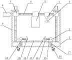
Fig. 1 is a schematic front sectional view of a polishing device for producing and processing a switch cabinet shell.
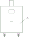
Fig. 2 is a schematic side view of a polishing device for producing and processing a switch cabinet shell.
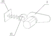
Fig. 3 is a schematic perspective view of a cam transmission mechanism in a polishing device for producing and processing a switch cabinet shell.
Wherein: the polishing device comprises a base 1, a cam 2, a dust hood 3, a telescopic rod 4, a polishing component 5, a screw 6, a nut seat 7, a motor 8, a screw support 9, a motor seat 10, a push rod 11, a workbench 12, a clamping plate 13, a guide plate 14, a pulley device 15, a universal wheel 16 and a compression spring 17.
Detailed Description
It should be noted that the embodiments and features of the embodiments may be combined with each other without conflict.
In the description of the present invention, it is to be understood that the terms "center", "longitudinal", "lateral", "up", "down", "front", "back", "left", "right", "vertical", "horizontal", "top", "bottom", "inner", "outer", and the like, indicate orientations or positional relationships based on those shown in the drawings, and are used only for convenience in describing the present invention and for simplicity in description, and do not indicate or imply that the referenced devices or elements must have a particular orientation, be constructed and operated in a particular orientation, and thus, are not to be construed as limiting the present invention. Furthermore, the terms "first", "second", etc. are used for descriptive purposes only and are not to be construed as indicating or implying relative importance or implicitly indicating the number of technical features indicated. Thus, a feature defined as "first," "second," etc. may explicitly or implicitly include one or more of that feature. In the description of the present invention, "a plurality" means two or more unless otherwise specified.
In the description of the present invention, it should be noted that, unless otherwise explicitly specified or limited, the terms "mounted," "connected," and "connected" are to be construed broadly, e.g., as meaning either a fixed connection, a removable connection, or an integral connection; can be mechanically or electrically connected; they may be connected directly or indirectly through intervening media, or they may be interconnected between two elements. The specific meaning of the above terms in the present invention can be understood by those of ordinary skill in the art through specific situations.
The present invention will be described in detail below with reference to the embodiments with reference to the attached drawings.
Example one
Referring to fig. 1-3, a polishing device for producing and processing a switch cabinet shell comprises a base 1, a polishing assembly 5, a motor and a motor base 10; the base 1 is a hollow structure with through holes on the left side and the right side of the top; the edge of the left side and the edge of the right side of the top of the base 1 are symmetrically and fixedly provided with L-shaped screw rod supports 9 with upper and lower through holes on the side walls, a screw rod is rotatably arranged between the screw rod supports 9 and the top of the base 1, the screw rod is rotatably connected with a nut seat, and the top of the screw rod extends out of the screw rod supports 9 and is rotatably connected with a motor; a screw 6 in the left and right directions is rotatably connected between the left and right nut seats, two nut seats 7 are rotatably mounted on the screw 6 from left to right, and the bottoms of the nut seats 7 on the left and right sides are respectively and fixedly provided with a polishing assembly 5 and a telescopic rod 4; a workbench 12 is fixedly installed in the middle of the top of the base 1, motor bases 10 are symmetrically and fixedly installed on the left side and the right side of the workbench 12 on the top of the base 1, and guide plates 14 are fixedly installed between the workbench 12 and the motor bases 10; a motor is fixedly installed at the top of the motor base 10, the motor is rotatably connected with a cam 2 through a rotating shaft, a pulley device 15 which is always in contact with the side face of the cam 2 is installed on the right side of the cam 2, a push rod 11 extending out of a guide plate 14 is fixedly installed on the right side of the pulley device 15, a clamping plate 13 is fixedly connected with the free end of the push rod 11, and a compression spring is installed between the pulley device 15 and the guide plate 14; the motor on the motor base 10 is started, the motor drives the cam 2 to perform circular motion, the circular motion of the cam 2 further drives the pulley device 15 to perform reciprocating motion in the left-right direction, the reciprocating motion in the left-right direction of the pulley device 15 further drives the push rod to perform reciprocating motion in the left-right direction, and therefore the push rod can drive the clamping plates 13 to be close to or far away from each other, and therefore fixing and releasing actions on the switch cabinet shell are completed.
Example two
On the basis of the first embodiment, in order to optimize the performance of the device, a plurality of compression springs 17 are arranged inside the base 1, and the arrangement of the compression springs 17 can improve the stability of the device; a plurality of universal wheels 16 are fixedly arranged at the bottom of the base 1, and the universal wheels 16 are arranged to facilitate the movement of the device; the bottom fixed mounting of telescopic link 4 has suction hood 3, the setting of suction hood 3 can be effectual absorbs the dust that produces among the polishing process.
The working principle of the utility model is as follows: when the polishing device is used, the position of the polishing component 5 is adjusted according to the positions of the workbench 12 and the switch cabinet shell, the motor at the top of the screw rod bracket 9 is started, and the motor drives the screw rod to rotate, so that the upper position and the lower position of the polishing component 5 can be adjusted; then starting a motor 8 on the side surface of the screw rod bracket 9, wherein the motor 8 on the side surface can adjust the left and right direction positions of the polishing component 5; the motor on the motor base 10 is started, the motor drives the cam 2 to perform circular motion, the circular motion of the cam 2 further drives the pulley device 15 to perform reciprocating motion in the left-right direction, the reciprocating motion in the left-right direction of the pulley device 15 further drives the push rod to perform reciprocating motion in the left-right direction, and therefore the push rod can drive the clamping plates 13 to be close to or far away from each other, and therefore fixing and releasing actions on the switch cabinet shell are completed.
Although the preferred embodiments of the present patent have been described in detail, the present patent is not limited to the above embodiments, and various changes can be made without departing from the spirit of the present patent within the knowledge of those skilled in the art.