CN210256661U - Evaporate and press aerated concrete block forming device - Google Patents
Evaporate and press aerated concrete block forming device Download PDFInfo
- Publication number
- CN210256661U CN210256661U CN201920740967.1U CN201920740967U CN210256661U CN 210256661 U CN210256661 U CN 210256661U CN 201920740967 U CN201920740967 U CN 201920740967U CN 210256661 U CN210256661 U CN 210256661U
- Authority
- CN
- China
- Prior art keywords
- fixedly connected
- aerated concrete
- concrete block
- cutting
- forming device
- Prior art date
- Legal status (The legal status is an assumption and is not a legal conclusion. Google has not performed a legal analysis and makes no representation as to the accuracy of the status listed.)
- Expired - Fee Related
Links
Images
Abstract
The utility model discloses an evaporate and press aerated concrete block forming device, including the cutting bed, the equal fixedly connected with waste tank in both sides of cutting bed, waste tank's top fixedly connected with building block cutting machine. The utility model discloses a set up the cutting bed, the dirty silo, the block cutting machine, the dead lever, the transmission case, including a motor, an end cap, a controller, and a cover plate, the pivot, perpendicular slide bar, the transmission piece, the sliding sleeve, the slide bar, the connecting rod, electric telescopic handle, the brush, spacing spout, the mount, the cooperation of logical groove and supporting leg is used, solved in the production process who evaporates pressure aerated concrete block, need to evaporate and press aerated concrete block cutting shaping, a large amount of dust granule and piece can appear in cutting process, remaining dust granule and piece can evaporate the problem that the cutting of pressing aerated concrete block led to the fact the influence to next batch, made things convenient for to evaporate the machine-shaping who evaporates pressure aerated concrete block, the practicality that evaporates pressure aerated concrete block forming device.
Description
Technical Field
The utility model relates to a building materials processing technology field specifically is an evaporate and press aerated concrete block forming device.
Background
The autoclaved aerated concrete block is a porous concrete product prepared by using fly ash, lime, cement, gypsum, slag and the like as main raw materials, adding a proper amount of a gas former, a regulator and a bubble stabilizer, and carrying out the processes of batching, stirring, pouring, standing, cutting, high-pressure steam curing and the like.
In the production process of the autoclaved aerated concrete block, the autoclaved aerated concrete block needs to be cut and formed, a large amount of dust particles and scraps can appear in the cutting process, the residual dust particles and scraps can influence the cutting of the next batch of autoclaved aerated concrete block, inconvenience is brought to the processing and forming of the autoclaved aerated concrete block, and the practicability of the autoclaved aerated concrete block forming device is reduced.
SUMMERY OF THE UTILITY MODEL
Technical problem to be solved
Not enough to prior art, the utility model provides an evaporate aerated concrete block forming device that presses possesses the advantage of high-efficient dust removal, has solved current evaporate and press aerated concrete block forming device and do not possess the problem of high-efficient dust removal.
(II) technical scheme
In order to realize the above-mentioned purpose that possesses high-efficient dust removal, the utility model provides a following technical scheme: the autoclaved aerated concrete block forming device comprises a cutting table, wherein both sides of the cutting table are fixedly connected with a waste material groove, the top of the waste material groove is fixedly connected with a block cutting machine, the top of the block cutting machine is fixedly connected with a fixed rod, the top of the fixed rod is fixedly connected with a transmission case, the inner cavity of the transmission case is provided with a motor, the output end of the motor is rotatably connected with a rotating shaft, the other end of the rotating shaft is fixedly connected with a vertical sliding rod, the front side of the vertical sliding rod is movably connected with a transmission block, the bottom of the transmission block is fixedly connected with a sliding sleeve, the inner cavity of the sliding sleeve is slidably connected with a sliding rod, both sides of the sliding rod are respectively fixedly connected with both sides of the inner cavity of the transmission case, the bottom of the sliding sleeve is fixedly connected with, the bottom of the electric telescopic rod is fixedly connected with a hairbrush.
Preferably, the surface of the transmission block is provided with a limiting sliding groove matched with the vertical sliding rod for use, the front side of the vertical sliding rod penetrates through the front side of the limiting sliding groove and is fixedly connected with a stop block, and the surface of the front side of the vertical sliding rod is connected with the inner wall of the limiting sliding groove in a sliding mode.
Preferably, both sides of the motor are fixedly connected with a fixing frame, and the top of the fixing frame is fixedly connected with the top of the inner cavity of the transmission case.
Preferably, the bottom of transmission case is seted up and is made things convenient for the gliding logical groove of connecting rod, the surface of connecting rod and the inner wall sliding connection who leads to the groove.
Preferably, the bottom of the cutting table is fixedly connected with a supporting leg, and the bottom of the supporting leg is fixedly connected with an anti-slip mat.
(III) advantageous effects
Compared with the prior art, the utility model provides an evaporate and press aerated concrete block forming device possesses following beneficial effect:
1. the utility model discloses a set up the cutting bed, the dirty silo, the block cutting machine, the dead lever, the transmission case, including a motor, an end cap, a controller, and a cover plate, the pivot, perpendicular slide bar, the transmission piece, the sliding sleeve, the slide bar, the connecting rod, electric telescopic handle, the brush, spacing spout, the mount, the cooperation of logical groove and supporting leg is used, solved in the production process who evaporates pressure aerated concrete block, need to evaporate and press aerated concrete block cutting shaping, a large amount of dust granule and piece can appear in cutting process, remaining dust granule and piece can evaporate the problem that the cutting of pressing aerated concrete block led to the fact the influence to next batch, made things convenient for to evaporate the machine-shaping who evaporates pressure aerated concrete block, the practicality that evaporates pressure aerated concrete block forming device.
2. The utility model discloses a set up logical groove, made things convenient for the slip of connecting rod in the transmission bottom of the case portion, reduced the frictional force between connecting rod and the transmission, prolonged the life of part, fix the motor through setting up the mount to prevent that the phenomenon of skew from appearing in the motor when the function, through setting up spacing spout, made things convenient for the slip of perpendicular slide bar in the transmission piece, reduced the frictional force between perpendicular slide bar and the transmission piece, prolonged the life of part.
Drawings
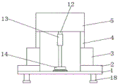
FIG. 1 is a schematic structural view of the present invention;
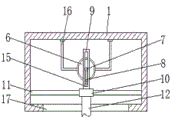
FIG. 2 is a cross-sectional view of the transmission case of the present invention;
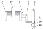
fig. 3 is a left side view of the motor of the present invention.
In the figure: 1 cutting bed, 2 waste material troughs, 3 building block cutting machines, 4 fixed rods, 5 transmission boxes, 6 motors, 7 rotating shafts, 8 vertical sliding rods, 9 transmission blocks, 10 sliding sleeves, 11 sliding rods, 12 connecting rods, 13 electric telescopic rods, 14 brushes, 15 limiting sliding chutes, 16 fixed frames, 17 through grooves and 18 supporting legs.
Detailed Description
The technical solutions in the embodiments of the present invention will be described clearly and completely with reference to the accompanying drawings in the embodiments of the present invention, and it is obvious that the described embodiments are only some embodiments of the present invention, not all embodiments. Based on the embodiments in the present invention, all other embodiments obtained by a person skilled in the art without creative work belong to the protection scope of the present invention.
Referring to fig. 1-3, an autoclaved aerated concrete block forming device comprises a cutting table 1, wherein the bottom of the cutting table 1 is fixedly connected with a supporting leg 18, the bottom of the supporting leg 18 is fixedly connected with an anti-slip mat, both sides of the cutting table 1 are fixedly connected with a waste chute 2, the top of the waste chute 2 is fixedly connected with a block cutting machine 3, the top of the block cutting machine 3 is fixedly connected with a fixed rod 4, the top of the fixed rod 4 is fixedly connected with a transmission case 5, the inner cavity of the transmission case 5 is provided with a motor 6, both sides of the motor 6 are fixedly connected with a fixed frame 16, the top of the fixed frame 16 is fixedly connected with the top of the inner cavity of the transmission case 5, the motor 6 is fixed by arranging the fixed frame 16, thereby preventing the motor 6 from deviating during operation, the output end of the motor 6 is rotatably connected, the front side of the vertical sliding rod 8 is movably connected with a transmission block 9, the surface of the transmission block 9 is provided with a limit sliding chute 15 matched with the vertical sliding rod 8 for use, the front side of the vertical sliding rod 8 penetrates to the front side of the limit sliding chute 15 and is fixedly connected with a stop block, the surface of the front side of the vertical sliding rod 8 is in sliding connection with the inner wall of the limit sliding chute 15, through the arrangement of the limit sliding chute 15, the sliding of the vertical sliding rod 8 in the transmission block 9 is facilitated, the friction force between the vertical sliding rod 8 and the transmission block 9 is reduced, the service life of a part is prolonged, the bottom of the transmission block 9 is fixedly connected with a sliding sleeve 10, the inner cavity of the sliding sleeve 10 is in sliding connection with a sliding rod 11, two sides of the sliding rod 11 are respectively and fixedly connected with two sides of the inner cavity of the transmission case 5, the bottom of the sliding sleeve 10 is fixedly connected with a connecting rod 12, the bottom of, the surface of connecting rod 12 and the inner wall sliding connection who leads to groove 17, the utility model discloses a setting up and leading to groove 17, made things convenient for the slip of connecting rod 12 in transmission case 5 bottom, reduced the frictional force between connecting rod 12 and the transmission case 5, prolonged the life of part, electric telescopic handle 13's bottom fixedly connected with brush 14.
When in use, after the block cutting machine 3 finishes cutting the blocks, a user starts the electric telescopic rod 13, the electric telescopic rod 13 extends to the surface of the cutting table 1, meanwhile, the electric telescopic rod 13 drives the brush 14 to move, when the bottom of the brush 14 contacts the surface of the cutting table 1, the electric telescopic rod 13 is closed, meanwhile, the motor 6 is started, the output end of the motor 6 drives the rotating shaft 7 to rotate, the rotating shaft 7 drives the vertical sliding rod 8 to rotate, the vertical sliding rod 8 drives the transmission block 9 to reciprocate left and right, the transmission block 9 drives the sliding sleeve 10 to slide on the surface of the sliding rod 11, meanwhile, the sliding sleeve 10 drives the electric telescopic rod 13 to reciprocate left and right through the connecting rod 12, the movement of the electric telescopic rod 13 drives the brush 14 to slide on the surface of the cutting table 1, the sliding of the brush 14 cleans dust particles and debris on the surface of the cutting table 1, and the cleaned dust particles and debris are discharged through the waste chute 2.
In conclusion, this evaporate and press aerated concrete block forming device, through setting up cutting bed 1, waste chute 2, building block cutting machine 3, dead lever 4, transmission case 5, motor 6, pivot 7, perpendicular slide bar 8, driving block 9, sliding sleeve 10, slide bar 11, connecting rod 12, electric telescopic handle 13, brush 14, spacing spout 15, mount 16, lead to the cooperation of groove 17 and supporting leg 18 and use, solved current evaporate and press aerated concrete block forming device and do not possess the problem of high-efficient dust removal.
Although embodiments of the present invention have been shown and described, it will be appreciated by those skilled in the art that changes, modifications, substitutions and alterations can be made in these embodiments without departing from the principles and spirit of the invention, the scope of which is defined in the appended claims and their equivalents.
Claims (5)
1. The utility model provides an evaporate and press aerated concrete block forming device, includes cutting bed (1), its characterized in that: the cutting machine is characterized in that waste chutes (2) are fixedly connected to two sides of the cutting table (1), block cutting machines (3) are fixedly connected to the tops of the waste chutes (2), fixing rods (4) are fixedly connected to the tops of the block cutting machines (3), transmission boxes (5) are fixedly connected to the tops of the fixing rods (4), motors (6) are arranged in inner cavities of the transmission boxes (5), output ends of the motors (6) are rotatably connected with rotating shafts (7), vertical sliding rods (8) are fixedly connected to the other ends of the rotating shafts (7), transmission blocks (9) are movably connected to the front sides of the vertical sliding rods (8), sliding sleeves (10) are fixedly connected to the bottoms of the transmission blocks (9), sliding rods (11) are slidably connected to inner cavities of the sliding sleeves (10), and two sides of the sliding rods (11) are fixedly connected to two sides of an inner cavity of the, the bottom fixedly connected with connecting rod (12) of sliding sleeve (10), the bottom of connecting rod (12) runs through to the bottom of transmission case (5) and fixedly connected with electric telescopic handle (13), the bottom fixedly connected with brush (14) of electric telescopic handle (13).
2. The autoclaved aerated concrete block forming device according to claim 1, characterized in that: the surface of transmission piece (9) is seted up with perpendicular slide bar (8) cooperation use spacing spout (15), the front side of perpendicular slide bar (8) runs through to the front side and the fixedly connected with dog of spacing spout (15), the surface of perpendicular slide bar (8) front side and the inner wall sliding connection of spacing spout (15).
3. The autoclaved aerated concrete block forming device according to claim 1, characterized in that: the motor is characterized in that fixing frames (16) are fixedly connected to the two sides of the motor (6), and the tops of the fixing frames (16) are fixedly connected with the top of the inner cavity of the transmission case (5).
4. The autoclaved aerated concrete block forming device according to claim 1, characterized in that: the bottom of transmission case (5) is seted up and is made things convenient for gliding logical groove (17) of connecting rod (12), the surface of connecting rod (12) and the inner wall sliding connection who leads to groove (17).
5. The autoclaved aerated concrete block forming device according to claim 1, characterized in that: the bottom of the cutting table (1) is fixedly connected with supporting legs (18), and the bottom of the supporting legs (18) is fixedly connected with an anti-slip mat.
Priority Applications (1)
| Application Number | Priority Date | Filing Date | Title |
|---|---|---|---|
| CN201920740967.1U CN210256661U (en) | 2019-05-22 | 2019-05-22 | Evaporate and press aerated concrete block forming device |
Applications Claiming Priority (1)
| Application Number | Priority Date | Filing Date | Title |
|---|---|---|---|
| CN201920740967.1U CN210256661U (en) | 2019-05-22 | 2019-05-22 | Evaporate and press aerated concrete block forming device |
Publications (1)
| Publication Number | Publication Date |
|---|---|
| CN210256661U true CN210256661U (en) | 2020-04-07 |
Family
ID=70026089
Family Applications (1)
| Application Number | Title | Priority Date | Filing Date |
|---|---|---|---|
| CN201920740967.1U Expired - Fee Related CN210256661U (en) | 2019-05-22 | 2019-05-22 | Evaporate and press aerated concrete block forming device |
Country Status (1)
| Country | Link |
|---|---|
| CN (1) | CN210256661U (en) |
Cited By (1)
| Publication number | Priority date | Publication date | Assignee | Title |
|---|---|---|---|---|
| CN112589961A (en) * | 2020-11-11 | 2021-04-02 | 福建同利建材科技有限公司 | Forming device for manufacturing concrete building blocks |
-
2019
- 2019-05-22 CN CN201920740967.1U patent/CN210256661U/en not_active Expired - Fee Related
Cited By (1)
| Publication number | Priority date | Publication date | Assignee | Title |
|---|---|---|---|---|
| CN112589961A (en) * | 2020-11-11 | 2021-04-02 | 福建同利建材科技有限公司 | Forming device for manufacturing concrete building blocks |
Similar Documents
| Publication | Publication Date | Title |
|---|---|---|
| CN205651699U (en) | Saw -dust compaction forming device | |
| CN211027480U (en) | Wallpaper trimming waste paper cleaning device | |
| CN210256661U (en) | Evaporate and press aerated concrete block forming device | |
| CN112109180B (en) | Hollow gray brick impression manufacturing device for brickyard | |
| CN206201230U (en) | A kind of ceramic cutter sweep of easy cleaning blanking | |
| CN210571640U (en) | Molding and jolt ramming table for mortar test body | |
| CN112621432A (en) | Wood grinding device for furniture processing | |
| CN207273479U (en) | Jolly | |
| CN210477424U (en) | Dustproof ceramic tile cutting equipment | |
| CN215038589U (en) | Steam pressure building block production is with framed fat liquoring equipment | |
| CN212553081U (en) | Corner grinding device for ceramic manufacture that multi-angle was adjusted | |
| CN215312699U (en) | Evaporate and press cinder grinder for aerated concrete block processing | |
| CN211305767U (en) | Equal-height polishing equipment for bottoms of bathtubs or wash basins | |
| CN211566190U (en) | Cutting saw for producing straw composite board furniture | |
| CN214979222U (en) | Machining table convenient to clean for aluminum product machining | |
| CN215703021U (en) | Automatic stone cutting machine of material loading | |
| CN213732461U (en) | Building block makes with pouring device | |
| CN219153092U (en) | EPE pearl cotton production is with punching press exhaust device | |
| CN220575466U (en) | Glass production processing edging machine | |
| CN212946955U (en) | Building materials burr grinding device | |
| CN210256663U (en) | Concrete dicing device with excess material recovery bin | |
| CN215319751U (en) | Concrete removing and cutting mechanism | |
| CN211492157U (en) | Press for producing refractory bricks | |
| CN217017610U (en) | Waste cleaning device for paper pulp hot press | |
| CN108145804A (en) | The cutting mechanism of furniture decoration wood skin |
Legal Events
| Date | Code | Title | Description |
|---|---|---|---|
| GR01 | Patent grant | ||
| GR01 | Patent grant | ||
| CF01 | Termination of patent right due to non-payment of annual fee | ||
| CF01 | Termination of patent right due to non-payment of annual fee |
Granted publication date: 20200407 Termination date: 20210522 |