CN210231470U - Hydraulic lifting sliding steel moving device - Google Patents
Hydraulic lifting sliding steel moving device Download PDFInfo
- Publication number
- CN210231470U CN210231470U CN201920371515.0U CN201920371515U CN210231470U CN 210231470 U CN210231470 U CN 210231470U CN 201920371515 U CN201920371515 U CN 201920371515U CN 210231470 U CN210231470 U CN 210231470U
- Authority
- CN
- China
- Prior art keywords
- billet
- steel
- unloading
- sliding
- roller way
- Prior art date
- Legal status (The legal status is an assumption and is not a legal conclusion. Google has not performed a legal analysis and makes no representation as to the accuracy of the status listed.)
- Active
Links
Images


Abstract
The utility model relates to a hydraulic pressure promotes and slides steel shifting device belongs to metallurgical industry steel mill continuous casting mechanical equipment technical field. The technical scheme is as follows: the billet unloading roller way is composed of a plurality of billet unloading rollers (1) which are arranged in parallel, a billet cache frame (6) is arranged on one side of the billet unloading roller way, a plurality of slide rails (2) which are arranged in parallel with the billet unloading rollers (1) are arranged between the billet unloading rollers (1), one ends of the slide rails (2) are fixed on longitudinal beams (3), hydraulic cylinders (5) are in driving connection with the longitudinal beams (3), the other ends of the slide rails (2) are fixed on rotating shafts (4), the rotating shafts (4) are arranged on one sides of the billet unloading roller way, which are provided with the billet cache frame (6), and the upper surfaces of the slide rails (2) are lower than the upper surfaces of the billet unloading rollers (1). The utility model has the advantages that: the steel billet produced by the continuous casting machine can be smoothly transferred to the steel billet cache frame, and the steel billet is prevented from being damaged by a billet unloading roller way and other steel moving equipment in the billet unloading process.
Description
Technical Field
The utility model relates to a hydraulic pressure promotes and slides steel shifting device belongs to metallurgical industry steel mill continuous casting mechanical equipment technical field.
Background
The transverse steel moving trolley (machine) is important equipment on a continuous casting machine in a steel plant, and has the functions of: and (3) moving the steel billets produced by the continuous casting machine to a temporary billet storage rack and a cooling bed through a billet unloading roller way to finish the change of the casting billets in the conveying channel and the direction.
At present, the most common steel moving mode of the billet removing roller bed is that the steel billet is moved to the temporary storage rack and the cooling machine from the billet removing roller bed by adopting a transverse steel moving handle. The transverse steel moving vehicle adopts an elevated rail, the vehicle body is arranged on the elevated rail, and a motor, a speed reducer and a pusher dog are arranged on the vehicle body. Lean on motor, speed reducer directly to stir the casting blank of unloading on the base roll table and remove on keeping in frame and the cold bed, still install the slide rail in one side of unloading the base roll table, the casting blank is being promoted the in-process by the lateral shifting car, is being unloaded the bearing frame of base roll table easily, unload base roll table tip roller and block along the hookup department with the slide rail, causes the damage to motor, the speed reducer of unloading base roll table, slide rail even horizontal steel car.
SUMMERY OF THE UTILITY MODEL
The utility model aims at providing a hydraulic pressure promotes and slides and move steel device can be with smooth the transferring to steel billet buffer memory frame of the steel billet that the conticaster was produced, avoids unloading the base roll table and other move steel equipment and receive the damage, solves the problem that exists among the background art.
The technical scheme of the utility model is that:
a hydraulic lifting sliding steel moving device comprises a billet unloading roller way, sliding rails, longitudinal beams, a rotating shaft, a hydraulic cylinder and a billet cache frame, wherein the billet unloading roller way is composed of a plurality of billet unloading rollers which are arranged in parallel, the billet cache frame is arranged on one side of the billet unloading roller way, a plurality of sliding rails which are arranged in parallel with the billet unloading rollers are arranged between the billet unloading rollers, one ends of the sliding rails are fixed on the longitudinal beams, the hydraulic cylinder is in driving connection with the longitudinal beams, the other ends of the sliding rails are fixed on the rotating shaft, the rotating shaft is arranged on one side, provided with the billet cache frame, of the billet unloading roller way, and the upper surfaces of the sliding rails are lower.
The steel billet buffer storage frame comprises a plurality of sliding plates and sliding plate supporting seats which are arranged in parallel with the sliding rails, and two ends of the plurality of sliding plates are respectively fixed on the sliding plate supporting seats.
The upper surface of the sliding plate in the billet cache frame and the upper surface of the billet unloading roller are on the same horizontal plane.
The rotating shaft is fixed on the rotating shaft supporting seat through a bearing seat, and the rotating shaft is perpendicular to the sliding rail.
And a blank unloading roller in the blank unloading roller way is connected with a motor through a speed reducer.
The longitudinal beam is perpendicular to the sliding rail, and the hydraulic cylinders are arranged at two ends of the longitudinal beam.
Adopt the utility model discloses, after the steel billet that the conticaster was produced got into the ejection roller way, pneumatic cylinder control piston rod stretched out, and the drive longeron drives the slide rail and upwards lifts around the rotation axis, lifts the steel billet on the ejection roller way simultaneously and is lifted by the slide rail to on the steel billet buffer memory frame slides under the action of gravity, after the steel billet slides and targets in place, the piston rod of pneumatic cylinder withdraws, and the drive longeron drives the slide rail and rotates downwards around the rotation axis, makes the slide rail get back to initial position, accomplishes the sliding steel that moves of steel billet.
The utility model has the advantages that: on can transferring the smooth steel billet that conticaster produced to steel billet buffer memory frame, avoided the steel billet to unload the base roll table and other steel equipment that move and cause the damage at the base in-process of unloading, simple structure, compactness, area is little, and the fault rate is little, is particularly useful for multithread conticaster unloads the base process of unloading of base roll table.
Drawings
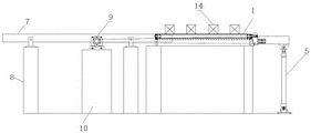
Fig. 1 is a top view of the present invention;
FIG. 2 is a view from A-A of the present invention;
FIG. 3 is a schematic view of the working state of the present invention;
in the figure: the steel billet unloading device comprises a billet unloading roller 1, a slide rail 2, a longitudinal beam 3, a rotating shaft 4, a hydraulic cylinder 5, a steel billet cache frame 6, a slide plate 7, a slide plate supporting seat 8, a bearing seat 9, a billet unloading bearing seat 11, a rotating shaft supporting seat 10, a speed reducer 12, a motor 13 and a steel billet 14.
Detailed Description
The invention will be further explained by way of example with reference to the accompanying drawings.
Referring to the attached drawings 1, 2 and 3, the hydraulic lifting sliding steel moving device comprises a billet unloading roller way, a slide rail 2, a longitudinal beam 3, a rotating shaft 4, a hydraulic cylinder 5 and a billet cache frame 6, wherein the billet unloading roller way is composed of a plurality of billet unloading rollers 1 which are arranged in parallel, the billet cache frame 6 is arranged on one side of the billet unloading roller way, the slide rails 2 which are arranged in parallel with the billet unloading rollers 1 are arranged between the billet unloading rollers 1, one ends of the slide rails 2 are fixed on the longitudinal beam 3, the hydraulic cylinder 5 is in driving connection with the longitudinal beam 3, the other ends of the slide rails 2 are fixed on the rotating shaft 4, the rotating shaft 4 is arranged on one side of the billet unloading roller way, which is provided with the billet cache frame 6, and the upper surfaces of the slide rails.
In this embodiment: referring to the attached drawings 1, 2 and 3, the continuous casting machine is a four-machine four-flow continuous casting machine, a billet-removing roller bed of the four-machine four-flow continuous casting machine is composed of six identical billet-removing rollers 1, and each billet-removing roller 1 is respectively driven by a speed reducer 12 and a motor 13.
Set up and unload three slide rail 2 of blank roller 1 parallel arrangement between unloading blank roller 1, the one end of three slide rail 2 is fixed respectively on a longeron 3, longeron 3 is driven by two pneumatic cylinders 5, the other end of three slide rail 2 is installed on a rotation axis 4, rotation axis 4 is fixed on rotation axis supporting seat 10 through four bearing blocks 9, longeron 3 and rotation axis 4 all arrange with slide rail 2 is perpendicular, the upper surface of three slide rail 2 is less than the upper surface of unloading blank roller 4.
Billet buffer memory frame 6 sets up in one side of rotation axis 4, and billet buffer memory frame 6 contains four slides 7 and slide supporting seat 8 with slide rail 2 parallel arrangement, and the both ends of four slides 7 are fixed respectively on slide supporting seat 8, and the upper surface of four slides 7 and the upper surface of unloading the base roll table are on the coplanar.
The working process of the utility model is as follows:
after four steel billets 14 of four quick-witted four-strand continuous casting machine production got into the blank-removing roll table, pneumatic cylinder 5 was stretched out by hydraulic system control piston rod, drive longeron 3 drove three slide rails 2 and upwards lift around rotation axis 4, four steel billets 14 on the blank-removing roll table are also lifted by three slide rails 2 simultaneously, and slide down on billet buffer frame 6 under the action of gravity, four steel billets 14 slide the back that targets in place, hydraulic cylinder 5's piston rod is withdrawed under the hydraulic system effect, drive longeron 3 drives three slide rails 2 and downwards rotates around rotation axis 4, when the piston rod of pneumatic cylinder 5 is retrieved and targets in place the back, three slide rails 2's upper surface is less than the upper surface of blank-removing roller 1, get back to the initial position, make the next steel preparation that moves.
The billet cache frame 6 is used for temporarily storing billets 14, and the billets 14 on the billet cache frame 6 are moved to a cooling bed by a cooling bed steel-pulling mechanism for cooling and straightening.
Claims (6)
1. The utility model provides a hydraulic pressure promotes and slides steel device which characterized in that: the steel billet unloading device comprises a billet unloading roller way, a sliding rail (2), a longitudinal beam (3), a rotating shaft (4), a hydraulic cylinder (5) and a billet cache frame (6), wherein the billet unloading roller way is composed of a plurality of billet unloading rollers (1) which are arranged in parallel, the billet cache frame (6) is arranged on one side of the billet unloading roller way, the plurality of sliding rails (2) which are arranged in parallel with the billet unloading rollers (1) are arranged between the billet unloading rollers (1), one ends of the sliding rails (2) are fixed on the longitudinal beam (3), the hydraulic cylinder (5) is in driving connection with the longitudinal beam (3), the other ends of the sliding rails (2) are fixed on the rotating shaft (4), the rotating shaft (4) is arranged on one side of the billet unloading roller way, which is provided with the billet cache frame (6), and the upper surface of the sliding rails (.
2. The hydraulic lifting sliding steel-moving device according to claim 1, characterized in that: the steel billet caching frame (6) comprises a plurality of sliding plates (7) and sliding plate supporting seats (8) which are arranged in parallel with the sliding rails (2), and two ends of the sliding plates (7) are fixed on the sliding plate supporting seats (8) respectively.
3. The hydraulic lifting sliding steel-moving device according to claim 2, characterized in that: the upper surface of a sliding plate (7) in the billet cache frame (6) and the upper surface of the blank discharging roller (1) are on the same horizontal plane.
4. The hydraulic lifting sliding steel-moving device according to claim 1, characterized in that: the rotating shaft (4) is fixed on the rotating shaft supporting seat (10) through a bearing seat (9), and the rotating shaft (4) is perpendicular to the sliding rail (2).
5. The hydraulic lifting sliding steel-moving device according to claim 1, characterized in that: and a blank discharging roller (1) in the blank discharging roller way is connected with a motor (13) through a speed reducer (12).
6. The hydraulic lifting sliding steel-moving device according to claim 1, characterized in that: the longitudinal beam (3) is perpendicular to the sliding rail (2), and the hydraulic cylinders (5) are arranged at two ends of the longitudinal beam (3).
Priority Applications (1)
| Application Number | Priority Date | Filing Date | Title |
|---|---|---|---|
| CN201920371515.0U CN210231470U (en) | 2019-03-22 | 2019-03-22 | Hydraulic lifting sliding steel moving device |
Applications Claiming Priority (1)
| Application Number | Priority Date | Filing Date | Title |
|---|---|---|---|
| CN201920371515.0U CN210231470U (en) | 2019-03-22 | 2019-03-22 | Hydraulic lifting sliding steel moving device |
Publications (1)
| Publication Number | Publication Date |
|---|---|
| CN210231470U true CN210231470U (en) | 2020-04-03 |
Family
ID=69962033
Family Applications (1)
| Application Number | Title | Priority Date | Filing Date |
|---|---|---|---|
| CN201920371515.0U Active CN210231470U (en) | 2019-03-22 | 2019-03-22 | Hydraulic lifting sliding steel moving device |
Country Status (1)
| Country | Link |
|---|---|
| CN (1) | CN210231470U (en) |
Cited By (1)
| Publication number | Priority date | Publication date | Assignee | Title |
|---|---|---|---|---|
| CN109877286A (en) * | 2019-03-22 | 2019-06-14 | 宣化钢铁集团有限责任公司 | A kind of sliding of hydraulic pressure lift moves steel device and moves steel method |
-
2019
- 2019-03-22 CN CN201920371515.0U patent/CN210231470U/en active Active
Cited By (1)
| Publication number | Priority date | Publication date | Assignee | Title |
|---|---|---|---|---|
| CN109877286A (en) * | 2019-03-22 | 2019-06-14 | 宣化钢铁集团有限责任公司 | A kind of sliding of hydraulic pressure lift moves steel device and moves steel method |
Similar Documents
| Publication | Publication Date | Title |
|---|---|---|
| CN209815290U (en) | Rotary type cold-rolled steel coil packaging system | |
| CN112141873A (en) | Wooden cabinet body transfer equipment | |
| CN109384041B (en) | Two-side overturning feeding manipulator | |
| CN212291502U (en) | Four-column type lifting die changing trolley | |
| CN210231470U (en) | Hydraulic lifting sliding steel moving device | |
| CN110668085A (en) | Material moving and conveying system | |
| CN214933379U (en) | High-speed wire coil conveying trolley | |
| CN210593954U (en) | Roller way propelling device | |
| CN112872214A (en) | Special automatic forming machine for lifting ring | |
| JPH0223241B2 (en) | ||
| CN215433173U (en) | Automatic burr polishing line for cast-forged pieces | |
| CN106181547B (en) | Feeding mechanical hand and ball blast shear loading and unloading automatic system | |
| CN212442581U (en) | Casting blank feeding device with automatic steel distribution function | |
| CN211225041U (en) | Double-station coiled material transfer device | |
| CN109877286A (en) | A kind of sliding of hydraulic pressure lift moves steel device and moves steel method | |
| CN210824474U (en) | Steel plate stacking device | |
| CN107892158B (en) | Loading and unloading machine for loading and unloading axles | |
| CN210937046U (en) | Off-line collecting device for stepping cooling bed of bloom continuous casting machine | |
| CN207580713U (en) | A kind of two-way delivery platform of section bar | |
| CN110861872A (en) | Double-station coiled material transfer device and method | |
| US4282048A (en) | Method for cooling hot-rolled shapes | |
| CN110733857A (en) | Rectangular frame reinforcing bar centre gripping conveyer | |
| US3698469A (en) | Dummy bar handling system | |
| CN109848220A (en) | The roll replacing options of four-high mill | |
| CN217616852U (en) | Electro-hydraulic combined type steel distributing device |
Legal Events
| Date | Code | Title | Description |
|---|---|---|---|
| GR01 | Patent grant | ||
| GR01 | Patent grant |