CN210206427U - Industrial waste gas treatment device - Google Patents
Industrial waste gas treatment device Download PDFInfo
- Publication number
- CN210206427U CN210206427U CN201921039475.6U CN201921039475U CN210206427U CN 210206427 U CN210206427 U CN 210206427U CN 201921039475 U CN201921039475 U CN 201921039475U CN 210206427 U CN210206427 U CN 210206427U
- Authority
- CN
- China
- Prior art keywords
- box
- dust removal
- waste gas
- treatment device
- industrial waste
- Prior art date
- Legal status (The legal status is an assumption and is not a legal conclusion. Google has not performed a legal analysis and makes no representation as to the accuracy of the status listed.)
- Expired - Fee Related
Links
Images


Abstract
The utility model relates to a waste gas treatment device, concretely relates to industrial waste gas treatment device. The air exhaust device comprises a filter box, a cooling box, a dust removal box, an ionization box and a gas washing box, wherein the filter box, the dust removal box, the ionization box and the gas washing box are arranged at intervals, the cooling box is fixedly arranged between the filter box and the dust removal box, an air exhaust fan is arranged between the dust removal box and the ionization box, the air exhaust fan is respectively communicated with the dust removal box and the ionization box, an exhaust pipe is arranged on one side of the ionization box, and the end of the exhaust pipe extends to the bottom end of the gas washing box. This industrial waste gas treatment device has that the treatment effect is good and not fragile characteristics, utilizes the cooler bin to reduce exhaust gas temperature, can prevent that waste gas from causing the damage to equipment, through carrying out the humidification to waste gas, the particulate matter in the high-speed rotatory dust removal pole of cooperation can the effective absorption waste gas, has solved the poor and easy problem of damaging of treatment effect that current exhaust gas treatment device exists, has satisfied industrial waste gas's processing needs.
Description
Technical Field
The utility model relates to a waste gas treatment device, concretely relates to industrial waste gas treatment device.
Background
In the industrial production process, a large amount of industrial waste gas is generated by fuel combustion and chemical process treatment, and the industrial waste gas contains a plurality of pollutants harmful to the environment and human bodies, so that the industrial waste gas needs to be purified, the content of the harmful substances in the waste gas is reduced to be below a safety standard, and then the waste gas can be discharged.
The traditional waste gas treatment device has poor treatment capacity on particulate matters in waste gas, and because the inhaled particulate matters can cause harm to the respiratory tract of a human body, the emission standards of industrial waste gas containing the particulate matters are strict in various places, so that the emission standards are difficult to reach by adopting the traditional waste gas treatment device; in addition, since the industrial waste gas has a complex composition and the combustion waste gas has a high temperature, the waste gas may damage the treatment device, resulting in a short life of the conventional waste gas treatment device, and therefore, a new industrial waste gas treatment device is required to solve the above-mentioned disadvantages.
Disclosure of Invention
The utility model aims to provide a: the industrial waste gas treatment device has good waste gas treatment effect and is not easy to damage, and the problems that the waste gas treatment effect is poor and the waste gas treatment device is easy to damage existing in the conventional waste gas treatment device are solved.
The technical scheme of the utility model is that:
the utility model provides an industrial waste gas treatment device, it comprises rose box, cooler bin, dust removal case, ionization case and gas washing case, its characterized in that: the filter box, the dust removal box, the ionization box and the gas washing box are arranged at intervals, the cooling box is fixedly arranged between the filter box and the dust removal box, the exhaust fan is arranged between the dust removal box and the ionization box and is respectively communicated with the dust removal box and the ionization box, the exhaust pipe is arranged on one side of the ionization box, and the end of the exhaust pipe extends to the bottom end of the gas washing box.
The filter box consists of a filter box body, a filter screen and a collecting box, wherein the filter screen is fixedly arranged in the filter box body in an inclined manner, and the collecting box is arranged on the filter box body below the filter screen.
The filter screen is composed of intercepting rods arranged at intervals.
The cooling box comprises a cooling box body and air pipes, the air pipes are uniformly distributed in the cooling box body in the radial direction, a water inlet pipe A is installed at the top end of the cooling box body, and a water outlet pipe A is installed at the bottom end of the cooling box body.
The dust removal case constitute by dust removal box, humidifier, motor and dust removal subassembly, the humidifier is equipped with admittedly to one end in the dust removal box, and the motor is equipped with admittedly to the other end in the dust removal box, the interval is equipped with the dust removal subassembly admittedly on the output shaft of motor.
The inner chamber of the dust removal box body is a reducing chamber, one end of the inner chamber of the dust removal box body is a rectangular chamber, a water inlet pipe B is arranged at the top end of the rectangular chamber of the dust removal box body, the other end of the inner chamber of the dust removal box body is a circular chamber, and a water outlet pipe B is arranged at the bottom end of the circular chamber of the dust removal box body.
The humidifier consists of a guide pipe and nozzles, and a plurality of nozzles are fixedly arranged on the guide pipe at intervals.
The dust removal component comprises mounting rings, guide plates and dust removal rods, the mounting rings are symmetrically arranged, a plurality of guide plates are radially and fixedly arranged on the circumference between the mounting rings, and a plurality of dust removal rods are radially and fixedly arranged on the motor output shaft between the mounting rings.
The exhaust pipe is internally provided with an adsorbent, and a bottom end port of the exhaust pipe is provided with a one-way valve.
The gas washing box comprises a gas washing box body and partition plates, a liquid inlet hole is formed in the top end of the gas washing box body, a discharge pipe is installed on one side of the gas washing box body, the partition plates are arranged in the gas washing box body in a staggered mode, and blow-down holes are formed in the bottom end of the gas washing box body between the partition plates at intervals.
The utility model has the advantages that:
this industrial waste gas treatment device has that the exhaust-gas treatment is effectual and not fragile characteristics, utilizes the cooler bin to reduce exhaust gas temperature, can prevent that waste gas from causing the damage to equipment, through carrying out the humidification to waste gas, the particulate matter in the high-speed rotatory dust removal pole of cooperation can the effective absorption waste gas, has solved the poor and easy problem of damaging of exhaust-gas treatment effect that current exhaust-gas treatment device exists, has satisfied industrial waste gas's processing needs.
Drawings
Fig. 1 is a schematic structural view of the present invention;
FIG. 2 is a schematic structural view of the filter net of the present invention;
FIG. 3 is a schematic cross-sectional view taken along the line A-A in FIG. 1;
fig. 4 is a schematic sectional view taken along the direction B-B in fig. 1.
In the figure: 1. the device comprises a filtering box body, 2, a filter screen, 3, a collecting box, 4, an intercepting rod, 5, a dust removing box body, 6, a motor, 7, a dust removing component, 8, a guide pipe, 9, a spray head, 10, a water inlet pipe B, 11, a water source, 12, a dust removing rod, 13, a water outlet pipe B, 14, a cooling box body, 15, an air pipe, 16, a water inlet pipe A, 17, a water outlet pipe A, 18, an exhaust fan, 19, an exhaust pipe, 20, an adsorbent, 21, a one-way valve, 22, a gas washing box body, 23, a mounting ring, 24, a guide plate, 25, a partition plate, 26, a liquid inlet hole, 27, a discharge pipe, 28, an.
Detailed Description
The industrial waste gas treatment device comprises a filter box, a cooling box, a dust removal box, an ionization box 28 and a gas washing box, wherein the filter box, the dust removal box, the ionization box 28 and the gas washing box are arranged at intervals, the filter box comprises a filter box body 1, a filter screen 2 and a collecting box 3, the filter screen 2 is fixedly arranged in the filter box body 1 in an inclined mode, the filter screen 2 comprises intercepting rods 4 arranged at intervals, the filter screen 2 is used for filtering large-volume impurities in waste gas, the intercepting rods 4 have a guiding effect on the impurities and can enable the impurities to move downwards along the intercepting rods 4, the collecting box 3 is arranged on the filter box body 1 below the filter screen 2, through holes are formed in the filter box body 1 corresponding to the collecting box 3 so that the impurities downwards enter the collecting box 3, the collecting box 3 is used for collecting large-volume impurities in the waste gas at regular intervals, and the collecting box 3 can be recycled after being detached and.
The dust removal box comprises a dust removal box body 5, a humidifier, a motor 6 and a dust removal assembly 7, wherein the inner cavity of the dust removal box body 5 is a reducing cavity, one end of the inner cavity of the dust removal box body 5 is a rectangular cavity, the humidifier is arranged at the top end in the rectangular cavity of the dust removal box body 5 and consists of a guide pipe 8 and nozzles 9, the nozzles 9 are fixedly arranged on the guide pipe 8 at intervals, the nozzles 9 are used for humidifying waste gas, a water inlet pipe B10 is arranged on the dust removal box body 5 above the guide pipe 8, the water inlet pipe B10 is communicated with the guide pipe 8, and the water inlet pipe B10 is connected with a water source 11 so;
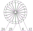
the other end of the inner cavity of the dust removal box body 5 is a circular cavity, a motor 6 is fixedly arranged in the circular cavity of the dust removal box body 5, dust removal assemblies 7 are fixedly arranged on an output shaft of the motor 6 at intervals, each dust removal assembly is composed of a mounting ring 23, a guide plate 24 and a dust removal rod 12, the mounting rings 23 are symmetrically arranged, the mounting rings 23 are fixedly connected with the dust removal box body 5, a plurality of guide plates 24 are fixedly arranged on the circumference between the mounting rings 23 in a radial mode, a plurality of dust removal rods 12 are fixedly arranged on the output shaft of the motor 6 between the mounting rings 23 in a radial mode, the dust removal rods 12 are used for adsorbing particles in humidified waste gas and throwing the particles onto the guide plates 24 by utilizing rotating centrifugal force, the diameter of each dust removal rod 12 is larger than the inner diameter of the mounting ring 23, but the dust removal rods 12 are not in contact with the guide plates 24, and the dust removal assemblies 7 rotate to a certain angle, so that the, the bottom end of the circular cavity of the dust removal box body 5 is provided with a water outlet pipe B13, and a water outlet pipe B13 is used for guiding out the particulate matter-containing wastewater in the dust removal box so as to collect and then uniformly purify the wastewater.
The cooling box is fixedly arranged between the filter box and the dust removal box and consists of a cooling box body 14 and an air pipe 15, the cooling box body 14 is closed, the air pipe 15 is uniformly distributed in the cooling box body 14 in the radial direction, two ends of the air pipe 15 are respectively communicated with the filter box and the dust removal box so as to cool waste gas and prevent high-temperature waste gas from damaging equipment in the device, a water inlet pipe A16 is arranged at the top end of the cooling box body 14, a water inlet pipe A16 is communicated with a water source 11 so as to provide cold water required by cooling, a water outlet pipe A17 is arranged at the bottom end of the cooling box body 14, the water outlet pipe A17 is used for discharging heated water, and the part of hot water can be added into a boiler.
An exhaust fan 18 is arranged between the dust removal box and the ionization box 28, the exhaust fan 18 is respectively communicated with the dust removal box and the ionization box 28 so as to enable the waste gas to continuously move forwards to enter the ionization box 28, electrodes are arranged in the ionization box 28 in an up-down shape and are connected with high voltage electricity, when the dust-containing gas passes through a high-voltage electrostatic field, the dust is electrically separated, and after dust particles and negative ions are combined to be charged negatively, the dust particles tend to be discharged from the surface of an anode and deposited, so that the waste gas is further subjected to dust removal. An exhaust pipe 19 is arranged on one side of the ionization box 28, an adsorbent 20 is arranged in the exhaust pipe 19, the adsorbent 20 is activated carbon, the adsorbent 20 is used for removing peculiar smell in waste gas, a check valve 21 is arranged at the bottom end port of the exhaust pipe 19, the check valve 21 is used for preventing water from flowing backwards into the exhaust pipe 19, and the end of the exhaust pipe 19 extends to the bottom end of the gas washing box (water washing box).
The gas washing tank is composed of a gas washing tank body 22 and a partition plate 25, a liquid inlet hole 26 is formed in the top end of the gas washing tank body 22, cleaning liquid is added into the gas washing tank through the liquid inlet hole 26, corresponding reactants are added into the cleaning liquid according to the composition of waste gas so that chemical reaction can be carried out to remove harmful gas in the waste gas, and the liquid inlet hole 26 is in a closed state when not used; the side of the scrubber box 22 is provided with a discharge pipe 27, the discharge pipe 27 is used for directly discharging the treated exhaust gas to the atmosphere, and the discharge pipe 27 also has the function of overflow so as to discharge excessive cleaning liquid; be the dislocation form in the gas washing box body 22 and be provided with baffle 25, baffle 25 is used for separating into tortuous runner with the gas washing box to increase gaseous stroke, reinforcing cleaning performance, the gas washing box body 22 bottom interval between the baffle 25 is provided with blowoff holes 29, when harmful gas in the waste gas and washing liquid reaction generate the sediment, can clear away the precipitate through regularly opening blowoff holes 29.
The working process of the waste gas treatment device is as follows: under the action of the exhaust fan 18, the industrial waste gas is sucked into the filter box, the waste gas entering the filter box moves forwards through the filter screen 2, and in the process, impurities with large volume in the waste gas are intercepted by the filter screen 2 and fall downwards into the collection box 3.
The waste gas after the impurity removal enters the air pipe 15 in the cooling box, the cooling water in the cooling box body 14 cools the waste gas in the air pipe 15, and meanwhile, the cooling water absorbs heat to become hot water which can be added into a boiler through the water outlet pipe A17 for use.
Waste gas after the cooling passes through trachea 15 and gets into the dust removal case, the humidifier carries out humidification to waste gas, waste gas after the humidification continues to move forward, because motor 6 drives dust removal pole 12 high-speed rotatory, consequently, waste gas forward motion and when passing dust removal subassembly 7, the particulate matter in the waste gas can the adhesion on dust removal pole 12, dust removal pole 12 utilizes the centrifugal force of rotatory production to shed the particulate matter on guide plate 24, moist particulate matter slides down along guide plate 24 under the action of gravity afterwards, collect the bottom at the dust removal case, and leave the dust removal case through outlet pipe B13, this part contains the waste water of particulate matter and need carry out innocent treatment after collecting.
The exhaust gas from which a large amount of particles are removed passes through the exhaust fan 18 into the ionization chamber 28, is electrically separated as the dust-containing exhaust gas passes through the high voltage electrostatic field, and after the dust particles are negatively charged in combination with negative ions, they are deposited by discharge towards the anode surface, thereby further dedusting the exhaust gas, and then the exhaust gas exits the ionization chamber 28 through the exhaust pipe 19, and the adsorbent 20 in the exhaust pipe 19 removes the odor from the exhaust gas.
After the waste gas leaves the ionization box 28 and enters the gas washing box, the gas washing box is divided into a zigzag flow channel by the partition plate 25, in the process that the waste gas flows in the flow channel, harmful gas in the waste gas and cleaning liquid in the gas washing box are subjected to chemical reaction, when precipitates are generated by the reaction, the precipitates are deposited at the bottom of the gas washing box body 22, and the non-toxic and harmless treated waste gas enters the atmosphere through the discharge pipe 27.
This industrial waste gas treatment device has that the exhaust-gas treatment is effectual and not fragile characteristics, utilizes the cooler bin to reduce exhaust gas temperature, can prevent that waste gas from causing the damage to equipment, through carrying out the humidification to waste gas, the particulate matter in the high-speed rotatory dust removal pole 12 of cooperation can the effective absorption waste gas, has solved the poor and easy problem of damaging of exhaust-gas treatment effect that current exhaust-gas treatment device exists, has satisfied industrial waste gas's processing needs.
Claims (10)
1. The utility model provides an industrial waste gas processing apparatus, it comprises rose box, cooling box, dust removal case, ionization case (28) and scrubbing case, its characterized in that: the filter box, the dust removal box, the ionization box (28) and the gas washing box are arranged at intervals, the cooling box is fixedly arranged between the filter box and the dust removal box, the exhaust fan (18) is arranged between the dust removal box and the ionization box (28), the exhaust fan (18) is respectively communicated with the dust removal box and the ionization box (28), the exhaust pipe (19) is arranged on one side of the ionization box (28), and the end of the exhaust pipe (19) extends to the bottom end of the gas washing box.
2. The industrial waste gas treatment device according to claim 1, wherein: the filter box comprises a filter box body (1), a filter screen (2) and a collecting box (3), wherein the filter screen (2) is fixedly arranged in the filter box body (1) in an inclined manner, and the collecting box (3) is arranged on the filter box body (1) below the filter screen (2).
3. The industrial waste gas treatment device according to claim 2, characterized in that: the filter screen (2) is composed of intercepting rods (4) arranged at intervals.
4. The industrial waste gas treatment device according to claim 1, wherein: the cooling box comprises a cooling box body (14) and air pipes (15), the air pipes (15) are uniformly distributed in the cooling box body (14) in the radial direction, a water inlet pipe A (16) is installed at the top end of the cooling box body (14), and a water outlet pipe A (17) is installed at the bottom end of the cooling box body (14).
5. The industrial waste gas treatment device according to claim 1, wherein: the dust removal case constitute by dust removal box (5), humidifier, motor (6) and dust removal subassembly (7), the humidifier is equipped with admittedly to the one end in dust removal box (5), motor (6) are equipped with admittedly to the other end in dust removal box (5), dust removal subassembly (7) are equipped with admittedly at the interval on the output shaft of motor (6).
6. The industrial waste gas treatment device according to claim 5, wherein: the inner chamber of dust removal box (5) be the reducing chamber, the one end of dust removal box (5) inner chamber is the rectangle chamber, inlet tube B (10) are equipped with on the top in dust removal box (5) rectangle chamber, the other end in dust removal box (5) inner chamber is circular chamber, outlet pipe B (13) are equipped with to the bottom in dust removal box (5) circular chamber.
7. The industrial waste gas treatment device according to claim 5, wherein: the humidifier is composed of a guide pipe (8) and spray heads (9), and a plurality of spray heads (9) are fixedly arranged on the guide pipe (8) at intervals.
8. The industrial waste gas treatment device according to claim 5, wherein: the dust removal assembly (7) is composed of mounting rings (23), guide plates (24) and dust removal rods (12), the mounting rings (23) are symmetrically arranged, a plurality of guide plates (24) are fixedly arranged on the circumference between the mounting rings (23) in a radial mode, and a plurality of dust removal rods (12) are fixedly arranged on the motor output shaft between the mounting rings (23) in a radial mode.
9. The industrial waste gas treatment device according to claim 1, wherein: an adsorbent (20) is arranged in the exhaust pipe (19), and a check valve (21) is arranged at the bottom end port of the exhaust pipe (19).
10. The industrial waste gas treatment device according to claim 1, wherein: the washing gas case constitute by washing gas box (22) and baffle (25), the top of washing gas box (22) is provided with feed liquor hole (26), discharge pipe (27) are equipped with to one side of washing gas box (22), be the dislocation form in washing gas box (22) and be provided with baffle (25), washing gas box (22) bottom interval between baffle (25) is provided with blowoff holes (29).
Priority Applications (1)
| Application Number | Priority Date | Filing Date | Title |
|---|---|---|---|
| CN201921039475.6U CN210206427U (en) | 2019-07-05 | 2019-07-05 | Industrial waste gas treatment device |
Applications Claiming Priority (1)
| Application Number | Priority Date | Filing Date | Title |
|---|---|---|---|
| CN201921039475.6U CN210206427U (en) | 2019-07-05 | 2019-07-05 | Industrial waste gas treatment device |
Publications (1)
| Publication Number | Publication Date |
|---|---|
| CN210206427U true CN210206427U (en) | 2020-03-31 |
Family
ID=69936000
Family Applications (1)
| Application Number | Title | Priority Date | Filing Date |
|---|---|---|---|
| CN201921039475.6U Expired - Fee Related CN210206427U (en) | 2019-07-05 | 2019-07-05 | Industrial waste gas treatment device |
Country Status (1)
| Country | Link |
|---|---|
| CN (1) | CN210206427U (en) |
Cited By (2)
| Publication number | Priority date | Publication date | Assignee | Title |
|---|---|---|---|---|
| CN112426813A (en) * | 2020-10-26 | 2021-03-02 | 广东加大实业有限公司 | A heat dissipation dust purification device for pig feed processing |
| CN114932014A (en) * | 2022-05-24 | 2022-08-23 | 王成 | High-temperature waste gas treatment unit and treatment method |
-
2019
- 2019-07-05 CN CN201921039475.6U patent/CN210206427U/en not_active Expired - Fee Related
Cited By (2)
| Publication number | Priority date | Publication date | Assignee | Title |
|---|---|---|---|---|
| CN112426813A (en) * | 2020-10-26 | 2021-03-02 | 广东加大实业有限公司 | A heat dissipation dust purification device for pig feed processing |
| CN114932014A (en) * | 2022-05-24 | 2022-08-23 | 王成 | High-temperature waste gas treatment unit and treatment method |
Similar Documents
| Publication | Publication Date | Title |
|---|---|---|
| CN101143296B (en) | Multifunctional cyclone plasma air processing machine | |
| CN210206427U (en) | Industrial waste gas treatment device | |
| CN201513959U (en) | Combined-type oil smoke purifier | |
| CN104998511B (en) | Cremator tail gas clean-up environment-friendly disposal system | |
| CN208406501U (en) | A kind of absorption particulate matter device and air cleaning unit | |
| CN201137998Y (en) | Integrated cooking fume purifier | |
| CN103953956A (en) | Air multiplication-based condensation adsorption ionization purification cooking fume treatment system | |
| CN209548982U (en) | A kind of chemical workshop exhaust gas purification and treatment device | |
| CN201006047Y (en) | Multifunctional cyclone type plasma air-treatment machine | |
| CN102489098A (en) | Device and method for purifying tail gases of power plants | |
| CN104107613A (en) | Asphalt flue gas processing system and processing technology | |
| CN104548812A (en) | Centrifugal electrostatic dust collection purifier | |
| CN212942151U (en) | Air purification workshop for food processing | |
| CN204429021U (en) | A kind of bitumen flue gas treatment system | |
| CN212017394U (en) | Container formula pitch flue gas processing apparatus | |
| CN104548853B (en) | A kind of cigarette fume cleaning device being provided with smog collecting hood | |
| CN210645692U (en) | Be used for workshop environmental protection dust remover of moulding plastics | |
| CN113074429A (en) | Air purification system | |
| CN109621601B (en) | Electrostatic oil smoke purifier capable of pre-filtering particulate matters | |
| CN113144757A (en) | Rotary dust collecting and emission reducing device | |
| CN207831582U (en) | A kind of continuous dust dust-collecting air purifier | |
| CN105999955A (en) | Novel electrostatic/cloth bag compound dust removal system | |
| CN207493429U (en) | A kind of betel nut preliminary working smoke processing system | |
| CN214130856U (en) | Environment-friendly dust removal equipment | |
| CN104667317A (en) | Air purifier for removing oil paint odor |
Legal Events
| Date | Code | Title | Description |
|---|---|---|---|
| GR01 | Patent grant | ||
| GR01 | Patent grant | ||
| CF01 | Termination of patent right due to non-payment of annual fee | ||
| CF01 | Termination of patent right due to non-payment of annual fee |
Granted publication date: 20200331 Termination date: 20210705 |