CN210176288U - Well hoisting frame structure - Google Patents
Well hoisting frame structure Download PDFInfo
- Publication number
- CN210176288U CN210176288U CN201920944611.XU CN201920944611U CN210176288U CN 210176288 U CN210176288 U CN 210176288U CN 201920944611 U CN201920944611 U CN 201920944611U CN 210176288 U CN210176288 U CN 210176288U
- Authority
- CN
- China
- Prior art keywords
- frame
- hoisting frame
- base
- rope
- movable block
- Prior art date
- Legal status (The legal status is an assumption and is not a legal conclusion. Google has not performed a legal analysis and makes no representation as to the accuracy of the status listed.)
- Expired - Fee Related
Links
Images


Abstract
The utility model discloses a well hoisting frame structure relates to building engineering equipment technical field, the utility model discloses a two vertical sliding frame of leading of arranging, two one sides that lead the sliding frame is relative all are provided with two vertical smooth tracks of leading, two are led and are provided with the hoisting frame between the sliding frame, the hoisting frame is connected with rope and draws high mechanism, hoisting frame both sides end all is provided with and corresponds leads smooth track complex and leads the pulley, be provided with the two-way telescoping cylinder that the level was arranged in the hoisting frame, the piston rod at two-way telescoping cylinder both ends all is connected with the movable block, lead on the balladeur train all seted up a plurality ofly and correspond movable block complex jack along its vertical direction, the jack all is located two and leads between the smooth track, the utility model has the advantages of simple structure, the security is high, long service life.
Description
Technical Field
The utility model relates to a building engineering equipment technical field, more specifically relate to a well hoisting frame structure.
Background
The hoistway hoisting frame is a temporarily-built steel pipe frame for conveniently installing an elevator, and at present, in the construction of a hoistway of a high-rise building, a scaffold needs to be built in the hoistway for each floor to form an operation platform, but the hoistway hoisting frame has the following defects: (1) an operation scaffold platform is required to be erected in the elevator shaft on each floor, so that the progress is seriously influenced, and the high-altitude operation times of workers are increased; (2) corresponding labor force, materials and time are required to be invested for each setting, and the method is a time-consuming, material-consuming and labor-consuming method; (3) the higher the erection height is, the more unstable the bracket is, and the larger potential safety hazard exists; (4) the tower crane is required to hoist materials when being erected every time, the working face of corresponding work is occupied, and the utilization rate of the tower crane is increased. Consequently, the well hoisting frame of hoist and mount formula has appeared, and every completion one deck well construction continues the construction as operation platform after hoisting the hoisting frame to next height, but relies on the pulling force of hoist and mount rope to stabilize the hoisting frame, and is big to hoist and mount rope stress, uses hoist and mount rope for a long time and probably fracture because of intensity reduction, causes the incident.
Therefore, it is a realistic meaning for those skilled in the art how to solve the above technical problems.
SUMMERY OF THE UTILITY MODEL
The utility model aims to provide a: in order to solve current hoist and mount formula well hoisting frame and rely on the pulling force of hoist and mount rope to stabilize the hoisting frame, it is big to hoist and mount rope stress, uses hoist and mount rope of a specified duration and probably because of intensity reduction fracture, causes the technical problem of incident, the utility model provides a well hoisting frame structure.
The utility model discloses a realize above-mentioned purpose and specifically adopt following technical scheme:
the utility model provides a well hoisting frame structure, including two vertical leading the carriage of arranging, two one sides that lead the carriage relative all are provided with two vertical smooth tracks of leading, two are led and are provided with the hoisting frame between the carriage, the hoisting frame is connected with the rope and draws high-speed governor, hoisting frame both sides end all is provided with and corresponds leads smooth track complex and leads the pulley, be provided with the two-way telescoping cylinder that the level was arranged in the hoisting frame, the piston rod at two-way telescoping cylinder both ends all is connected with the movable block, lead on the balladeur train all seted up a plurality ofly along its vertical direction and correspond movable block complex jack, the jack all is located two and leads between the smooth track.
Furthermore, the lifting frame comprises a base, a protective frame is arranged on the base, the bidirectional telescopic cylinder is arranged in the base, the movable block can slide in the base, and the guide pulleys are arranged at two side ends of the base.
Furthermore, the top of the protective frame is open, and the protective frame is formed by welding a plurality of angle steels or steel bars in a longitudinal and transverse mode.
Further, the rope pulling mechanism comprises two pull ropes connected to the top of the base, the protective frame is located between the two pull ropes, a plurality of traction wheels used for pulling the pull ropes are arranged at the top of the guide sliding frame, and the other ends of the pull ropes are connected with take-up and pay-off mechanisms located on the outer side of the guide sliding frame.
Further, receive paying out machine and construct including the frame, rotationally be provided with the wire winding running roller in the frame, the stay cord is around establishing on the wire winding running roller, and wire winding running roller one end is connected with from the driving wheel through the pivot, is connected with the action wheel through the drive belt from the driving wheel, and the action wheel is connected with step motor.
The working principle is as follows: step motor drives the wire winding running roller when starting and rotates and receive the line to the stay cord, thereby make the base in the stay cord pulling hoisting frame shift up along leading the slip track, when moving to a certain height on, step motor stall and utilize its self-locking function, make the hoisting frame stabilize in this position, then promote the movable block at both ends simultaneously through two-way telescoping cylinder, the movable block stretches out the base and blocks into corresponding the jack, the movable block part is still in the base this moment, thereby make the base fix and lead between the hoisting frame at two, operating personnel can carry out the elevator well installation construction operation of this height at protective frame.
The utility model has the advantages as follows:
1. after lifting the hoisting frame to a take the altitude through the rope and drawing high mechanism, promote both sides movable block through the two-way telescoping cylinder in the hoisting frame and insert and correspond in the jack, the movable block is partly still in the base this moment, thereby make hoisting frame monolithic stationary guide between the carriage at two, operating personnel can carry out elevator well installation construction operation at this height with the hoisting frame as construction platform, regard as supporting component with the movable block this moment, greatly reduced draws high mechanism's stress, long service life, can not cause the incident because of the rope breaks suddenly, construction safety has been guaranteed.
2. When the rope pulling and lifting mechanism works, the stepping motor is started to drive the winding roller to rotate to take up the pull rope, so that the base in the pull rope pulling lifting frame moves upwards along the guide sliding rail, when the pull rope moves upwards to a certain height, the stepping motor stops rotating and utilizes the self-locking function of the stepping motor to enable the lifting frame to be stable at the position, after construction is finished, the stepping motor reverses to pay off the pull rope, the lifting frame can be enabled to move downwards integrally, the operation is convenient and fast, and the automation degree is high.
Drawings
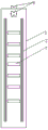
Fig. 1 is a schematic structural diagram of a hoistway hoisting frame structure according to the present invention;
FIG. 2 is a schematic structural view of the lifting frame of the present invention fixed between two slide guides;
fig. 3 is a schematic view of the structure of the side surface of the guide carriage.
Reference numerals: the device comprises a 1-guide sliding frame, a 2-guide sliding rail, a 3-lifting frame, a 3.1-base, a 3.2-protective frame, a 4-guide pulley, a 5-bidirectional telescopic cylinder, a 6-movable block, a 7-jack, an 8-pull rope, a 9-traction wheel, a 10-take-up and pay-off mechanism, a 10.1-frame, a 10.2-winding roller, a 10.3-driven wheel, a 10.4-driving wheel and a 10.5-stepping motor.
Detailed Description
In order to make the objects, technical solutions and advantages of the present invention more clearly understood, the present invention is further described in detail below with reference to the accompanying drawings and embodiments. It should be understood that the specific embodiments described herein are for purposes of illustration only and are not intended to limit the invention, i.e., the described embodiments are only some, but not all embodiments of the invention. The components of embodiments of the present invention, as generally described and illustrated in the figures herein, may be arranged and designed in a wide variety of different configurations.
Thus, the following detailed description of the embodiments of the present invention, presented in the accompanying drawings, is not intended to limit the scope of the invention, as claimed, but is merely representative of selected embodiments of the invention. Based on the embodiment of the present invention, all other embodiments obtained by the person skilled in the art without creative work belong to the protection scope of the present invention.
It is noted that relational terms such as "first" and "second," and the like, may be used solely to distinguish one entity or action from another entity or action without necessarily requiring or implying any actual such relationship or order between such entities or actions. Also, the terms "comprises," "comprising," or any other variation thereof, are intended to cover a non-exclusive inclusion, such that a process, method, article, or apparatus that comprises a list of elements does not include only those elements but may include other elements not expressly listed or inherent to such process, method, article, or apparatus. Without further limitation, an element defined by the phrase "comprising an … …" does not exclude the presence of other identical elements in a process, method, article, or apparatus that comprises the element.
The features and properties of the present invention are described in further detail below with reference to examples.
Example 1
As shown in fig. 1 to 3, this embodiment provides a well hoisting frame structure, including two vertical leading balladeur train 1 of arranging, two one sides that lead balladeur train 1 is relative all is provided with two vertical smooth tracks 2 of leading, two are led and are provided with hoisting frame 3 between the balladeur train 1, hoisting frame 3 is connected with the rope and draws high mechanism, 3 both sides of hoisting frame all are provided with and correspond and lead smooth track 2 complex pulley 4 of leading, be provided with the two-way telescoping cylinder 5 that the level was arranged in the hoisting frame 3, the piston rod at 5 both ends of two-way telescoping cylinder all is connected with movable block 6, lead and all seted up a plurality ofly and correspond movable block 6 complex jack 7 along its vertical direction on the balladeur train 1, jack 7 all is located two and leads between the smooth track 2.
In this embodiment, after hoisting the hoisting frame to the take the altitude through rope lifting mechanism, promote both sides movable block through the two-way telescoping cylinder in the hoisting frame and insert in corresponding the jack, the movable block is partly still in the base this moment, thereby make hoisting frame monolithic stationary guide between the carriage at two, operating personnel can carry out elevator well installation construction operation at this height with the hoisting frame as construction platform, regard as supporting component with the movable block this moment, greatly reduced draws the stress of lifting mechanism to the rope, long service life, can not cause the incident because of rope snap, construction safety has been guaranteed.
Example 2
As shown in fig. 1 to 2, the present embodiment is further optimized on the basis of embodiment 1, specifically, the lifting frame 3 includes a base 3.1, a protection frame 3.2 is provided on the base 3.1, an operator uses the base 3.1 as an operation platform, and the operator is in the protection frame 3.2, the safety is high, the bidirectional telescopic cylinder 5 is provided in the base 3.1, the movable block 6 can slide in the base 3.1, the movable block 6 is used as a temporary support component, the structure is firm and stable, the pulley 4 is provided at two side ends of the base 3.1, the top of the protection frame 3.2 is open, the protection frame 3.2 is formed by vertically and horizontally welding a plurality of angle steels or steel bars, the cost is low, and the manufacturing difficulty is low.
Example 3
As shown in fig. 1 to 2, the present embodiment is further optimized on the basis of embodiment 2, specifically, the rope lifting mechanism includes two pulling ropes 8 connected to the top of the base 3.1, the protection frame 3.2 is located between the two pulling ropes 8, the top of the guide carriage 1 is provided with a plurality of traction wheels 9 for pulling the pulling ropes 8, the other end of the pulling ropes 8 is connected to the take-up and pay-off mechanism 10 located outside the guide carriage 1, the take-up and pay-off mechanism 10 includes a frame 10.1, a winding roller 10.2 is rotatably provided on the frame 10.1, the pulling ropes 8 are wound on the winding roller 10.2, one end of the winding roller 10.2 is connected to the driven wheel 10.3 through a rotating shaft, the driven wheel 10.3 is connected to the driving wheel 10.4 through a driving belt, and the driving wheel 10.4 is connected to.
In this embodiment, rope pulling-up mechanism during operation starts step motor and drives the wire winding running roller and rotate and receive the line to the stay cord to make the base in the stay cord pulling hoisting frame shift up along leading smooth track, when moving to a certain height on, step motor stall utilizes its self-locking function, makes the hoisting frame stabilize in this position, and after the construction, step motor reversal carries out the unwrapping wire to the stay cord, can make the hoisting frame wholly move down, and convenient operation is swift, and degree of automation is high.
The above description is only for the preferred embodiment of the present invention, and the present invention is not limited thereto, the protection scope of the present invention is defined by the claims, and all structural changes equivalent to the contents of the description and drawings of the present invention should be included in the protection scope of the present invention.
Claims (5)
1. The utility model provides a well hoisting frame structure, a serial communication port, including two vertical guide sliding frame (1) of arranging, two one sides that guide sliding frame (1) is relative all are provided with two vertical and lead smooth track (2), two are led and are provided with hoisting frame (3) between sliding frame (1), hoisting frame (3) are connected with rope and draw high mechanism, hoisting frame (3) both sides end all is provided with and leads smooth track (2) complex guide pulley (4) with corresponding, be provided with two-way telescoping cylinder (5) that the level was arranged in hoisting frame (3), the piston rod at two-way telescoping cylinder (5) both ends all is connected with movable block (6), lead sliding frame (1) and go up all seted up a plurality ofly and correspond movable block (6) complex jack (7) along its vertical direction, jack (7) all are located two and lead between smooth track (2).
2. A hoistway lifting frame structure according to claim 1, wherein the lifting frame (3) comprises a base (3.1), a protective frame (3.2) is arranged on the base (3.1), a bidirectional telescopic cylinder (5) is arranged in the base (3.1), a movable block (6) can slide in the base (3.1), and guide pulleys (4) are arranged at two side ends of the base (3.1).
3. A hoistway lifting frame structure according to claim 2, wherein the top of the protective frame (3.2) is open, and the protective frame (3.2) is formed by welding a plurality of angle steels or steel bars in a longitudinal and transverse manner.
4. A hoistway lifting frame structure according to claim 2, wherein the rope lifting mechanism comprises two pulling ropes (8) connected to the top of the base (3.1), the protective frame (3.2) is arranged between the two pulling ropes (8), the top of the guide carriage (1) is provided with a plurality of traction wheels (9) for drawing the pulling ropes (8), and the other end of each pulling rope (8) is connected with a take-up and pay-off mechanism (10) arranged outside the guide carriage (1).
5. The hoistway lifting frame structure of claim 4, wherein the take-up and pay-off mechanism (10) comprises a frame (10.1), a winding roller (10.2) is rotatably arranged on the frame (10.1), the pull rope (8) is wound on the winding roller (10.2), one end of the winding roller (10.2) is connected with a driven wheel (10.3) through a rotating shaft, the driven wheel (10.3) is connected with a driving wheel (10.4) through a transmission belt, and the driving wheel (10.4) is connected with a stepping motor (10.5).
Priority Applications (1)
| Application Number | Priority Date | Filing Date | Title |
|---|---|---|---|
| CN201920944611.XU CN210176288U (en) | 2019-06-21 | 2019-06-21 | Well hoisting frame structure |
Applications Claiming Priority (1)
| Application Number | Priority Date | Filing Date | Title |
|---|---|---|---|
| CN201920944611.XU CN210176288U (en) | 2019-06-21 | 2019-06-21 | Well hoisting frame structure |
Publications (1)
| Publication Number | Publication Date |
|---|---|
| CN210176288U true CN210176288U (en) | 2020-03-24 |
Family
ID=69838440
Family Applications (1)
| Application Number | Title | Priority Date | Filing Date |
|---|---|---|---|
| CN201920944611.XU Expired - Fee Related CN210176288U (en) | 2019-06-21 | 2019-06-21 | Well hoisting frame structure |
Country Status (1)
| Country | Link |
|---|---|
| CN (1) | CN210176288U (en) |
-
2019
- 2019-06-21 CN CN201920944611.XU patent/CN210176288U/en not_active Expired - Fee Related
Similar Documents
| Publication | Publication Date | Title |
|---|---|---|
| CN109653481A (en) | A kind of hanging rail formula high-altitude operation platform and production method | |
| CN201033710Y (en) | Elevator capable of lifting and mounting automatically | |
| JP2003020175A (en) | Installation frame for installation of shaft device, installation lift therewith, and method of installing shaft device | |
| CN210176288U (en) | Well hoisting frame structure | |
| CN210915083U (en) | Efficient and energy-saving lifting equipment for mine exploitation | |
| CN214006474U (en) | Outer wall construction structure for building | |
| CN115385276A (en) | Novel lifting platform for outer wall of tower barrel of wind driven generator set | |
| CN114033151A (en) | Aerial work hanging basket system suitable for various wall surface conditions | |
| CN209740630U (en) | Intelligent detection system for hanging basket anti-falling device | |
| CN108868171B (en) | Pitching follow-up crossing frame and control method thereof | |
| JPH09278325A (en) | Construction work elevator lifting method and construction work elevator device | |
| CN212075917U (en) | Cable winding displacement device for building elevator | |
| CN218491399U (en) | Climbing type elevator installation device | |
| CN219885608U (en) | Hoisting platform in elevator well | |
| CN111320113B (en) | Debugging table and debugging method | |
| CN212101899U (en) | Debugging table | |
| CN214733677U (en) | Elevator car traction mechanism | |
| CN218879393U (en) | Comprehensive operation platform for oil well workover | |
| CN214995832U (en) | Rail crane ship capable of horizontally and vertically walking for high-altitude suspension construction of building | |
| CN217478905U (en) | Bridge crane convenient to overhaul | |
| CN215167876U (en) | Climbing frame system and chain reversing device thereof | |
| CN214003102U (en) | Automatic abrupt slope material conveying device for highway maintenance | |
| CN219411735U (en) | Safety lifting scaffold for constructional engineering | |
| CN218345028U (en) | Vertical transportation equipment for small materials | |
| CN219950303U (en) | Prefabricated component hangs and gets device |
Legal Events
| Date | Code | Title | Description |
|---|---|---|---|
| GR01 | Patent grant | ||
| GR01 | Patent grant | ||
| CF01 | Termination of patent right due to non-payment of annual fee | ||
| CF01 | Termination of patent right due to non-payment of annual fee |
Granted publication date: 20200324 Termination date: 20210621 |