CN210147679U - Device convenient to timber is polished - Google Patents
Device convenient to timber is polished Download PDFInfo
- Publication number
- CN210147679U CN210147679U CN201920682959.6U CN201920682959U CN210147679U CN 210147679 U CN210147679 U CN 210147679U CN 201920682959 U CN201920682959 U CN 201920682959U CN 210147679 U CN210147679 U CN 210147679U
- Authority
- CN
- China
- Prior art keywords
- motor
- screw rod
- fixedly connected
- lead screw
- timber
- Prior art date
- Legal status (The legal status is an assumption and is not a legal conclusion. Google has not performed a legal analysis and makes no representation as to the accuracy of the status listed.)
- Active
Links
Images


Abstract
The utility model discloses a device convenient to timber is polished, including the bottom plate, the upper end of bottom plate is equipped with the backup pad, the upper end fixedly connected with lead screw support of backup pad, and lead screw support's inside fixed mounting has the bearing, and lead screw support's inside is equipped with the lead screw, and lead screw support's lower extreme is equipped with the slider, the lower extreme fixedly connected with motor frame of slider, the first motor of motor frame fixedly connected with and second motor, the internally mounted of first motor has the motor shaft, and the one end fixed mounting of motor shaft has the abrasive disc. First motor and second motor drive the abrasive disc simultaneous working, and two faces of timber are polished simultaneously, because rotate the crank and make the lead screw drive the slider side-to-side movement and adjust the distance between two abrasive discs and make it can polish the timber of different width, the T-shaped piece can be in T shape downthehole up-and-down motion of hole has an effect to timber downwards, makes timber need not the workman to press from both sides tightly when polishing and alleviates workman's intensity of labour.
Description
Technical Field
The utility model relates to a timber technical field that polishes specifically is a device convenient to timber is polished.
Background
Wood plays a great supporting role in human life. According to different property characteristics of wood, people use the wood in different ways, such as processing the wood into furniture, office appliances and the like, the wood needs to be polished in the processing process, the surface of square wood is fine and beautiful after being polished, however, the wood is usually polished manually;
1. the existing square timber polishing device can only polish one surface of the square timber each time, so that the working efficiency is reduced;
2. the existing square timber polishing device needs workers to clamp square timber to increase the labor intensity of the workers when square timber is polished at each time.
SUMMERY OF THE UTILITY MODEL
An object of the utility model is to provide a device convenient to timber is polished to solve current square timber grinding device and polish at every turn and can only polish a face of square timber, need workman's square timber to press from both sides tight problem when polishing square timber at every turn.
In order to achieve the above object, the utility model provides a following technical scheme: a device convenient for wood polishing is characterized in that a supporting plate is arranged at the upper end of a bottom plate, a lead screw support is fixedly connected to the upper end of the supporting plate, a supporting block is fixedly connected to the upper end of the bottom plate, a positioning screw hole is formed in the supporting block, a wood block support is fixedly connected to the upper end of the supporting block, a bearing is fixedly installed inside the lead screw support, a lead screw is arranged inside the lead screw support, bearings are fixedly installed at two ends of the lead screw, a lead screw shaft is arranged at one end of the lead screw, first threads are arranged on the surface of the lead screw, a crank is fixedly connected to the lead screw shaft, a sliding block is arranged at the lower end of the lead screw support, second threads are arranged inside the sliding block, a connecting block is fixedly connected to the lower end of the sliding block, a motor frame is arranged at the lower end of the connecting, and one end of the motor shaft is fixedly provided with a grinding disc.
Preferably, the first motor and the second motor are symmetrically distributed about a vertical center line of the screw rod bracket.
Preferably, the lower surface of the screw rod support is parallel to the upper surface of the bottom plate.
Preferably, the middle of the upper end of the wood block support is provided with a positioning block, a T-shaped hole is formed in the positioning block, a reset spring is arranged in the T-shaped hole, one end of the reset spring is provided with a T-shaped block, the lower end of the T-shaped block is fixedly connected with an I-shaped frame, a roller is fixedly arranged in the I-shaped frame, and a roller is sleeved on the roller in a sliding mode.
Preferably, roller stoppers are fixedly mounted at both ends of the roller.
Compared with the prior art, the beneficial effects of the utility model are that:
1. the grinding discs are driven by the first motor and the second motor to work simultaneously, two surfaces of the square timber can be ground simultaneously, and the crank is rotated to enable the screw rod to drive the sliding block to move left and right to adjust the distance between the two grinding discs, so that the square timber with different widths can be ground;
2. through inserting square timber in the billet support, the T-shaped piece can move up and down in T shape downthehole to the effect that has an effect of side timber downwards, makes square timber not need the workman to press from both sides tightly when polishing and alleviates workman's intensity of labour.
Drawings
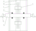
Fig. 1 is a schematic view of the overall structure of the present invention;
fig. 2 is a top view of the present invention;
fig. 3 is an enlarged view of the positioning block structure of part a of the present invention.
In the figure: the device comprises a crank 1, a screw shaft 2, a bearing 3, a screw rod bracket 4, a first thread 5, a sliding block 6, a second thread 7, a screw rod 8, a supporting plate 9, a connecting block 10, a motor bracket 11, a grinding sheet 12, a first motor 13, a motor shaft 14, a supporting block 15, a second motor 16, a wood block bracket 17, a bottom plate 18, a positioning screw hole 19, a positioning block 20, a T-shaped block 21, a T-shaped hole 22, a return spring 23, a roller 24, an I-shaped bracket 25, a roller 26 and a roller block 27.
Detailed Description
The technical solutions in the embodiments of the present invention will be described clearly and completely with reference to the accompanying drawings in the embodiments of the present invention, and it is obvious that the described embodiments are only some embodiments of the present invention, not all embodiments. Based on the embodiments in the present invention, all other embodiments obtained by a person skilled in the art without creative work belong to the protection scope of the present invention.
Referring to fig. 1 and fig. 2, the present invention provides a technical solution: a device convenient for wood polishing comprises a bottom plate 18, wherein the bottom plate 18 is made of cast iron HT200 and has the characteristic of difficult deformation, a supporting plate 9 is fixedly connected to the upper end of the bottom plate 18 through bolts, two supporting plates 9 are fixed in a rectangular shape and are bilaterally symmetrical to each other about the bottom plate 18, a screw rod support 4 is fixedly connected to the upper end of the supporting plate 9 through bolts, the screw rod support 4 is made of 45# steel and is convenient to machine and form, a supporting block 15 is fixedly connected to the upper end of the bottom plate 18 through bolts, the supporting block 15 is made of aluminum alloy and is light in weight, equidistant positioning screw holes 19 are processed in the supporting block 15, the positioning screw holes 19 are used for adjusting the distance between the two wood block supports 17 according to the lengths of different square timbers, the wood block supports 17 are fixedly connected to the upper end of the supporting block 15 through bolts, the square timbers are placed into the, the bearing 3 is fixedly arranged in the lead screw bracket 4, the bearing 3 is a ball bearing, the lead screw 8 is arranged in the lead screw bracket 4 through the bearing 3, the bearing 3 is fixedly arranged at two ends of the lead screw 8, the bearing 3 is used for fixing the lead screw 8 and facilitating the rotation of the lead screw, a lead screw shaft 2 is machined at one end of the lead screw 8 through a lathe, a first thread 5 is machined on the surface of the lead screw 8 through the lathe, the lead screw shaft 2 is fixedly connected with a crank 1 through welding, the crank 1 is used for facilitating the rotation of the lead screw 8, a sliding block 6 is arranged at the lower end of the lead screw bracket 4, the sliding block 6 is made of No. 45 steel, a second thread 7 is machined in the sliding block 6, the second thread 7 is meshed with the first thread 5, a connecting block 10 is fixedly connected at the lower end of the sliding block 6, a motor bracket 11 is fixedly connected at the lower end of the, the model of the first motor 13 and the second motor 16 is 5M120GN-RV40-2, the switch is provided with a switch, the switch has the functions of forward transmission, stopping and reverse rotation, the switch is connected to an external 220V power supply through a lead, a motor shaft 14 is installed inside the first motor 13, one end of the motor shaft 14 is provided with a thread, one end of the motor shaft 14 provided with the thread is fixedly provided with a grinding sheet 12 through a nut, and the size of the grinding sheet 12 is phi 250 x 25 x 32 mm.
Referring to fig. 1, the first motor 13 and the second motor 16 are symmetrically distributed about a vertical center line of the screw bracket 4.
Referring to fig. 1, the lower surface of the lead screw bracket 4 and the upper surface of the bottom plate 18 are parallel to each other.
Referring to fig. 3, a positioning block 20 is fixedly mounted in the middle of the upper end of a wood block support 17, the positioning block 20 is made of 45# steel, a T-shaped hole 22 is formed in the positioning block 20, and the surface smoothness ra3.2 in the T-shaped hole 22 is beneficial to the sliding of the T-shaped block 21 in the positioning block, a return spring 23 is slidably mounted in the T-shaped hole 22, the return spring 23 deforms under the action of external force, and after the external force is removed, the spring can recover to the original shape, one end of the return spring 23 is provided with the T-shaped block 21, the T-shaped block 21 is made of hard alloy and is not easy to wear and abrade, the surface polishing treatment is performed, the lower end of the T-shaped block 21 is fixedly connected with a i-shaped frame 25 in a welding manner, a roller 26 is fixedly mounted in the i-shaped frame 25, the roller 26 is made of 45# steel and, preventing the surface of the square timber from being scratched.
Referring to fig. 3, roller stoppers 27 are fixedly mounted at both ends of the roller 24, and the roller stoppers 27 prevent the left and right ends of the roller 24 from sliding.
The utility model discloses when concrete implementation: when the surface of square timber needs to be polished, the square timber is the timber of which the cross section is square, the square timber is inserted into two wood block supports 17 which are symmetrically installed about a screw rod support 4, a roller 24 is fixed at the lower end of a T-shaped block 21 through an I-shaped frame 25, the T-shaped block 21 can move up and down in a T-shaped hole 22 according to the thickness of the square timber to enable the roller 24 to have an effect on downward force on the square timber, the square timber does not need to be clamped by a worker to reduce the labor intensity of the worker when being polished, a first motor 13 is started to enable the square timber to rotate anticlockwise and a second motor 16 to rotate clockwise to drive grinding plates 12 to work simultaneously, two surfaces of the square timber can be polished simultaneously, and a crank 1 is rotated according to the different widths of the square timber to enable a screw rod 8 to drive a sliding block 6 to move left.
Although embodiments of the present invention have been shown and described, it will be appreciated by those skilled in the art that changes, modifications, substitutions and alterations can be made in these embodiments without departing from the principles and spirit of the invention, the scope of which is defined in the appended claims and their equivalents.
Claims (5)
1. A device for facilitating the sanding of wood, comprising a base plate (18), characterized in that: the upper end of the bottom plate (18) is provided with a supporting plate (9), the upper end of the supporting plate (9) is fixedly connected with a screw rod support (4), the upper end of the bottom plate (18) is fixedly connected with a supporting block (15), the supporting block (15) is provided with a positioning screw hole (19), the upper end of the supporting block (15) is fixedly connected with a wood block support (17), a bearing (3) is fixedly arranged inside the screw rod support (4), a screw rod (8) is arranged inside the screw rod support (4), the bearings (3) are fixedly arranged at two ends of the screw rod (8), one end of the screw rod (8) is provided with a screw rod shaft (2), a first thread (5) is arranged on the surface of the screw rod (8), the screw rod shaft (2) is fixedly connected with a crank (1), the lower end of the screw rod support (4) is provided with a sliding block (6), and a second, the lower extreme fixedly connected with connecting block (10) of slider (6), the lower extreme of connecting block (10) is equipped with motor frame (11), first motor (13) of motor frame (11) fixedly connected with and second motor (16), the internally mounted of first motor (13) has motor shaft (14), the one end fixed mounting of motor shaft (14) has abrasive disc (12).
2. A device for facilitating the sanding of wood according to claim 1, wherein: the first motor (13) and the second motor (16) are symmetrically distributed about a vertical central line of the screw rod support (4).
3. A device for facilitating the sanding of wood according to claim 1, wherein: the lower surface of the screw rod support (4) is parallel to the upper surface of the bottom plate (18).
4. A device for facilitating the sanding of wood according to claim 1, wherein: be equipped with locating piece (20) in the middle of the upper end of billet support (17), the inside of locating piece (20) is equipped with T shape hole (22), the inside in T shape hole (22) is provided with reset spring (23), the one end of reset spring (23) is equipped with T shape piece (21), the lower extreme fixedly connected with worker shape frame (25) of T shape piece (21), the inside fixed mounting of worker shape frame (25) has roller (26), roller (26) slip cover has cylinder (24).
5. An apparatus for facilitating the sanding of wood according to claim 4, wherein: and roller stoppers (27) are fixedly arranged at two ends of the roller (24).
Priority Applications (1)
| Application Number | Priority Date | Filing Date | Title |
|---|---|---|---|
| CN201920682959.6U CN210147679U (en) | 2019-05-14 | 2019-05-14 | Device convenient to timber is polished |
Applications Claiming Priority (1)
| Application Number | Priority Date | Filing Date | Title |
|---|---|---|---|
| CN201920682959.6U CN210147679U (en) | 2019-05-14 | 2019-05-14 | Device convenient to timber is polished |
Publications (1)
| Publication Number | Publication Date |
|---|---|
| CN210147679U true CN210147679U (en) | 2020-03-17 |
Family
ID=69758961
Family Applications (1)
| Application Number | Title | Priority Date | Filing Date |
|---|---|---|---|
| CN201920682959.6U Active CN210147679U (en) | 2019-05-14 | 2019-05-14 | Device convenient to timber is polished |
Country Status (1)
| Country | Link |
|---|---|
| CN (1) | CN210147679U (en) |
Cited By (1)
| Publication number | Priority date | Publication date | Assignee | Title |
|---|---|---|---|---|
| CN113290645A (en) * | 2021-06-18 | 2021-08-24 | 石强 | Energy-saving building material processingequipment |
-
2019
- 2019-05-14 CN CN201920682959.6U patent/CN210147679U/en active Active
Cited By (2)
| Publication number | Priority date | Publication date | Assignee | Title |
|---|---|---|---|---|
| CN113290645A (en) * | 2021-06-18 | 2021-08-24 | 石强 | Energy-saving building material processingequipment |
| CN113290645B (en) * | 2021-06-18 | 2022-06-21 | 石强 | Energy-saving building material processingequipment |
Similar Documents
| Publication | Publication Date | Title |
|---|---|---|
| CN209394403U (en) | A kind of steel for machine building material grinding device | |
| CN212887016U (en) | Part is polished and is used anchor clamps | |
| CN205254720U (en) | A straight flange edging machine for sheet glass processes production | |
| CN210147679U (en) | Device convenient to timber is polished | |
| CN210024719U (en) | Rotating shaft polishing device for machining | |
| CN213225410U (en) | Metal material grinding device | |
| CN214351377U (en) | Frame polishing device for aluminum profile door and window | |
| CN211136538U (en) | Grinding device is used in precision bearing processing | |
| CN217966544U (en) | Burnishing machine is used in aluminium alloy processing | |
| CN209936575U (en) | Grinding device is used in bearing processing of convenient regulation | |
| CN216967382U (en) | Turnover saw blade polishing machine | |
| CN111015473A (en) | Decoating device is used in copper processing convenient to not unidimensional use | |
| CN216399024U (en) | Chamfering device for machining guide rail pressing plate | |
| CN214054639U (en) | Plate aluminum profile machining and polishing device | |
| CN210499698U (en) | Stainless steel product welding equipment of polishing | |
| CN212071370U (en) | Tubular material grinding device | |
| CN211053348U (en) | Aluminum alloy template multiaspect synchronous grinding device | |
| CN212471088U (en) | Substrate surface positioning and polishing device | |
| CN219170429U (en) | Polishing device for metal materials | |
| CN219966168U (en) | Punching device for production and processing of switch cabinet shell | |
| CN218427320U (en) | Metal working polishing mechanism | |
| CN218776386U (en) | Clamp for grinding machine | |
| CN217775283U (en) | Polishing and punching device for sheet metal machining | |
| CN220197284U (en) | Polishing device for aluminum plate surface machining | |
| CN218052012U (en) | Metal surface treatment burnishing device |
Legal Events
| Date | Code | Title | Description |
|---|---|---|---|
| GR01 | Patent grant | ||
| GR01 | Patent grant |